EP0056521B1 - Moteur électrique - Google Patents
Moteur électrique Download PDFInfo
- Publication number
- EP0056521B1 EP0056521B1 EP81305870A EP81305870A EP0056521B1 EP 0056521 B1 EP0056521 B1 EP 0056521B1 EP 81305870 A EP81305870 A EP 81305870A EP 81305870 A EP81305870 A EP 81305870A EP 0056521 B1 EP0056521 B1 EP 0056521B1
- Authority
- EP
- European Patent Office
- Prior art keywords
- rotor
- motor
- stator
- face
- flange
- Prior art date
- Legal status (The legal status is an assumption and is not a legal conclusion. Google has not performed a legal analysis and makes no representation as to the accuracy of the status listed.)
- Expired
Links
Images


Classifications
-
- H—ELECTRICITY
- H02—GENERATION; CONVERSION OR DISTRIBUTION OF ELECTRIC POWER
- H02K—DYNAMO-ELECTRIC MACHINES
- H02K21/00—Synchronous motors having permanent magnets; Synchronous generators having permanent magnets
- H02K21/38—Synchronous motors having permanent magnets; Synchronous generators having permanent magnets with rotating flux distributors, and armatures and magnets both stationary
Definitions
- the present invention relates to electric motors and more particularly to electric motors of the types disclosed in Specification No. GB-A-1600380.
- Such motors comprise a rotor of unmagnetised magnetic material having a radial face with a plurality of segments which are angularly distributed around the axis of rotation of the rotor, a stator including a plurality of permanent magnet poles having polefaces spaced apart and distributed around the axis of rotation of the rotor, all of which polefaces are spaced from and face said radial face of the rotor and present the same magnetic polarity thereto, and a winding wound upon the stator and so arranged that on energisation of the winding by an alternating current the relative flux density of adjacent ones of the polefaces is caused to alternate without polarity change about the mean value so that a segment is attracted towards the adjacent poleface of greater flux density and thereby to induce rotation of the rotor, the stator further including spaced inner and outer annular members which surround and
- the preambles of claims 1 and 11 correspond to motors as disclosed in GB-A-1600380.
- Figs. 4 and 5 of GB-A-1263386 disclose a motor with a stator having inner and outer annular members with teeth which are parallel to the magnetic field which is wholly radial.
- the rotor is magnetised and the stator members are adjacent to different faces of the rotor.
- a self-starting synchronous electric motor comprising a rotor of unmagnetised magnetic material having a radially extending face, and a stator comprising spaced inner and outer annular members which face the radially extending face of the rotor and which are concentric with and extend axially of the axis of rotation of the rotor, the stator having a plurality of permanent magnet pole elements which face the radially extending face of the rotor characterised in that the end of one or each of the annular members adjacent the rotor is provided with a radial flange which extends towards the other annular member.
- the pole elements of the stator may all be of the same polarity.
- the inner and outer annular members may be provided with respective pluralities of pole elements or they may share a plurality of pole elements.
- the latter option has the advantage of simplifying assembly of the motor. Further simplification may be achieved by employing a single magnetised disc to provide said pole elements.
- the or each flange may be of the same material as the annular members, in which case it is preferably integral with the respective annular member, thus saving an assembly step.
- an integral flange means that during assembly a coil for the stator has to be wound around the inner annular member. If a separate flange is used, either of the same or different material, there is the advantage that an already wound coil may be placed on to the inner annular member of the stator.
- an alternating current synchronous electric motor comprising a rotor of unmagnetised magnetic material having a radial face with a plurality of segments which are angularly distributed around the axis of rotation of the rotor, a stator including a plurality of permanent magnet poles having polefaces spaced apart and distributed around the axis of rotation of the rotor, all of which polefaces are spaced from and face said radial face of the rotor and present the same magnetic polarity thereto, and a winding wound upon the stator and so arranged that on energisation of the winding by an alternating current the relative flux density of adjacent ones of the polefaces is caused to alternate without polarity change about the mean value so that a segment is attracted towards the adjacent poleface of greater flux density thereby to induce rotation of the rotor, the stator further including spaced inner and outer annular members which surround and extend axially of the axis of rotation of the rotor and upon
- Fig. 1 shows an electric motor comprising a magnetic rotor 7 and a stator assembly 1.
- the stator assembly comprises a core of magnetic material having an annular outer core element 2 and an annular inner core element 3 concentric with the outer core element. Elements 2, 3 define an annular space which is closed at the end remote from rotor 7 by annular portion 4.
- the stator assembly 1 further comprises permanent magnet stator pole elements 5A, 5B arranged at equal angular intervals about the axis of the core, alternate pole elements 5A, 5B around the core axis being carried by the outer and inner core elements 2, 3 respectively.
- the pole elements 5A, 5B have flat coplanar polefaces 6 which lie in a plane perpendicular to the axis of stator assembly 1.
- Inner core element 3 of the stator assembly is of hollow tubular construction and houses a nonmagnetic bearing assembly 10 for a rotor shaft 11.
- a motor winding 12 is wound concentrically in the annular space between the core element, 2, 3.
- the motor is the same as that disclosed in Specification No. GB-A-1600380 the contents of which are hereby incorporated into the present specification.
- the improvement of the present embodiment lies in the provision of a flange portion 31 on the outer core element 2.
- Flange 31 extends radially inwardly towards inner core element 3 to define a gap 30.
- the flux of the permanent magnet pole elements, 5A, 5B is substantially unaffected by flange 31 and has an air return path as in the above mentioned copending application.
- Figure 2 shows a second embodiment of the present invention.
- a flange portion 32 is provided which extends radially outwardly from the inner core element and parallel to the rotor. r.
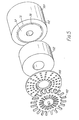
- Figure 3 shows a third embodiment of the present invention comprising a stator assembly 101 and a rotor 107.
- the motor may be a 10 mm motor with a 20 pole staggered rotor 107 weighing 0.24 gm.
- Stator assembly 101 comprises core elements 102, 103, 104 and permanent magnetic pole elements 105. Since all the elements 105 are of the same polarity they may be interconnected in groups as shown in Fig. 4, rather than separate as in the preceding embodiments. Furthermore, as shown in the modification of Fig. 5, all the pole segments may be provided on a single disc, the poles being magnetised in a desired pattern.
- flange portions 31, 32 are provided on both the outer and inner core elements 102, 103 to define a narrow air gap 30.
- a motor winding 112 is providing in the space defined by core elements 102, 103, 104 and flanges 31, 32.
- the winding comprises 6000 turns of 0.0305 mm diameter copper wire.
- An advantage of the above described arrangements is a substantially reduced power requirement for self-starting and running of the motors. Practical tests have shown that for the same motor, the requirement for self-starting and running was reduced from 1.52 mVA to 0.17 mVA by the provisions of flange portions.
- the core elements 102, 103, 104 may be made of free cutting steel (e.g. Ledbury) and flanges 31 and/or 32 may be made integral parts of the stator.
- the stator assembly then resembles a bobbin and the coil winding 112 is then wound upon it.
- the core elements may be made of moulded ferrite material. In this case rings of Mumetal (Registered Trade Mark) or radiometal may be inserted to provide the flange portions.
- the invention is not restricted to motors of the above type and flanges such as 31 and/or 32 may be provided in any stator having inner and outer concentric members.
Landscapes
- Engineering & Computer Science (AREA)
- Power Engineering (AREA)
- Valve Device For Special Equipments (AREA)
- Transition And Organic Metals Composition Catalysts For Addition Polymerization (AREA)
- Glass Compositions (AREA)
- Iron Core Of Rotating Electric Machines (AREA)
- Permanent Magnet Type Synchronous Machine (AREA)
- Synchronous Machinery (AREA)
- Permanent Field Magnets Of Synchronous Machinery (AREA)
Claims (11)
Priority Applications (1)
| Application Number | Priority Date | Filing Date | Title |
|---|---|---|---|
| AT81305870T ATE16664T1 (de) | 1981-01-15 | 1981-12-14 | Elektrischer motor. |
Applications Claiming Priority (2)
| Application Number | Priority Date | Filing Date | Title |
|---|---|---|---|
| GB8101232 | 1981-01-15 | ||
| GB8101232A GB2093277B (en) | 1981-01-15 | 1981-01-15 | Electric motor |
Publications (3)
| Publication Number | Publication Date |
|---|---|
| EP0056521A2 EP0056521A2 (fr) | 1982-07-28 |
| EP0056521A3 EP0056521A3 (en) | 1983-01-26 |
| EP0056521B1 true EP0056521B1 (fr) | 1985-11-21 |
Family
ID=10518999
Family Applications (1)
| Application Number | Title | Priority Date | Filing Date |
|---|---|---|---|
| EP81305870A Expired EP0056521B1 (fr) | 1981-01-15 | 1981-12-14 | Moteur électrique |
Country Status (5)
| Country | Link |
|---|---|
| EP (1) | EP0056521B1 (fr) |
| JP (1) | JPS57135663A (fr) |
| AT (1) | ATE16664T1 (fr) |
| DE (1) | DE3173027D1 (fr) |
| GB (1) | GB2093277B (fr) |
Families Citing this family (4)
| Publication number | Priority date | Publication date | Assignee | Title |
|---|---|---|---|---|
| GB8419400D0 (en) * | 1984-07-30 | 1984-09-05 | Horstmann Gear Group Ltd | Electric motors |
| SE530697C2 (sv) | 2006-12-19 | 2008-08-19 | Bae Systems Haegglunds Ab | Rotor till en elmotor, rotorplåtar för uppbyggnad av rotorn, samt en elmotor med en sådan rotor |
| USD1000124S1 (en) | 2020-03-17 | 2023-10-03 | Braun Gmbh | Battery-operated toothbrush |
| USD972303S1 (en) * | 2020-09-17 | 2022-12-13 | Braun Gmbh | Battery operated toothbrush |
Family Cites Families (5)
| Publication number | Priority date | Publication date | Assignee | Title |
|---|---|---|---|---|
| GB845394A (en) * | 1957-10-23 | 1960-08-24 | Landis & Gyr Ag | Improvements in or relating to self-starting fractional horse-power synchronous motors |
| FR1574848A (fr) * | 1968-05-10 | 1969-07-18 | ||
| CH567876A4 (en) * | 1976-05-06 | 1977-08-31 | Dust filter esp for textile waste - is intermittently blown back with large deformation of filter cloth | |
| GB1600380A (en) * | 1977-06-30 | 1981-10-14 | Horstmann Clifford Magnetics C | Electric motors |
| DE2828842A1 (de) * | 1978-06-30 | 1980-01-17 | Paul Merkle | Langsamlaufender wechselstrom-synchronmotor |
-
1981
- 1981-01-15 GB GB8101232A patent/GB2093277B/en not_active Expired
- 1981-12-14 AT AT81305870T patent/ATE16664T1/de not_active IP Right Cessation
- 1981-12-14 EP EP81305870A patent/EP0056521B1/fr not_active Expired
- 1981-12-14 DE DE8181305870T patent/DE3173027D1/de not_active Expired
- 1981-12-28 JP JP56215962A patent/JPS57135663A/ja active Pending
Also Published As
| Publication number | Publication date |
|---|---|
| EP0056521A3 (en) | 1983-01-26 |
| GB2093277B (en) | 1985-02-20 |
| GB2093277A (en) | 1982-08-25 |
| EP0056521A2 (fr) | 1982-07-28 |
| ATE16664T1 (de) | 1985-12-15 |
| DE3173027D1 (en) | 1986-01-02 |
| JPS57135663A (en) | 1982-08-21 |
Similar Documents
| Publication | Publication Date | Title |
|---|---|---|
| US4322648A (en) | Permanent magnet motor armature | |
| US5378953A (en) | Rotor for synchronous motor | |
| US4009406A (en) | Synchronous micromotor with a permanent magnet rotor | |
| EP1734645B1 (fr) | Moteur électrique du type à entrefer axial | |
| US4559463A (en) | Large surface area permanent magnet type rotary electrical machine | |
| US4788465A (en) | Armature for DC motor | |
| US3153157A (en) | Electromotor | |
| US4591766A (en) | Brushless direct current motor | |
| KR100432954B1 (ko) | 레이디얼 코어타입 더블 로터 방식의 비엘디씨 모터 | |
| US3495111A (en) | Small permanent magnet rotor shaded pole motor | |
| US4600910A (en) | Limited angle torque motor with high torque output multiple coils and increased magnetic centering torque | |
| US4820951A (en) | Multiphase small size brushless DC motor | |
| EP0056521B1 (fr) | Moteur électrique | |
| US4246504A (en) | Electric motors | |
| EP0187038A3 (fr) | Moteur-couple à pôles de grand couple et centrage magnétique par ajustement d'un ressort | |
| US3414751A (en) | Synchronous electrical motor | |
| US3848146A (en) | Ac motor | |
| JP2945441B2 (ja) | 永久磁石を用いたモータ | |
| JPH0150182B2 (fr) | ||
| US4757225A (en) | Dual stack tachometer/generator | |
| GB1600380A (en) | Electric motors | |
| JPH0150183B2 (fr) | ||
| JPH06178468A (ja) | モータ用固定子 | |
| JPH0822135B2 (ja) | モ−タのロ−タマグネツト | |
| JPS5837789B2 (ja) | ブラシレスモ−タ− |
Legal Events
| Date | Code | Title | Description |
|---|---|---|---|
| PUAI | Public reference made under article 153(3) epc to a published international application that has entered the european phase |
Free format text: ORIGINAL CODE: 0009012 |
|
| AK | Designated contracting states |
Designated state(s): AT BE CH DE FR IT LI LU NL SE |
|
| PUAL | Search report despatched |
Free format text: ORIGINAL CODE: 0009013 |
|
| AK | Designated contracting states |
Designated state(s): AT BE CH DE FR IT LI LU NL SE |
|
| 17P | Request for examination filed |
Effective date: 19830606 |
|
| ITF | It: translation for a ep patent filed |
Owner name: DR. ING. A. RACHELI & C. |
|
| GRAA | (expected) grant |
Free format text: ORIGINAL CODE: 0009210 |
|
| AK | Designated contracting states |
Designated state(s): AT BE CH DE FR IT LI LU NL SE |
|
| PG25 | Lapsed in a contracting state [announced via postgrant information from national office to epo] |
Ref country code: NL Effective date: 19851121 Ref country code: BE Effective date: 19851121 Ref country code: AT Effective date: 19851121 |
|
| REF | Corresponds to: |
Ref document number: 16664 Country of ref document: AT Date of ref document: 19851215 Kind code of ref document: T |
|
| PG25 | Lapsed in a contracting state [announced via postgrant information from national office to epo] |
Ref country code: SE Effective date: 19851130 |
|
| PG25 | Lapsed in a contracting state [announced via postgrant information from national office to epo] |
Ref country code: LU Free format text: LAPSE BECAUSE OF NON-PAYMENT OF DUE FEES Effective date: 19851231 |
|
| REF | Corresponds to: |
Ref document number: 3173027 Country of ref document: DE Date of ref document: 19860102 |
|
| ET | Fr: translation filed | ||
| NLV1 | Nl: lapsed or annulled due to failure to fulfill the requirements of art. 29p and 29m of the patents act | ||
| PLBE | No opposition filed within time limit |
Free format text: ORIGINAL CODE: 0009261 |
|
| STAA | Information on the status of an ep patent application or granted ep patent |
Free format text: STATUS: NO OPPOSITION FILED WITHIN TIME LIMIT |
|
| 26N | No opposition filed | ||
| PG25 | Lapsed in a contracting state [announced via postgrant information from national office to epo] |
Ref country code: LI Effective date: 19881231 Ref country code: CH Effective date: 19881231 |
|
| PG25 | Lapsed in a contracting state [announced via postgrant information from national office to epo] |
Ref country code: FR Free format text: LAPSE BECAUSE OF NON-PAYMENT OF DUE FEES Effective date: 19890831 |
|
| REG | Reference to a national code |
Ref country code: CH Ref legal event code: PL |
|
| PG25 | Lapsed in a contracting state [announced via postgrant information from national office to epo] |
Ref country code: DE Effective date: 19890901 |
|
| REG | Reference to a national code |
Ref country code: FR Ref legal event code: ST |