EP0056480A2 - Use of nickel base alloy having high resistance to stress corrosion cracking - Google Patents
Use of nickel base alloy having high resistance to stress corrosion cracking Download PDFInfo
- Publication number
- EP0056480A2 EP0056480A2 EP81110688A EP81110688A EP0056480A2 EP 0056480 A2 EP0056480 A2 EP 0056480A2 EP 81110688 A EP81110688 A EP 81110688A EP 81110688 A EP81110688 A EP 81110688A EP 0056480 A2 EP0056480 A2 EP 0056480A2
- Authority
- EP
- European Patent Office
- Prior art keywords
- corrosion cracking
- base alloy
- high resistance
- stress corrosion
- member made
- Prior art date
- Legal status (The legal status is an assumption and is not a legal conclusion. Google has not performed a legal analysis and makes no representation as to the accuracy of the status listed.)
- Granted
Links
Images

Classifications
-
- C—CHEMISTRY; METALLURGY
- C22—METALLURGY; FERROUS OR NON-FERROUS ALLOYS; TREATMENT OF ALLOYS OR NON-FERROUS METALS
- C22C—ALLOYS
- C22C19/00—Alloys based on nickel or cobalt
- C22C19/03—Alloys based on nickel or cobalt based on nickel
- C22C19/05—Alloys based on nickel or cobalt based on nickel with chromium
- C22C19/051—Alloys based on nickel or cobalt based on nickel with chromium and Mo or W
- C22C19/055—Alloys based on nickel or cobalt based on nickel with chromium and Mo or W with the maximum Cr content being at least 20% but less than 30%
Definitions
- the present invention relates to a member made of an Ni base alloy having a high resistance to stress corrosion cracking, suitable for use under an atmosphere of a temperature below creep temperature, particularly in contact with water of high temperature in various plants treating high temperature water such as boiling water reactors or pressurized water reactors. More particularly, the invention relates to various parts made of the Ni base alloy such as retainer beam of jet pump for nuclear reactors, springs and bolts used in the nuclear reactors and so forth. The invention is concerned also with a method of producing such parts.
- X750 alloy An alloy generally called inconel X750 (referred to as X750 alloy, hereinafter), i.e. Aerospace Material Specification (AMS) 5667H, which is an Ni base alloy of the precipitation strengthening type having a high modulus of elasticity and a large high-temperature strength, finds a spreading use as the material of various parts in nuclear reactors, such as retainer beam of jet pump, springs, bolts and so forth.
- AMS Aerospace Material Specification
- This X750 alloy has a Cr content of around 15% and is usually regarded as being a corrosion resistant material.
- the X750 alloy often occurs stress corrosion cracking when used in contact with water of a high temperature such as the water circulated through nuclear reactors, depending on the nature or quality of the water. More specifically, the X750 alloy tends to exhibit an intergranular stress corrosion cracking when it is subjected to a pure water of a high temperature of about 290°C under a condition subjected to tensile stress, particularly when there is a crevice in the surface onto which the tensile stress acts.
- USSN 1967-653665 and USSN 1965-459110 disclose Ni-base alloys having a high resistance to stress corrosion cracking suitable for use in contact with highly pure water of high pressure and temperature, as in the case of pressure vessel type heat exchangers, steam generator and so forth. More specifically, the specification of USSN 1967-653665 discloses an alloy consisting essentially of 14 to 35% of Cr, 0 to 25% of Fe, less than 0.5% of one or both of Ti and Al, 0 to 15% of C, 0 to 1% of Si, 0 to 7.7% of Mo, 0 to 1.2% of Ta and the balance Ni, wherein the Cr content is less than 20% when the alloy has a substantial Mo or Ta content.
- USSN 1965-459110 discloses an improvement in the Ni base alloy mentioned above, consisting essentially of 26 to 32% of Cr, less than 0.1% of C, less than 5% of Ti, less than 5% of Al, less than 2% of Mn, less than 2.5% of Si, 52 to 67% of Ni and the balance Fe, and an alloy containing, in addition to the constituents mentioned above, at least one of less than 10% of Mo, less than 6% of Nb, less than 10% of V and less than 10% of W.
- an object of the invention is to provide a member made of an Ni base alloy having a superior stress corrosion cracking resistance when used in contact with a high-temperature water under the presence of crevice and stress, at a temperature below the creep temperature, the typical examples of such members being a beam of a jet pump, springs and bolts used in nuclear reactors.
- Another object of the invention is to provide a method of producing such members from the Ni base alloy mentioned above.
- a.member adapted to be used in an atmosphere below the creep temperature and under the presence of a stress, the member being made of an Ni base alloy consisting essentially of, by weight, 15 to 25% of Cr, 1 to 8% of Mo, 0.4 to 2% of Al, 0.7 to 3% of Ti, 0.7 to 4.5% of Nb and the balance Ni, and having a matrix of austenite structure containing at least one of y' and y" phase(s).
- the y' phase solely is obtained when the Nb content is small while the Al and Ti contents are large, whereas the y" phase solely is obtained in the contrary case, i.e. when the Nb content is large while the Al and Ti contents are small.
- the structure containing both of y' and y" phases is obtained, therefore, when the alloy has suitable Nb content and Al and Ta contents.
- the ⁇ ' phase is an intermetallic compound of Ni 3 (A1, Ti), while the y" phase is an intermetallic compound of Ni 3 Nb.
- the Ni base alloy in accordance with the invention has a high resistance to the stress corrosion cracking in water of high temperature and under the presence of a crevice (hereinafter, referred to as "resistance to crevice corrosion cracking") mainly due to the co-existance of Cr and Mo and, in addition, makes it possible to suppress various factors adversely affecting the stress corrosion cracking resistance thereby aiming at precipitation pardening, by means of suitably adjusting the Al, Ti and Nb contents.
- resistance to crevice corrosion cracking mainly due to the co-existance of Cr and Mo and, in addition, makes it possible to suppress various factors adversely affecting the stress corrosion cracking resistance thereby aiming at precipitation pardening, by means of suitably adjusting the Al, Ti and Nb contents.
- the present inventors have made various studies concerning the precipitation-strengthened Ni base alley to examine various properties such as easiness of the melting and casting in the production process, metallic structures after being subjected to various heat treatments, resistance to crevice corrosion cracking in high temperature water, mechanical properties and so forth.
- At least 15% of Cr is essential for obtaining a sufficiently high resistance to stress corrosion cracking by the co-existence with Mo.
- a Cr content exceeding 25% undesirably deteriorates the hot workability.
- such high Cr content causes also the formation of detrimental phases such as ⁇ phase, p phase and Laves phase, which are known as TCP (tetragonal cross pack) structure, thereby deteriorating the mechanical properties and resistance to crevice corrosion cracking.
- the Cr content should be selected to be between 15 and 25% and, more preferably, between 17 and 23%.
- the Mo is effective in reinforcing the corrosion resistance derived from the Cr thereby improving the resistance to crevice corrosion cracking.
- the effect of Mo becomes appreciable when its content exceeds 1%.
- An Mo content exceeding 8% permits the formation of detrimental phases to deteriorate the mechanical strength and lowers the corrosion resistance to degrade the resistance to crevice corrosion cracking, as in the case of the Cr content.
- Such high Mo content causes also a deterioration in hot workability of the alloy.
- the Mo content is preferably selected to be beteween 1.5 and 5%.
- the Fe content greater than the amount inevitably involved in ordinary melting process stabilizes the matrix structure to improve the corrosion resistance. If the Fe content is increased unlimitedly, however, detrimental phases such as Laves phase are formed undesirably.
- the Fe content therefore, should not exceed 40%.
- the Fe content is selected to be between 5 and 30%.
- the Al, Ti and Nb form intermetallic compounds with Ni to contribute to the precipitation strengthening. Further, the Al and Ti contribute to the deoxidation and strengthening of the alloy. The contribution of these elements to the precipitation strengthening, however, is somewhat small as compared with that of Nb.
- the precipitation strengthening is effected mainly by the precipitation of gamma prime phase (y' phase) of Ni 3 X type. It is possible to obtain a prompt initial reaction and uniform precipitation if the X in the y' phase is Al. The precipitation strengthening, however, becomes appreciable by substituting the Al in the y' phase by Ti or Nb and making the precipitates grow.
- the present inventors have made various experiments to determine the amount of Al necessary for the initial growth of the y' phase, as well as the optimum amounts of addition of Ti and Nb for the promotion of precipitation. As a result, it proved that at least a combination of more than 0.4% of Al and more than 0.7% of Ti is necessary for obtaining an appreciable aging hardenability. It proved also that an alloy having a high strength can be obtained by increasing the Al and Ti contents while adding Nb. It is remarkable that addition of more than 0.7% of Ti effectively prevents the cracking during forging. However, in the crevice corrosion test, a reduction in resistance to the stress corrosion cracking was observed when the Al and Ti contents were increased unlimitedly.
- the Al and Ti contents should be selected to be smaller than 2% and 3%, respectively.
- An Nb content in excess of 5% permits the generation of coarse carbides and intermetallic compounds to undesirably degrade the mechanical properties and hot workability.
- the Nb content therefore, should not exceed 4.5%.
- the Al, Ti and Nb contents should be selected to be, respectively, between 0.5 and 1.5%, 0.75 and 2%, and 1 and 4%.
- Al, Ti and Nb contents are determined to meet the following condition:
- the amount (2 Al + Ti + 1 ⁇ 2Nb) is greater than 3.5%.
- this value should be selected to be less than 5.5%.
- the alloy is an austenite alloy consisting essentially of, by weight, 17 to 23% of Cr, 1.5 to 5% of Mo, 5 to 30% of Fe, 0.4 to 1.5% of Al, 0.7 to 2% of Ti, 1 to 4% of Nb and the balance Ni and unavoidable impurities.
- the alloy contains C.
- the C content is limited to be less than 0.08%, in order to improve the corrosion resistance and to enhance the precipitation strengthening effect. More strictly, the C content should be selected to be between 0.02 and 0.06%.
- the Si and Mn are added as deoxidizer and desulfurizer.
- the Si and Mo contents should be selected to be less than 1%.
- the P and S contents should be selected to be less than 0.02%.
- B and Zr advantageously improve the strength at high temperature and the hot workability, respectively.
- the B and Zr contents are preferably selected to be less than 0.02 and 0.2%, respectively.
- the addition of Cr, Mo, Ti and Nb to the alloy is preferably made by means of ferro-alloy, in order to achieve high yields of these elements.
- the content of Fe thus added in the form of ferro-alloy is preferably adjusted to be less than 40% and, more preferably, to be between 5 and 25%.
- the Ni base alloy in accordance with the invention is characterized by having an aging hardenability which is an essential requisite for the high strength material for springs or the like parts, in addition to the superior resistance to the crevice corrosion cracking in hot water environment.
- the alloy according to the invention is subjected to an aging hardening treatment subsequent to a solution heat treatment, so that the alloy has at least one of the y' phase and y" phase in the austenite matrix.
- the solution heat treatment following the melting and forging is conducted at a temperature which preferably ranges between 925 and 1150°C. More specifically, when the Nb content is less than 2%, the solution heat treatment is conducted at a temperature between 1,020°C and 1,150°C, while, when the Nb content is greater than 2%, the solution heat treatment is conducted at a temperature between 925°C and 1,100°C.
- the higher temperature of solution heat treatment provides a more uniform microstructure of the alloy.
- the aging treatment for attaining the precipitation strengthening may be preferably carried out in one time or in two or more times at different temperatures.
- the treatment is conducted preferably at a temperature between 620°C and 750°C.
- the first treatment is preferably carried out at a temperature between 720°C and 870°C and the second treatment is conducted at a temperature lower than the temperature of the first treatment, e.g. at a temperature between 620°C and 750°C, in order to achieve a high mechanical strength and high resistance to the crevice corrosion cracking.
- the material of the spring is required to have a high yield strength. In fact, in some cases, it is necessary that the material has a yield strength of about 100 Kg/mm 2 or higher at 0.2% proof stress.
- the material of the spring therefore, is subjected to an aging treatment after the formation of the spring which is conducted directly after the solution heat treatment of the blank material or after a work hardening by a cold plastic work conducted following the solution heat treatment.
- the material of the leaf spring is subjected, after a solution heat treatment, to a cold plastic work at a reduction in area of 10 to 70%. Then, the material is formed by a press or the like into the form of leaf spring and, thereafter, subjected to an aging hardening and then to a surface finishing treatment.
- the material of the coiled spring is subjected, after a solution heat treatment, to a cold drawing at a reduction in area of less than 20%.
- the cold drawing is not essential.
- the material is then worked into the form of a coiled spring and subjected to an aging treatment, before finally subjected to a surface finishing treatment.
- the member in accordance with the invention can be used as various parts which are mounted in boiling water nuclear reactors. Examples of such parts are shown in Table 1.
- the member in accordance with the invention can be practically embodied in the form of various parts incorporated in boiling water reactors, as will be understood from the following Table 1 showing the examples of application.
- Table 2 shows chemical compositions of typical examples of the alloy in accordance with the invention, together with the comparative materials.
- the alloys A to E of the invention-and the comparative alloys F to M have been produced by a process having the steps of making an ingot through a couple of vacuum melting, forming the ingot into a desired form through repetitional hot forging and diffusion heat treatment (soaking) and subjecting the formed materials to a predetermined heat treatment.
- the ingots were formed into a bar-like form by the vacuum melting.
- a vacuum arc melting was effected using the thus formed ingots as electrodes.
- the aforementioned X750 alloy is shown as the comparative material F.
- Table 3 shows the results of tests conducted with the alloys shown in Table 2, to examine the Vickers hardness (Hv) and the resistance to crevice constant-strain stress corrosion cracking in hot water.
- the test for examining the resistance to stress corrosion cracking mentioned above will be referred to as "crevice SCC test”.
- the crevice SCC test was conducted in the following procedure.
- test piece 1 Plate-like test pieces of 10 mm wide and 2 mm thick were obtained from each alloy.
- the test piece 1 was clamped by a holders 2 made of stainless steel (See Fig. 1) and bolts 3 were tightened to strongly press the test piece to impart thereto a uniform bending stress of 1%.
- a graphite wool 4 was placed on the cocave side of the test piece to form a crevice.
- the test piece 1 in the stressed condition was then immersed in water of a high temperature. The water was a re-generated circulated pure water of 288°C containing 26 ppm of dissolved oxygen. After a continuous immersion for 500 hours, the cross-section of the test piece was observed by a microscope for a measurement of depths of cracks.
- the alloys used in the test had microstructures consisting essentially of austenite phase matrix including one or both of the y' and y" phases.
- the cooling after the heating in each of the solution heat treatment and the aging treatment was conducted by air cooling.
- test pieces After the machining of each material into the form of test pieces, the test pieces were polished on their surfaces by #600 emery paper before subjected to the test.
- the comparative alloys F to I showed deep cracks irrespective of the various aging conditions.
- all of the alloys A to E in accordance with the invention showed high resistance to the crevice stress corrosion cracking.
- the comparative alloy M could not be used in the crevice SCC test because of a too heavy cracking during being forged.
- Table 4 shows, in weight percent, the chemical compositions of alloy materials of a leaf spring in accordance with the invention, in comparison with those of reference alloy materials.
- the alloy materials were molten in the same manner as Example 1 and then shaped into the form of leaf springs by hot forging.
- the comparative alloy P and the comparative alloy Q correspond to the X750 alloy mentioned before and inconel 718 alloy, respectively.
- Test pieces obtained from these alloys were subjected to a crevice SC C test in hot water, in the same manner as Example 1.
- the sample alloys B, N, 0 and P were subjected to a solution heat treatment conducted at 1,060°C, while the sample alloy Q was subjected to a solution heat treatment conducted at 950°C. Subsequently, all sample alloys were subjected to a cold plastic work and then to an aging treatment. The surfaces of the aged materials were polished by #600 emery paper.
- Table 5 shows the results of tests conducted for examining the 0.2% proof stress at room temperature of a plurality of kinds of leaf springs produced from the alloy materials shown in Table 4 under different conditions of production, as well as the resistance to the crevice stress corrosion cracking of these leaf springs.
- the crevice SCC test was conducted with 10 (ten) test pieces for each kind of leaf spring, and the number of the test pieces exhibiting any crack out of 10 is shown in Table 5.
- a finger spring 7 as shown in Fig. 4 and an expansion spring 10 as shown in Fig. 5 were produced from the alloy N shown in Table 4.
- 5 represents a tie plate, 6 a channel box, 8 a graphite seal, and 9 an index tube.
- Each cf the spring material was subjected, as in the case of Example 1, to a solution heat treatment following a melting and hot forging, and then to a cold plastic work of a reduction in area of 30%. Then, after a smoothing of the surfaces by finishing rolls, the material was shaped by a cold press into the form of spring, and was subjected to an aging which was conducted at 700°C for 20 hours, followed by a final surface finishing treatment.
- Coiled springs were produced from the alloys shown in Table 4 and were subjected to a crevice SCC test in hot water.
- the springs were formed by subjecting the material alloys to a solution heat treatment conducted at same temperatures as in Example 2 and, with or without a cold drawing of a reduction in area of 10%, to a coiling followed by an aging treatment.
- the crevice SCC test was conducted in a manner shown in Fig. 2. Namely, the test piece was stretched to a length 25% greater than the length in the free state, and was clamped at its both sides by holders 2 made of a stainless steel, with layers of graphite wool 4 therebetween. The test piece was then immersed in a hot water for 1,000 hours as in the case of Example 1.
- the test piece, i.e. the coiled spring, is designated by a reference numeral 5 in Fig. 2.
- Table 6 shows the result of the crevice SCC test in relation to the conditions of the cold work and aging treatment. It will be seen from Table 6 that the test pieces of coiled spring in accordance with the invention showed no crevice corrosion cracking, while all of the comparative test pieces of coiled spring showed rupture or cracking.
- the alloy N shown in Table 4 was produced by melting and subjected to a subsequent hot forging in the same manner as Example 1.
- the alloy material was then formed by a die forging into a retainer beam 13 of jet pump as shown in Fig. 6.
- 11 represents an elbow pipe, and 12, 12' an arm.
- a solution heat treatment was conducted in the same manner as Example 2.
- an aging was conducted for 20 hours at 700°C, followed by a surface finishing treatment.
- a garter spring 19 as shown in Figs. 8a and 8b was produced from the alloy N shown in Table 4.
- Fig. 8a 17 represents a graphite seal, and 18 a piston tube.
- the alloy was subjected to a solution heat treatment following the melting and hot forging. Then, the material was subjected to a cold drawing of reduction in area of 10% to form a wire of about 0.4 mm dia. which was then formed into a coil of an outside diameter of about 1.2 mm. The coil was then subjected to an aging treatment conducted for 20 hours at 700°C.
- the members or parts As has been described, according to the invention, it is possible to obtain members or parts to be mounted in nuclear reactors, the members or parts being made of Ni base alloys which exhibit a high resistance to stress corrosion cracking in water of a high temperature and pressure in the presence of crevice.
- the members in accordance with the invention therefore, can be used safely for a longer period of time than the conventional ones in nuclear reactors.
Landscapes
- Chemical & Material Sciences (AREA)
- Engineering & Computer Science (AREA)
- Materials Engineering (AREA)
- Mechanical Engineering (AREA)
- Metallurgy (AREA)
- Organic Chemistry (AREA)
- Heat Treatment Of Steel (AREA)
- Heat Treatment Of Articles (AREA)
Abstract
Description
- The present invention relates to a member made of an Ni base alloy having a high resistance to stress corrosion cracking, suitable for use under an atmosphere of a temperature below creep temperature, particularly in contact with water of high temperature in various plants treating high temperature water such as boiling water reactors or pressurized water reactors. More particularly, the invention relates to various parts made of the Ni base alloy such as retainer beam of jet pump for nuclear reactors, springs and bolts used in the nuclear reactors and so forth. The invention is concerned also with a method of producing such parts.
- An alloy generally called inconel X750 (referred to as X750 alloy, hereinafter), i.e. Aerospace Material Specification (AMS) 5667H, which is an Ni base alloy of the precipitation strengthening type having a high modulus of elasticity and a large high-temperature strength, finds a spreading use as the material of various parts in nuclear reactors, such as retainer beam of jet pump, springs, bolts and so forth. This X750 alloy has a Cr content of around 15% and is usually regarded as being a corrosion resistant material. According to the result of studies made by the present inventors, however, it has been proved that the X750 alloy often occurs stress corrosion cracking when used in contact with water of a high temperature such as the water circulated through nuclear reactors, depending on the nature or quality of the water. More specifically, the X750 alloy tends to exhibit an intergranular stress corrosion cracking when it is subjected to a pure water of a high temperature of about 290°C under a condition subjected to tensile stress, particularly when there is a crevice in the surface onto which the tensile stress acts.
- The specifications of USSN 1967-653665 and USSN 1965-459110 disclose Ni-base alloys having a high resistance to stress corrosion cracking suitable for use in contact with highly pure water of high pressure and temperature, as in the case of pressure vessel type heat exchangers, steam generator and so forth. More specifically, the specification of USSN 1967-653665 discloses an alloy consisting essentially of 14 to 35% of Cr, 0 to 25% of Fe, less than 0.5% of one or both of Ti and Al, 0 to 15% of C, 0 to 1% of Si, 0 to 7.7% of Mo, 0 to 1.2% of Ta and the balance Ni, wherein the Cr content is less than 20% when the alloy has a substantial Mo or Ta content. On the other hand, the specification of USSN 1965-459110 discloses an improvement in the Ni base alloy mentioned above, consisting essentially of 26 to 32% of Cr, less than 0.1% of C, less than 5% of Ti, less than 5% of Al, less than 2% of Mn, less than 2.5% of Si, 52 to 67% of Ni and the balance Fe, and an alloy containing, in addition to the constituents mentioned above, at least one of less than 10% of Mo, less than 6% of Nb, less than 10% of V and less than 10% of W.
- The alloys disclosed in these literatures, however, proved to have insufficient strength against the crevice corrosion cracking in the aforementioned parts forming a crevice therebetween.
- Accordingly, an object of the invention is to provide a member made of an Ni base alloy having a superior stress corrosion cracking resistance when used in contact with a high-temperature water under the presence of crevice and stress, at a temperature below the creep temperature, the typical examples of such members being a beam of a jet pump, springs and bolts used in nuclear reactors.
- Another object of the invention is to provide a method of producing such members from the Ni base alloy mentioned above.
- To this end, according to the invention, there is provided a.member adapted to be used in an atmosphere below the creep temperature and under the presence of a stress, the member being made of an Ni base alloy consisting essentially of, by weight, 15 to 25% of Cr, 1 to 8% of Mo, 0.4 to 2% of Al, 0.7 to 3% of Ti, 0.7 to 4.5% of Nb and the balance Ni, and having a matrix of austenite structure containing at least one of y' and y" phase(s). The y' phase solely is obtained when the Nb content is small while the Al and Ti contents are large, whereas the y" phase solely is obtained in the contrary case, i.e. when the Nb content is large while the Al and Ti contents are small. The structure containing both of y' and y" phases is obtained, therefore, when the alloy has suitable Nb content and Al and Ta contents. The γ' phase is an intermetallic compound of Ni3(A1, Ti), while the y" phase is an intermetallic compound of Ni3Nb.
- The Ni base alloy in accordance with the invention has a high resistance to the stress corrosion cracking in water of high temperature and under the presence of a crevice (hereinafter, referred to as "resistance to crevice corrosion cracking") mainly due to the co-existance of Cr and Mo and, in addition, makes it possible to suppress various factors adversely affecting the stress corrosion cracking resistance thereby aiming at precipitation pardening, by means of suitably adjusting the Al, Ti and Nb contents.
- The present inventors have made various studies concerning the precipitation-strengthened Ni base alley to examine various properties such as easiness of the melting and casting in the production process, metallic structures after being subjected to various heat treatments, resistance to crevice corrosion cracking in high temperature water, mechanical properties and so forth.
- The following facts were confirmed as the results of the studies.
-
- (1) The co-existance of more than 15% of Cr and more than several percents of Mo provides a remarkable increase in the resistance to hot-water crevice corrosion cracking. However, as the Cr and Mo contents are increased unlimitedly, the austenite matrix becomes unstable thereby tending to permit the precipitation of phases which impair the mechanical properties and corrosion resistance.
- (2) The addition of Nb is essential for obtaining a high hardenability because the Nb provides a greater effect on the precipitation strengthening as compared with Al and Ti. However, the Nb alone cannot provide the sufficiently large mechanical strength.
- (3) An Nb content in excess of 5% permits the formation of coarse carbides and intermetallic compounds in the course of the production and heat treatments, thereby deteriorating the resistance to crevice corrosion cracking, as well as mechanical properties.
- With these knowledges, the present inventors have accomplished the present invention through limiting the content of each constituent as stated before, for the following reasons.
- At least 15% of Cr is essential for obtaining a sufficiently high resistance to stress corrosion cracking by the co-existence with Mo. On the other hand, a Cr content exceeding 25% undesirably deteriorates the hot workability. In addition, such high Cr content causes also the formation of detrimental phases such as σ phase, p phase and Laves phase, which are known as TCP (tetragonal cross pack) structure, thereby deteriorating the mechanical properties and resistance to crevice corrosion cracking. For these reasons, the Cr content should be selected to be between 15 and 25% and, more preferably, between 17 and 23%.
- The Mo is effective in reinforcing the corrosion resistance derived from the Cr thereby improving the resistance to crevice corrosion cracking. The effect of Mo becomes appreciable when its content exceeds 1%. An Mo content exceeding 8%, however, permits the formation of detrimental phases to deteriorate the mechanical strength and lowers the corrosion resistance to degrade the resistance to crevice corrosion cracking, as in the case of the Cr content. Such high Mo content causes also a deterioration in hot workability of the alloy. Thus, the Mo content is preferably selected to be beteween 1.5 and 5%.
- The Fe content greater than the amount inevitably involved in ordinary melting process stabilizes the matrix structure to improve the corrosion resistance. If the Fe content is increased unlimitedly, however, detrimental phases such as Laves phase are formed undesirably. The Fe content, therefore, should not exceed 40%. Preferably, the Fe content is selected to be between 5 and 30%.
- The Al, Ti and Nb form intermetallic compounds with Ni to contribute to the precipitation strengthening. Further, the Al and Ti contribute to the deoxidation and strengthening of the alloy. The contribution of these elements to the precipitation strengthening, however, is somewhat small as compared with that of Nb. The precipitation strengthening is effected mainly by the precipitation of gamma prime phase (y' phase) of Ni3X type. It is possible to obtain a prompt initial reaction and uniform precipitation if the X in the y' phase is Al. The precipitation strengthening, however, becomes appreciable by substituting the Al in the y' phase by Ti or Nb and making the precipitates grow. The present inventors have made various experiments to determine the amount of Al necessary for the initial growth of the y' phase, as well as the optimum amounts of addition of Ti and Nb for the promotion of precipitation. As a result, it proved that at least a combination of more than 0.4% of Al and more than 0.7% of Ti is necessary for obtaining an appreciable aging hardenability. It proved also that an alloy having a high strength can be obtained by increasing the Al and Ti contents while adding Nb. It is remarkable that addition of more than 0.7% of Ti effectively prevents the cracking during forging. However, in the crevice corrosion test, a reduction in resistance to the stress corrosion cracking was observed when the Al and Ti contents were increased unlimitedly. For this reason, the Al and Ti contents should be selected to be smaller than 2% and 3%, respectively. An Nb content in excess of 5% permits the generation of coarse carbides and intermetallic compounds to undesirably degrade the mechanical properties and hot workability. The Nb content, therefore, should not exceed 4.5%. In a more strict sense, the Al, Ti and Nb contents should be selected to be, respectively, between 0.5 and 1.5%, 0.75 and 2%, and 1 and 4%.
- It is preferred that the Al, Ti and Nb contents are determined to meet the following condition:

- Namely, in order to obtain a sufficient precipitation hardening, it is necessary that the amount (2 Al + Ti + ½Nb) is greater than 3.5%. On the other hand, for obtaining a stable austenite matrix, this value should be selected to be less than 5.5%.
- In view of the effect of each element or constituent stated above, the advantages of these elements or constituents will be most fully accomplished when the alloy is an austenite alloy consisting essentially of, by weight, 17 to 23% of Cr, 1.5 to 5% of Mo, 5 to 30% of Fe, 0.4 to 1.5% of Al, 0.7 to 2% of Ti, 1 to 4% of Nb and the balance Ni and unavoidable impurities.
- It is not essential that the alloy contains C. In the case where the inclusion of C is unavoidable, it is advisable that the C content is limited to be less than 0.08%, in order to improve the corrosion resistance and to enhance the precipitation strengthening effect. More strictly, the C content should be selected to be between 0.02 and 0.06%.
- The Si and Mn are added as deoxidizer and desulfurizer. In order to prevent the reduction in corrosion resistance, the Si and Mo contents should be selected to be less than 1%.
- In order to prevent the segragation of P and S toward the grain boundaries and thus avoid the reduction in the corrosion resistance, the P and S contents should be selected to be less than 0.02%.
- The addition of small amounts of B and Zr advantageously improve the strength at high temperature and the hot workability, respectively. In order to prevent the reduction in corrosion resistance at the grain boundaries, however, the B and Zr contents are preferably selected to be less than 0.02 and 0.2%, respectively. Incidentally, in the case where the parts are used in nuclear reactors, it is preferred to reduce the Co and Ta contents as low as possible, in order to reduce the radioactivity.
- The addition of Cr, Mo, Ti and Nb to the alloy is preferably made by means of ferro-alloy, in order to achieve high yields of these elements. The content of Fe thus added in the form of ferro-alloy is preferably adjusted to be less than 40% and, more preferably, to be between 5 and 25%.
- The Ni base alloy in accordance with the invention is characterized by having an aging hardenability which is an essential requisite for the high strength material for springs or the like parts, in addition to the superior resistance to the crevice corrosion cracking in hot water environment.
- The alloy according to the invention is subjected to an aging hardening treatment subsequent to a solution heat treatment, so that the alloy has at least one of the y' phase and y" phase in the austenite matrix. The solution heat treatment following the melting and forging is conducted at a temperature which preferably ranges between 925 and 1150°C. More specifically, when the Nb content is less than 2%, the solution heat treatment is conducted at a temperature between 1,020°C and 1,150°C, while, when the Nb content is greater than 2%, the solution heat treatment is conducted at a temperature between 925°C and 1,100°C.
- Generally speaking, the higher temperature of solution heat treatment provides a more uniform microstructure of the alloy. However, in the case where the alloy has a high Nb content, it is advisable to select a rather low temperature, in order to prevent any embrittlement at the grain boundaries and reduction in the corrosion resistance.
- The aging treatment for attaining the precipitation strengthening may be preferably carried out in one time or in two or more times at different temperatures. In the case where the aging treatment is carried out in one time, the treatment is conducted preferably at a temperature between 620°C and 750°C. If the aging treatment is carried out in two times, the first treatment is preferably carried out at a temperature between 720°C and 870°C and the second treatment is conducted at a temperature lower than the temperature of the first treatment, e.g. at a temperature between 620°C and 750°C, in order to achieve a high mechanical strength and high resistance to the crevice corrosion cracking. However, in general, it is preferable to carry out the aging treatment in one time.
- The material of the spring is required to have a high yield strength. In fact, in some cases, it is necessary that the material has a yield strength of about 100 Kg/mm2 or higher at 0.2% proof stress. The material of the spring, therefore, is subjected to an aging treatment after the formation of the spring which is conducted directly after the solution heat treatment of the blank material or after a work hardening by a cold plastic work conducted following the solution heat treatment.
- The material of the leaf spring is subjected, after a solution heat treatment, to a cold plastic work at a reduction in area of 10 to 70%. Then, the material is formed by a press or the like into the form of leaf spring and, thereafter, subjected to an aging hardening and then to a surface finishing treatment.
- The material of the coiled spring is subjected, after a solution heat treatment, to a cold drawing at a reduction in area of less than 20%. The cold drawing, however, is not essential. The material is then worked into the form of a coiled spring and subjected to an aging treatment, before finally subjected to a surface finishing treatment.
- The member in accordance with the invention can be used as various parts which are mounted in boiling water nuclear reactors. Examples of such parts are shown in Table 1.
-
- Fig. 1 is a sectional view of a jig used in a crevice stress corrosion cracking test conducted with a plate member;
- Fig. 2 is a sectional view of a jig used in a crevice stress corrosion cracking test conducted with a coiled spring;
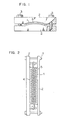
- Fig. 3 is a sectional view of a boiling water nuclear reactor;
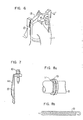
- Fig. 4 is a sectional view of a finger spring disposed between a channel box and a tie plate of a nuclear fuel assembly in a portion IV of the nuclear reactor shown in Fig. 3;
- Fig. 5 is a sectional view of an expansion spring adapted for fixing a graphite seal of a control rod driving mechanism provided at a portion V in the nuclear reactor shown in Fig. 3 to an index tube;
- Fig. 6 is a perspective view of a retainer beam extended between arms so as to press downwardly an elbow .pipe of a jet pump disposed at a portion VI of the nuclear reactor shown in Fig. 3;
- Fig. 7 is a sectional view of a cap screw for fixing a spring to a guard of the fuel assembly at a portion VII of the nuclear reactor shown in Fig. 3; .
- Fig. 8a is a perspective view of ,a garter spring for fixing a graphite seal to a piston tube; and
- Fig: 8b is a side elevational view of the garter spring in the state out of use.
- As stated before, the member in accordance with the invention can be practically embodied in the form of various parts incorporated in boiling water reactors, as will be understood from the following Table 1 showing the examples of application.

- Typical examples of the application will be explained hereinunder with reference to the accompanying drawings.
- Table 2 shows chemical compositions of typical examples of the alloy in accordance with the invention, together with the comparative materials.

- The alloys A to E of the invention-and the comparative alloys F to M have been produced by a process having the steps of making an ingot through a couple of vacuum melting, forming the ingot into a desired form through repetitional hot forging and diffusion heat treatment (soaking) and subjecting the formed materials to a predetermined heat treatment. The ingots were formed into a bar-like form by the vacuum melting. A vacuum arc melting was effected using the thus formed ingots as electrodes. The aforementioned X750 alloy is shown as the comparative material F.
- Table 3 shows the results of tests conducted with the alloys shown in Table 2, to examine the Vickers hardness (Hv) and the resistance to crevice constant-strain stress corrosion cracking in hot water. The test for examining the resistance to stress corrosion cracking mentioned above will be referred to as "crevice SCC test". The crevice SCC test was conducted in the following procedure.
- Plate-like test pieces of 10 mm wide and 2 mm thick were obtained from each alloy. The test piece 1 was clamped by a
holders 2 made of stainless steel (See Fig. 1) and bolts 3 were tightened to strongly press the test piece to impart thereto a uniform bending stress of 1%. Agraphite wool 4 was placed on the cocave side of the test piece to form a crevice. The test piece 1 in the stressed condition was then immersed in water of a high temperature. The water was a re-generated circulated pure water of 288°C containing 26 ppm of dissolved oxygen. After a continuous immersion for 500 hours, the cross-section of the test piece was observed by a microscope for a measurement of depths of cracks. - The alloys used in the test had microstructures consisting essentially of austenite phase matrix including one or both of the y' and y" phases.
- The cooling after the heating in each of the solution heat treatment and the aging treatment was conducted by air cooling.
- After the machining of each material into the form of test pieces, the test pieces were polished on their surfaces by #600 emery paper before subjected to the test.


- From Table 3, it will be seen that, while the alloys of the invention and the comparative alloys F, H, I exhibit sufficiently high hardnesses, the comparative alloy G having a small Nb content, comparative alloy L having a small Al content and the comparative alloy M having a small Ti content are not hardened sufficiently. Since the regulation requires that the spring materials used particularly in nuclear reactors have hardnesses greater than 300 Hv, the comparative alloy L apparently fails to meet this regulation.
- As to the crevice SCC test, the comparative alloys F to I showed deep cracks irrespective of the various aging conditions. In contrast, all of the alloys A to E in accordance with the invention showed high resistance to the crevice stress corrosion cracking.
- It is true that the resistance to crevice stress corrosion cracking is improved by increasing the Cr content also in the comparative alloys F to H. The effect of increase in Cr content, however, is small as compared with the alloys of the invention. This means that the increase in Cr content solely is insufficient and addition of Mo is essential for achieving a sufficiently high resistance to crevice stress corrosion cracking. On the other hand, it is also understood that, when the Nb content is increased beyond 5% as in the case of the comparative alloy I, cracks starting from coarse carbides or intermetallic compounds are easily formed. Further, the comparative alloy J having a Cr consent in excess of 25% and the comparative alloy K having an Mo content exceeding 8% exhibit unacceptably low forgibility, and embrittlement cracking due to the presence of TCP phase was observed in the aged alloy. Incidentally, the comparative alloy M could not be used in the crevice SCC test because of a too heavy cracking during being forged.
- Table 4 shows, in weight percent, the chemical compositions of alloy materials of a leaf spring in accordance with the invention, in comparison with those of reference alloy materials.

- The alloy materials were molten in the same manner as Example 1 and then shaped into the form of leaf springs by hot forging. The comparative alloy P and the comparative alloy Q correspond to the X750 alloy mentioned before and inconel 718 alloy, respectively. Test pieces obtained from these alloys were subjected to a crevice SCC test in hot water, in the same manner as Example 1. The sample alloys B, N, 0 and P were subjected to a solution heat treatment conducted at 1,060°C, while the sample alloy Q was subjected to a solution heat treatment conducted at 950°C. Subsequently, all sample alloys were subjected to a cold plastic work and then to an aging treatment. The surfaces of the aged materials were polished by #600 emery paper.

- Table 5 shows the results of tests conducted for examining the 0.2% proof stress at room temperature of a plurality of kinds of leaf springs produced from the alloy materials shown in Table 4 under different conditions of production, as well as the resistance to the crevice stress corrosion cracking of these leaf springs. The crevice SCC test was conducted with 10 (ten) test pieces for each kind of leaf spring, and the number of the test pieces exhibiting any crack out of 10 is shown in Table 5.
- From Table 5, it will be seen that the leaf springs in accordance with the invention showed high resistances to the crevice stress corrosion cracking. In fact, none of the test pieces of the leaf springs in accordance with the invention showed cracking. All of the test pieces which had been subjected to the cold plastic works of reduction in area greater than 20% showed 0.2% proof stress exceeding 100 Kg/cm2. Cracks were observed, however, in all of the test pieces of the comparative alloys.
- In accordance with the test result explained in connection with Example 2, a
finger spring 7 as shown in Fig. 4 and anexpansion spring 10 as shown in Fig. 5 were produced from the alloy N shown in Table 4. Incidentally, in these Figures, 5 represents a tie plate, 6 a channel box, 8 a graphite seal, and 9 an index tube. Each cf the spring material was subjected, as in the case of Example 1, to a solution heat treatment following a melting and hot forging, and then to a cold plastic work of a reduction in area of 30%. Then, after a smoothing of the surfaces by finishing rolls, the material was shaped by a cold press into the form of spring, and was subjected to an aging which was conducted at 700°C for 20 hours, followed by a final surface finishing treatment. - Coiled springs were produced from the alloys shown in Table 4 and were subjected to a crevice SCC test in hot water. The springs were formed by subjecting the material alloys to a solution heat treatment conducted at same temperatures as in Example 2 and, with or without a cold drawing of a reduction in area of 10%, to a coiling followed by an aging treatment.
- The crevice SCC test was conducted in a manner shown in Fig. 2. Namely, the test piece was stretched to a length 25% greater than the length in the free state, and was clamped at its both sides by
holders 2 made of a stainless steel, with layers ofgraphite wool 4 therebetween. The test piece was then immersed in a hot water for 1,000 hours as in the case of Example 1. The test piece, i.e. the coiled spring, is designated by areference numeral 5 in Fig. 2. - Table 6 shows the result of the crevice SCC test in relation to the conditions of the cold work and aging treatment. It will be seen from Table 6 that the test pieces of coiled spring in accordance with the invention showed no crevice corrosion cracking, while all of the comparative test pieces of coiled spring showed rupture or cracking.


- The alloy N shown in Table 4 was produced by melting and subjected to a subsequent hot forging in the same manner as Example 1. The alloy material was then formed by a die forging into a
retainer beam 13 of jet pump as shown in Fig. 6. Incidentally in this Figure, 11 represents an elbow pipe, and 12, 12' an arm. After the die forging, a solution heat treatment was conducted in the same manner as Example 2. Then, after a mechanical processing into the desired shape, an aging was conducted for 20 hours at 700°C, followed by a surface finishing treatment. - A
cap screw 16 as shown in Fig. 7, for fixing a spring 14 to aguard 15 of a nuclear fuel assembly, was produced from the alloy N shown in Table 4 by a thread rolling following a melting and a hot forging which are conducted in the same way as Example 1. After the thread rolling, a solution heat treatment, aging treatment and a surface finish treatment were conducted as in the case of Example 5. - With the knowledge of the test result of Example 4, a garter spring 19 as shown in Figs. 8a and 8b was produced from the alloy N shown in Table 4. Incidentally, in Fig. 8a, 17 represents a graphite seal, and 18 a piston tube. As in the case of Example 1, the alloy was subjected to a solution heat treatment following the melting and hot forging. Then, the material was subjected to a cold drawing of reduction in area of 10% to form a wire of about 0.4 mm dia. which was then formed into a coil of an outside diameter of about 1.2 mm. The coil was then subjected to an aging treatment conducted for 20 hours at 700°C.
- As has been described, according to the invention, it is possible to obtain members or parts to be mounted in nuclear reactors, the members or parts being made of Ni base alloys which exhibit a high resistance to stress corrosion cracking in water of a high temperature and pressure in the presence of crevice. The members in accordance with the invention, therefore, can be used safely for a longer period of time than the conventional ones in nuclear reactors.
Claims (21)

Applications Claiming Priority (2)
| Application Number | Priority Date | Filing Date | Title |
|---|---|---|---|
| JP55182132A JPS57123948A (en) | 1980-12-24 | 1980-12-24 | Austenite alloy with stress corrosion cracking resistance |
| JP182132/80 | 1980-12-24 |
Publications (3)
| Publication Number | Publication Date |
|---|---|
| EP0056480A2 true EP0056480A2 (en) | 1982-07-28 |
| EP0056480A3 EP0056480A3 (en) | 1982-08-11 |
| EP0056480B1 EP0056480B1 (en) | 1986-10-29 |
Family
ID=16112885
Family Applications (1)
| Application Number | Title | Priority Date | Filing Date |
|---|---|---|---|
| EP81110688A Expired EP0056480B1 (en) | 1980-12-24 | 1981-12-22 | Use of nickel base alloy having high resistance to stress corrosion cracking |
Country Status (5)
| Country | Link |
|---|---|
| US (1) | US4979995A (en) |
| EP (1) | EP0056480B1 (en) |
| JP (1) | JPS57123948A (en) |
| CA (1) | CA1186535A (en) |
| DE (1) | DE3175528D1 (en) |
Cited By (15)
| Publication number | Priority date | Publication date | Assignee | Title |
|---|---|---|---|---|
| EP0066361A3 (en) * | 1981-04-17 | 1983-01-19 | Huntington Alloys, Inc. | Corrosion resistant high strength nickel-based alloy |
| US4487743A (en) * | 1982-08-20 | 1984-12-11 | Huntington Alloys, Inc. | Controlled expansion alloy |
| EP0091279B1 (en) * | 1982-04-02 | 1986-12-10 | Hitachi, Ltd. | Ni-base alloy member and method of producing the same |
| US4685978A (en) * | 1982-08-20 | 1987-08-11 | Huntington Alloys Inc. | Heat treatments of controlled expansion alloy |
| EP0247577A1 (en) * | 1986-05-27 | 1987-12-02 | Carpenter Technology Corporation | Corrosion resistant age hardenable nickel-base alloy |
| EP0235075A3 (en) * | 1986-01-20 | 1988-09-21 | Mitsubishi Jukogyo Kabushiki Kaisha | Ni-based alloy and method for preparing same |
| US4788036A (en) * | 1983-12-29 | 1988-11-29 | Inco Alloys International, Inc. | Corrosion resistant high-strength nickel-base alloy |
| GB2291069A (en) * | 1994-07-13 | 1996-01-17 | Snecma | Method of manufacturing sheets made of alloy 718 for the superplastic forming of parts therefrom |
| US5556594A (en) * | 1986-05-30 | 1996-09-17 | Crs Holdings, Inc. | Corrosion resistant age hardenable nickel-base alloy |
| EP1945826A4 (en) * | 2005-11-07 | 2010-04-07 | Huntington Alloys Corp | HIGH RESISTANCE CORROSION RESISTANT ALLOY FOR OIL FIELD APPLICATIONS |
| KR101243406B1 (en) * | 2008-01-09 | 2013-03-13 | 뉴트리 가부시키가이샤 | Composition for reducing oxidative stress and/or side effects occurring during cancer chemotherapy or improving nutritional status during cancer chemotherapy |
| US9017490B2 (en) | 2007-11-19 | 2015-04-28 | Huntington Alloys Corporation | Ultra high strength alloy for severe oil and gas environments and method of preparation |
| EP2734655B1 (en) | 2012-06-11 | 2016-05-25 | Huntington Alloys Corporation | High-strength corrosion-resistant tubing for oil and gas completion and drilling applications, and process for manufacturing thereof |
| US10562708B2 (en) | 2016-05-23 | 2020-02-18 | Volta 24 Llc | Roller system having spaced apart external rotor motor |
| US11286115B2 (en) | 2019-08-13 | 2022-03-29 | Hilmot LLC | Conveyor with extended motor configuration |
Families Citing this family (20)
| Publication number | Priority date | Publication date | Assignee | Title |
|---|---|---|---|---|
| JPS58136736A (en) * | 1982-02-08 | 1983-08-13 | Hitachi Ltd | Ni alloy member |
| JPS59136443A (en) * | 1983-07-25 | 1984-08-06 | Hitachi Ltd | Bolt material with excellent stress corrosion cracking resistance |
| JPH0245517U (en) * | 1988-09-18 | 1990-03-28 | ||
| JPH02109319U (en) * | 1989-02-18 | 1990-08-31 | ||
| JPH0398421U (en) * | 1990-01-26 | 1991-10-14 | ||
| JPH0545634U (en) * | 1991-11-16 | 1993-06-18 | アイテツク株式会社 | Eyeglass lens holding frame connection structure |
| JPH05157998A (en) * | 1991-12-06 | 1993-06-25 | Murai:Kk | Joining method and spectacle frame |
| US5827377A (en) * | 1996-10-31 | 1998-10-27 | Inco Alloys International, Inc. | Flexible alloy and components made therefrom |
| WO2000003053A1 (en) * | 1998-07-09 | 2000-01-20 | Inco Alloys International, Inc. | Heat treatment for nickel-base alloys |
| DE60015728T2 (en) * | 1999-01-28 | 2005-11-03 | Sumitomo Electric Industries, Ltd. | HEAT-RESISTANT ALLOY WIRE |
| US6454885B1 (en) | 2000-12-15 | 2002-09-24 | Rolls-Royce Corporation | Nickel diffusion braze alloy and method for repair of superalloys |
| US6531002B1 (en) * | 2001-04-24 | 2003-03-11 | General Electric Company | Nickel-base superalloys and articles formed therefrom |
| JP4277113B2 (en) * | 2002-02-27 | 2009-06-10 | 大同特殊鋼株式会社 | Ni-base alloy for heat-resistant springs |
| JP3814822B2 (en) * | 2002-03-08 | 2006-08-30 | 三菱マテリアル株式会社 | Fins and tubes for high temperature heat exchangers |
| JP2005211303A (en) * | 2004-01-29 | 2005-08-11 | Olympus Corp | Endoscope |
| JP4409409B2 (en) * | 2004-10-25 | 2010-02-03 | 株式会社日立製作所 | Ni-Fe base superalloy, method for producing the same, and gas turbine |
| JP2010138476A (en) * | 2008-12-15 | 2010-06-24 | Toshiba Corp | Jet pump beam and method for manufacturing the same |
| US8313593B2 (en) * | 2009-09-15 | 2012-11-20 | General Electric Company | Method of heat treating a Ni-based superalloy article and article made thereby |
| DE102011054718B4 (en) * | 2011-10-21 | 2014-02-13 | Hitachi Power Europe Gmbh | Method for generating a voltage reduction in erected tube walls of a steam generator |
| ITVA20130061A1 (en) * | 2013-12-05 | 2015-06-06 | Foroni Spa | AGING BASE NICKEL BASE CONTAINING CHROME, MOLIBDENO, NIOBIO, TITANIUM; HAVING HIGH MECHANICAL CHARACTERISTICS AND HIGH RESISTANCE TO CORROSION IN AGGRESSIVE ENVIRONMENTS THAT CAN MEET IN THE WELLS FOR THE EXTRACTION OF OIL AND GAS NAT |
Family Cites Families (8)
| Publication number | Priority date | Publication date | Assignee | Title |
|---|---|---|---|---|
| US2744821A (en) * | 1951-12-13 | 1956-05-08 | Gen Electric | Iron base high temperature alloy |
| US3243287A (en) * | 1962-09-14 | 1966-03-29 | Crucible Steel Co America | Hot strength iron base alloys |
| GB1077685A (en) * | 1964-04-15 | 1967-08-02 | Special Metals Corp | Improved high strength nickel base alloy |
| GB1132724A (en) * | 1966-10-03 | 1968-11-06 | Wiggin & Co Ltd Henry | Nickel-chromium-iron alloys |
| FR2154871A5 (en) * | 1971-09-28 | 1973-05-18 | Creusot Loire | |
| FR2277901A2 (en) * | 1974-07-12 | 1976-02-06 | Creusot Loire | IMPROVEMENTS TO NICKEL-IRON-CHROME BASED ALLOYS, WITH STRUCTURAL HARDENING OBTAINED BY APPROPRIATE THERMAL TREATMENT |
| US4231795A (en) * | 1978-06-22 | 1980-11-04 | The United States Of America As Represented By The United States Department Of Energy | High weldability nickel-base superalloy |
| US4225363A (en) * | 1978-06-22 | 1980-09-30 | The United States Of America As Represented By The United States Department Of Energy | Method for heat treating iron-nickel-chromium alloy |
-
1980
- 1980-12-24 JP JP55182132A patent/JPS57123948A/en active Granted
-
1981
- 1981-12-22 EP EP81110688A patent/EP0056480B1/en not_active Expired
- 1981-12-22 DE DE8181110688T patent/DE3175528D1/en not_active Expired
- 1981-12-23 CA CA000393087A patent/CA1186535A/en not_active Expired
-
1989
- 1989-03-31 US US07/331,184 patent/US4979995A/en not_active Expired - Lifetime
Cited By (20)
| Publication number | Priority date | Publication date | Assignee | Title |
|---|---|---|---|---|
| EP0066361A3 (en) * | 1981-04-17 | 1983-01-19 | Huntington Alloys, Inc. | Corrosion resistant high strength nickel-based alloy |
| EP0091279B1 (en) * | 1982-04-02 | 1986-12-10 | Hitachi, Ltd. | Ni-base alloy member and method of producing the same |
| US4487743A (en) * | 1982-08-20 | 1984-12-11 | Huntington Alloys, Inc. | Controlled expansion alloy |
| US4685978A (en) * | 1982-08-20 | 1987-08-11 | Huntington Alloys Inc. | Heat treatments of controlled expansion alloy |
| US4788036A (en) * | 1983-12-29 | 1988-11-29 | Inco Alloys International, Inc. | Corrosion resistant high-strength nickel-base alloy |
| EP0235075A3 (en) * | 1986-01-20 | 1988-09-21 | Mitsubishi Jukogyo Kabushiki Kaisha | Ni-based alloy and method for preparing same |
| EP0247577A1 (en) * | 1986-05-27 | 1987-12-02 | Carpenter Technology Corporation | Corrosion resistant age hardenable nickel-base alloy |
| US5556594A (en) * | 1986-05-30 | 1996-09-17 | Crs Holdings, Inc. | Corrosion resistant age hardenable nickel-base alloy |
| EP0262673A3 (en) * | 1986-10-01 | 1989-12-06 | Inco Alloys International, Inc. | Corrosion resistant high strength nickel-base alloy |
| GB2291069B (en) * | 1994-07-13 | 1997-10-29 | Snecma | Method of manufacturing sheets made of alloy 718 for the superplastic forming of parts therefrom |
| GB2291069A (en) * | 1994-07-13 | 1996-01-17 | Snecma | Method of manufacturing sheets made of alloy 718 for the superplastic forming of parts therefrom |
| EP1945826A4 (en) * | 2005-11-07 | 2010-04-07 | Huntington Alloys Corp | HIGH RESISTANCE CORROSION RESISTANT ALLOY FOR OIL FIELD APPLICATIONS |
| US8133334B2 (en) | 2005-11-07 | 2012-03-13 | Huntington Alloys Corporation | Process for manufacturing high strength corrosion resistant alloy for oil patch applications |
| US9017490B2 (en) | 2007-11-19 | 2015-04-28 | Huntington Alloys Corporation | Ultra high strength alloy for severe oil and gas environments and method of preparation |
| US10100392B2 (en) | 2007-11-19 | 2018-10-16 | Huntington Alloys Corporation | Ultra high strength alloy for severe oil and gas environments and method of preparation |
| KR101243406B1 (en) * | 2008-01-09 | 2013-03-13 | 뉴트리 가부시키가이샤 | Composition for reducing oxidative stress and/or side effects occurring during cancer chemotherapy or improving nutritional status during cancer chemotherapy |
| EP2734655B1 (en) | 2012-06-11 | 2016-05-25 | Huntington Alloys Corporation | High-strength corrosion-resistant tubing for oil and gas completion and drilling applications, and process for manufacturing thereof |
| US10253382B2 (en) | 2012-06-11 | 2019-04-09 | Huntington Alloys Corporation | High-strength corrosion-resistant tubing for oil and gas completion and drilling applications, and process for manufacturing thereof |
| US10562708B2 (en) | 2016-05-23 | 2020-02-18 | Volta 24 Llc | Roller system having spaced apart external rotor motor |
| US11286115B2 (en) | 2019-08-13 | 2022-03-29 | Hilmot LLC | Conveyor with extended motor configuration |
Also Published As
| Publication number | Publication date |
|---|---|
| US4979995A (en) | 1990-12-25 |
| DE3175528D1 (en) | 1986-12-04 |
| JPS57123948A (en) | 1982-08-02 |
| JPS6358213B2 (en) | 1988-11-15 |
| CA1186535A (en) | 1985-05-07 |
| EP0056480B1 (en) | 1986-10-29 |
| EP0056480A3 (en) | 1982-08-11 |
Similar Documents
| Publication | Publication Date | Title |
|---|---|---|
| US4979995A (en) | Member made of nickel base alloy having high resistance to stress corrosion cracking and method of producing same | |
| EP1342807B1 (en) | Austenitic stainless steel tube and manufacturing method thereof | |
| EP2226406B1 (en) | Stainless austenitic low Ni alloy | |
| EP1357198B1 (en) | Austenitic stainless alloy excellent in high temperature strength and corrosion resistance, heat resistant pressurized parts, and the manufacturing method thereof | |
| US4512820A (en) | In-pile parts for nuclear reactor and method of heat treatment therefor | |
| US5000801A (en) | Wrought stainless steel having good corrosion resistance and a good resistance to corrosion in seawater | |
| EP0657558A1 (en) | Fe-base superalloy | |
| EP0091279B1 (en) | Ni-base alloy member and method of producing the same | |
| JPH06322489A (en) | Steel tube for boiler excellent in steam oxidation resistance | |
| CN111394663A (en) | Heat-resistant iron-based alloy and preparation method thereof | |
| US5000914A (en) | Precipitation-hardening-type ni-base alloy exhibiting improved corrosion resistance | |
| US4033767A (en) | Ductile corrosion resistant alloy | |
| JP6745050B2 (en) | Ni-based alloy and heat-resistant plate material using the same | |
| US2891858A (en) | Single phase austenitic alloy steel | |
| US5116570A (en) | Stainless maraging steel having high strength, high toughness and high corrosion resistance and it's manufacturing process | |
| JP4059156B2 (en) | Stainless steel for nuclear power | |
| EP1087028B1 (en) | High-chromium containing ferrite based heat resistant steel | |
| US5948182A (en) | Heat resisting steel | |
| JP2624224B2 (en) | Steam turbine | |
| JPH0327626B2 (en) | ||
| JP2000001754A (en) | Austenitic alloys and structures using them | |
| JP2689864B2 (en) | High toughness steel pipe | |
| JPH10128575A (en) | Tig weld metal and method for tig welding for high strength chromium-molybdenum steel | |
| EP0241553A1 (en) | High strength stainless steel, and process for its production | |
| JPH0770705A (en) | Austenitic stainless steel excellent in thermal expansion property |
Legal Events
| Date | Code | Title | Description |
|---|---|---|---|
| PUAI | Public reference made under article 153(3) epc to a published international application that has entered the european phase |
Free format text: ORIGINAL CODE: 0009012 |
|
| PUAL | Search report despatched |
Free format text: ORIGINAL CODE: 0009013 |
|
| AK | Designated contracting states |
Designated state(s): DE SE |
|
| AK | Designated contracting states |
Designated state(s): DE SE |
|
| 17P | Request for examination filed |
Effective date: 19821223 |
|
| GRAA | (expected) grant |
Free format text: ORIGINAL CODE: 0009210 |
|
| AK | Designated contracting states |
Kind code of ref document: B1 Designated state(s): DE SE |
|
| REF | Corresponds to: |
Ref document number: 3175528 Country of ref document: DE Date of ref document: 19861204 |
|
| PLBE | No opposition filed within time limit |
Free format text: ORIGINAL CODE: 0009261 |
|
| STAA | Information on the status of an ep patent application or granted ep patent |
Free format text: STATUS: NO OPPOSITION FILED WITHIN TIME LIMIT |
|
| 26N | No opposition filed | ||
| EAL | Se: european patent in force in sweden |
Ref document number: 81110688.9 |
|
| PGFP | Annual fee paid to national office [announced via postgrant information from national office to epo] |
Ref country code: SE Payment date: 19971009 Year of fee payment: 17 |
|
| PGFP | Annual fee paid to national office [announced via postgrant information from national office to epo] |
Ref country code: DE Payment date: 19980227 Year of fee payment: 17 |
|
| PG25 | Lapsed in a contracting state [announced via postgrant information from national office to epo] |
Ref country code: SE Free format text: LAPSE BECAUSE OF NON-PAYMENT OF DUE FEES Effective date: 19981223 |
|
| PG25 | Lapsed in a contracting state [announced via postgrant information from national office to epo] |
Ref country code: DE Free format text: LAPSE BECAUSE OF NON-PAYMENT OF DUE FEES Effective date: 19991001 |