EP0055852B1 - Method and apparatus for controlling combustion of gasified fuel - Google Patents
Method and apparatus for controlling combustion of gasified fuel Download PDFInfo
- Publication number
- EP0055852B1 EP0055852B1 EP81110782A EP81110782A EP0055852B1 EP 0055852 B1 EP0055852 B1 EP 0055852B1 EP 81110782 A EP81110782 A EP 81110782A EP 81110782 A EP81110782 A EP 81110782A EP 0055852 B1 EP0055852 B1 EP 0055852B1
- Authority
- EP
- European Patent Office
- Prior art keywords
- fuel
- flow rate
- combustor
- combustion
- gasified
- Prior art date
- Legal status (The legal status is an assumption and is not a legal conclusion. Google has not performed a legal analysis and makes no representation as to the accuracy of the status listed.)
- Expired
Links
Images


Classifications
-
- F—MECHANICAL ENGINEERING; LIGHTING; HEATING; WEAPONS; BLASTING
- F02—COMBUSTION ENGINES; HOT-GAS OR COMBUSTION-PRODUCT ENGINE PLANTS
- F02C—GAS-TURBINE PLANTS; AIR INTAKES FOR JET-PROPULSION PLANTS; CONTROLLING FUEL SUPPLY IN AIR-BREATHING JET-PROPULSION PLANTS
- F02C3/00—Gas-turbine plants characterised by the use of combustion products as the working fluid
- F02C3/20—Gas-turbine plants characterised by the use of combustion products as the working fluid using a special fuel, oxidant, or dilution fluid to generate the combustion products
- F02C3/26—Gas-turbine plants characterised by the use of combustion products as the working fluid using a special fuel, oxidant, or dilution fluid to generate the combustion products the fuel or oxidant being solid or pulverulent, e.g. in slurry or suspension
- F02C3/28—Gas-turbine plants characterised by the use of combustion products as the working fluid using a special fuel, oxidant, or dilution fluid to generate the combustion products the fuel or oxidant being solid or pulverulent, e.g. in slurry or suspension using a separate gas producer for gasifying the fuel before combustion
-
- F—MECHANICAL ENGINEERING; LIGHTING; HEATING; WEAPONS; BLASTING
- F02—COMBUSTION ENGINES; HOT-GAS OR COMBUSTION-PRODUCT ENGINE PLANTS
- F02C—GAS-TURBINE PLANTS; AIR INTAKES FOR JET-PROPULSION PLANTS; CONTROLLING FUEL SUPPLY IN AIR-BREATHING JET-PROPULSION PLANTS
- F02C9/00—Controlling gas-turbine plants; Controlling fuel supply in air- breathing jet-propulsion plants
- F02C9/26—Control of fuel supply
- F02C9/40—Control of fuel supply specially adapted to the use of a special fuel or a plurality of fuels
-
- F—MECHANICAL ENGINEERING; LIGHTING; HEATING; WEAPONS; BLASTING
- F23—COMBUSTION APPARATUS; COMBUSTION PROCESSES
- F23N—REGULATING OR CONTROLLING COMBUSTION
- F23N5/00—Systems for controlling combustion
- F23N5/003—Systems for controlling combustion using detectors sensitive to combustion gas properties
-
- F—MECHANICAL ENGINEERING; LIGHTING; HEATING; WEAPONS; BLASTING
- F23—COMBUSTION APPARATUS; COMBUSTION PROCESSES
- F23N—REGULATING OR CONTROLLING COMBUSTION
- F23N2221/00—Pretreatment or prehandling
- F23N2221/10—Analysing fuel properties, e.g. density, calorific
-
- F—MECHANICAL ENGINEERING; LIGHTING; HEATING; WEAPONS; BLASTING
- F23—COMBUSTION APPARATUS; COMBUSTION PROCESSES
- F23N—REGULATING OR CONTROLLING COMBUSTION
- F23N2223/00—Signal processing; Details thereof
- F23N2223/06—Sampling
-
- Y—GENERAL TAGGING OF NEW TECHNOLOGICAL DEVELOPMENTS; GENERAL TAGGING OF CROSS-SECTIONAL TECHNOLOGIES SPANNING OVER SEVERAL SECTIONS OF THE IPC; TECHNICAL SUBJECTS COVERED BY FORMER USPC CROSS-REFERENCE ART COLLECTIONS [XRACs] AND DIGESTS
- Y02—TECHNOLOGIES OR APPLICATIONS FOR MITIGATION OR ADAPTATION AGAINST CLIMATE CHANGE
- Y02E—REDUCTION OF GREENHOUSE GAS [GHG] EMISSIONS, RELATED TO ENERGY GENERATION, TRANSMISSION OR DISTRIBUTION
- Y02E20/00—Combustion technologies with mitigation potential
- Y02E20/16—Combined cycle power plant [CCPP], or combined cycle gas turbine [CCGT]
- Y02E20/18—Integrated gasification combined cycle [IGCC], e.g. combined with carbon capture and storage [CCS]
Definitions
- the present invention relates to a method and an apparatus for controlling combustion of gasified fuel as described in the pre-characterizing part of claim 1 and claim 7, respectively.
- Such method and apparatus are known from GB-A-2 036 290.
- An example of the system comprising combusting the gasified fuel for generating power is a coal-gasification power plant based on the prior art of oxidizing coal with air, and utilizing the resulting gasified fuel as a gas turbine fuel, on which the following description will be based.
- Fig. 1 shows a flow diagram illustrating one embodiment of a coal gasification power plant, to which the present invention is applied.
- the coal-gasification power plant comprises a combustion unit, a gas turbine unit, a generator unit and a coal gasification unit
- the combustion unit comprises a compressor 1 and a combustor 2.
- Air 4 is compressed by compressor 1 and compressed air 5 is led to combustor 2.
- Coal-gasifed fuel 18 generated in the coal gasification unit is also led to combustor 2 and combusted therein with air 5 as an oxidizing agent to produce combustion gas 7 at a high temperature and a high pressure.
- Combustion gas 7 is led to turbine 3 to drive it. Most of power generated by turbine 3 is consumed for revolution in generator 8 to generate electric power. A portion of the power generated by turbine 3 is consumed for revolution in compressor 1.
- Flue gas 9 from turbine 3 is led to a waste heat recovery boiler 10 to generate steam at a high temperature and a high pressure, and the generated steam is consumed for driving a steam turbine (not shown in the drawing) and then for revolution in a power generator (not shown in the drawing) connected to the steam turbine to generate electric power.
- the coal gasification power plant uses a gasified fuel produced in the coal gasification unit as a fuel in place of the conventional fuel of high heating value such as natural gas, light fuel oil or kerosene which will be hereinafter referred to as "natural gas, etc.”.
- coal gasification is based on thermal decomposition of coal at an elevated temperature to gasify it, and the example shown in Fig. 1 is based on combustion of a portion of coal with air and thermal decomposition of the remaining portion of coal by the resulting heat of combustion, which is called "gasification by partial oxidation".
- the coal gasification unit based on such partial oxidation of coal shown in Fig. 1 comprises a coal gasifier 11, a heat recovery boiler 12 and a gas purification apparatus 13.
- Raw material coal 14, air 15 as an oxidizing agent, and steam 16 for adjusting the gasification temperature and also enriching hydrogen in the gasified fuel by steam reforming are led to gasifier 11, where a portion of coal 14 is combusted with air 15 and the remaining portion of coal 14 is thermally decomposed by the resulting heat of combustion with temperature adjustment of steam 16, whereby gasified fuel 17 is generated as a coal gas containing hydrogen.
- Air 15 is a portion of air 5 extracted from the line from compressor 1 to combustor 2, and the extracted air is compressed by a boost-up compressor 6 and led to gasifier 11. In place of the extracted air 15, an oxygen-enriched gas from a free standing oxygen plant can be supplied thereto.
- the raw gas 17 generated in coal gasifier furnace 11 is led to heat recovery boiler 12, and heat-exchanged with a heat-exchanging medium therein to recover the sensible heat possessed by raw gas 17, for example, by generating steam.
- raw gas 17' is led to gas purification apparatus 13, where dusts contained in the gas, reaction products containing sulfur, nitrogen, etc. originating from coal such as H 2 S and NH 3 , and alkali metals such as Na, K, Ca, etc. generated in a vapor state are removed from the gas, whereby purified gas 18 is obtained.
- the purified gasified fuel 18 is led to combustor 2, as described above.
- the coal gasification power plant includes a fuel production unit and is characterized by power generation while producing the necessary fuel, as compared with the one using fuel of natural gas, etc.
- Heating value of coal-gasified fuel is 1/7 to 1/ 10 of that of natural gas, etc., because air as an oxidizing agent for coal and steam are used, so that inert gas such as N 2 , CO 2 , H 2 0, etc. are contained in the gasified fuel, and a portion of the coal is combusted at the gasification of coal to thermally decompose the remaining portion of coal by the resulting heat of combustion.
- the heating value of coal-gasified fuel is as low as 1,000-1,500 Kcal/Nm 3 .
- the minimum necessary heating value of low calorific fuel for maintaining stable combustion depends upon composition of fuel, particularly hydrogen content, structure of combustor and air-fuel ratio, and is 800-1,000 Kcal/Nm 3 according to the so far available results of relevant tests. In is known that combustion becomes unstable, or combustion is impossible to continue by blow-out, etc. below the minimum necessary heating value. Particularly, in the case of low load driving of a gas turbine, the air-fuel ratio becomes higher and fuel must be combusted in a lean state.
- Heating value, flow rate and temperature of coal-gasified fuel depends upon change in composition of coal, fluctuation in the load of coal gasifier change in the operating conditions of gas purification apparatus.
- the coal gasification unit must be operated at the same time when the gas turbine is to be driven.
- the heating value, temperature and flow rate of coal-gasified fuel change during the operation by change in operating conditions of the coal gasification unit or uneveness in quality of coal as a raw material.
- Combustion gas temperature Tg as a combustor outlet temperature in a gas turbine unit can be represented as below in a form of function by the following factors: wherein C a , C f and C g represent specific heats at constant pressure of air, fuel and combustion gas, respectively, G ao and G, represent flow rates of air at the compressor outlet and fuel, respectively; Ta, Tf, and Tg represent temperatures of air, fuel and combustion gas, respectively; H u represents heating value of fuel; and k is a constant, which can be represented by the following equation, if the flow rate of extracted air from the air to be led to the coal gasifier by the compressor is G Ex and if fuel flow rate G, is proportional to G ex :
- combustion gas temperature Tg is dependent only on the fuel flow rate G f .
- adjustment of combustion gas temperature Tg that is, load adjustment of gas turbine, can be made only by controlling the fuel flow rate G f , and very stable control can be carried out.
- combustion gas temperature Tg is a function of three variables, i.e. fuel temperature T f , heating value H u , and fuel flow rate G f , and cannot be effectively controlled only by simple detection and control of fuel flow rate G, as in the case of natural gas, etc.
- a higher fuel flow rate G f is required then that in the case of natural gas, etc., and thus fluctuation in fuel temperature T f , i.e. fluctuation in the sensible heat of fuel to be led to the combustor, gives a great influence upon the combustion gas temperature Tg.
- GB-A-2 036 290 discloses a method for controlling a fuel flow rate to main burner by sampling a portion of fuel to be supplied to the main burner, combusting the samples fuel, determining the resulting fuel gas composition or measuring the combustion gas temperature, thereby determining an optimum air-to-fuel ratio of the fuel, and controlling a fuel flow rate to the main burner on the basis of the air-to-fuel ratio.
- the overall energy mainly a calorific value
- an object of the invention is to provide a method and an apparatus for controlling combustion of gasified fuel, which allow to keep the burner output to a desired value, even if the overall energy of fuel to be used is changing.
- a fuel flow rate control valve 33 is provided in a sampled fuel line 19 for supplying gasified fuel to the combustor 2 for a gas turbine, and a detector unit 34 for detecting an energy level of gasified fuel is connected to sampled fuel line 19 through a sampling line 21.
- Signal converter 35 is connected to detector unit 34 at one end and to a flow rate computer 37for computing the flow rate of gasified fuel at the other end.
- Flow rate computer 37 is connected to a control master 36 at one end, and to a controller 38for a flow rate control valve 33 at the other end.
- a flow rate detector 39 is provided at the downstream side of flow rate control valve 33 and connected to controller 38. Detail of detector unit 34 is shown in Fig. 2B.
- Detector unit 34 comprises a sampling tube 20 provided in fuel supply line 19, sampling line 21 connected to the sampling tube, a pressure reduction valve 33 and an orifice 25 provided in the sampling line 21, an air line 22 connected to the outlet line of compressor 1 for turbine, a pressure reduction valve 24 and an orifice 26 provided in the air line, a combustor 27 for the sampled fuel, and a temperature detector 28 provided in the combustor.
- Sampling tube 20 has many perforations for suction thereon to sample, at the upstream side of combustor 2, a portion of gasified fuel to be led to combustor 2 shown in Fig. 1 as a sampled fuel.
- Sampling line 21 is covered with a heat-insulating material 21' to maintain the sampled fuel at the temperature prevailing at the sampling point.
- Pressure reduction valve 23 and orifice 25 provided in sampled fuel line 21 work to maintain the flow rate of sampled fuel constant even if the temperature of sampled fuel fluctuates.
- Air line 22 extracts a portion of compressed air from compressor 1 as combustion air for the sampled fuel.
- Pressure reduction valve 24 and orifice 26 provided in air line 22 work to maintain the flow rate of air constant even if the temperature of extracted combustion air fluctuates, and are also set to supply the necessary air for satisfactory combustion, even if an expected fluctuation in heating value of the sampled fuel becomes a maximum.
- Combustor 27 for the sampled fuel has an outer cylinder 27a and an inner cylinder 27b. Outer cylinder 27a is covered with a heat-insulating material 27c.
- the sampled fuel are combusted with the air at constant flow rates to produce combustion gas.
- the combustion gas produced in combustor 27 is led to waste heat recovery boiler 10 or the like shown in Fig. 1 to recover the heat. Waste heat recovery boiler or the like is operated substantially under the atmosphere, and consequently combustor 27 is kept under the atmosphere.
- Temperature detector 28 detect a temperature Tg R of combustion gas produced by the combustion of sampled fuel, and transmits the detected signal to signal converter 35.
- Temperature of combustion gas Tg R resulting from combustion of gasified fuel is a function of three variables, i.e. fuel temperature T f , fuel heating value H u and fuel flow rate G f , as given before by equation (1).
- a portion of gasified fuel to be supplied to combustor 2 is continuously sampled and combusted to detect the temperature of combustion gas TR and then an overall energy level H u ' of sensible heat and heating value possessed per unit weight of gasified fuel is determined from the temperature Tg R . That is, T 9 R ⁇ H u '.
- Signal converter 35 proportionally converts the signal of temperature of combustion gas T gR resulting from the combustion of sampled gas to an overall energy level H u ' of gasified fuel, and the energy level signal is transmitted to flow rate computer 37 of gasified fuel.
- Control master 36 transmits the signal of the output L required for turbine 3 of coal gasification power plant as shown in Fig. 1 to flow rate computer 37.
- Flow rate computer 37 computes a necessary fuel flow rate G fR for generating the required output L from the signal of the required output L and the energy level H u ' of gasified fuel, which fluctuates from time to time. That is, the flow rate computer computes the following equation: where f is a function to obtain a fuel flow rate G fR from H u ' and L. The signal of fuel flow rate G fR resulting from the computation is transmitted to controller 38.
- Controller 38 adjusts the degree of opening of fuel flow rate control valve 33 on the basis of the signal of fuel flow rate G fR from flow rate computer 37 to control an actual flow rate of gasified fuel to be led to combustor 2.
- Flow rate detector 39 detects controlled actual flow rate G f of gasified fuel and feeds back the detected flow rate signal to controller 38.
- FIG. 3 another embodiment of combustion control according to the present invention is shown, where a temperature-setting means 40 and other flow rate computer 41 than 37 are provided in addition to the members provided in the combustion control system shown in Figs. 2A and 2B.
- Temperature-setting means 40 sets a turbine inlet gas temperature Tg'from the required output L of turbine 3 transmitted from control master 36. It can be presumed that the required output L of turbine and the turbine inlet gas temperature Tg' are in a substantially proportional correlation therebetween. The set turbine inlet gas temperature Tg' is transmitted therefrom to flow rate computer 41.
- Flow rate computer 41 computes a fuel flow rate G IR from the set turbine inlet gas temperature Tg' and the signal of overall energy level H u ' of gasified fuel transmitted from signal converter 35 for converting the temperature of combustion gas T gR resulting from combustion of sampled fuel. That is, the flow rate computer computes the following equation: wherein f is a function to obtain a fuel flow rate from H u ' and T g '.
- the signal of computed fuel flow rate G fR is transmitted thereform to controller 38 and controls flow rate control valve 33 for gasified fuel on the basis of the signal of computed fuel flow rate G fR .
- the turbine output becomes very close to the required output L transmitted from control master 36, though not identical therewith, and stable operation can be carried out so that the actual turbine inlet gas temperature can approach the set temperature T g '
- Fig. 4 shows comparison of the case of detecting an overall energy level H u ' of gasified fuel and controlling a fuel flow rate G fR on the basis of the detected energy level according to the present invention, shown by dotted line, with the case of not controlling the fuel flow rate, shown by a full line with respect to turbine inlet gas temperature.
- turbine can be stably operated by detecting H u ' and controlling G fR .
- auxiliary fuel-charging system having a flow rate control valve 45 and a control system for the flow rate control valve 45 are provided in addition to the combustion control system for gasified fuel shown in Figs. 2A and 2B as well as Fig. 1.
- the auxiliary fuel charging system charges a fuel of high heating value such as light oil, kerosene, etc. to combustor 2 through an auxiliary fuel line 44, a flow rate control valve 45 and a nozzle 46 for auxiliary fuel to carry out auxiliary combustion.
- the control system for flow rate control valve 45 for auxiliary fuel comprises an extracted air flow rate detector 40, an air flow rate computer 41, an air-fuel ratio, computer 42 and an auxiliary fuel flow rate-setting means 43.
- Extracted air flow rate detector 40 detects a flow rate G EX of air extracted from compressor 1, compressed by boost-up compressor 6 and led to coal gasifier furnace 11 and the detected signal G EX is transmitted to air flow rate computer 41.
- Air flow rate computer 41 computes an air flow rate G, to combustor 2 from the predetected discharged air flow rate of compressor 1 and the detected extracted air flow rate G EX , and the computed signal G a is transmitted to air-fuel ratio computer 42.
- Air-fuel ratio computer 42 receives fuel flow rate G, from fuel flow rate detector 39 in addition to the air flow rate G., and computes air-fuel ratio G a /G f from these two input signals, and the computed signal G a /G f is transmitted to auxiliary fuel flow rate-setting means 43.
- Auxiliary fuel flow rate-setting means 43 receives the signal of overall energy level H u ' possessed per unit weight of gasified fuel from signal converter 35 and the signal of fuel flow rate G, from fuel flow rate detector 39 in addition to the signal of air-fuel ratio G a /G f . Computation in auxiliary fuel flow rate-setting means depends upon the structure of combustor 2, combustion characteristics, and properties of auxiliary fuel.
- Auxiliary fuel flow rate-setting means 43 computes the necessary minimum energy level H u 'I for maintaining combustion in combustor 2 from the air-fuel ratio G a /G f .
- auxiliary fuel flow rate-setting means 43 computes deficient energy level (H u 'I-H u ') G f from the necessary minimum energy level H u 'l for maintaining combustion in combustor 2, the overall energy level H u ' of gasified fuel, and the fuel flow rate G,, and further computes auxiliary fuel flow rate G fax on the basis of the dificient energy level (H u 'I-H u ') G f .
- Fig. 7 relations between the deficient energy level (H u 'I-H u ') G, and the auxiliary fuel flow rate G fax are shown.
- a flow rate G fax of the auxiliary fuel to be charged to combustor 2 can be obtained from the relations shown in Fig. 7.
- auxiliary fuel flow rate-setting means 43 The timing of charging the auxiliary fuel and its flow rate G fax are comuted by auxiliary fuel flow rate-setting means 43, as described above, and the computed signals are transmitted to auxiliary fuel flow rate control valve 45 to open the flow rate control valve 45 and also adjust its degree of opening.
- auxiliary fuel flow rate control valve 45 the auxiliary fuel is charged into combustor 2 at the necessary flow rate, so that unstable combustion due to fluctuations in the overall energy level of gasified fuel and blow-out due to deficient energy level can be completely prevented.
- FIG. 8 still other embodiment of combustion control according to the present invention is shown, where an overall energy level-modifying means 47 is provided in addition to the members of combustion control system shown in Fig. 5.
- overall energy level-modifying means 47 receives the signal of overall energy level H u ' of gasified fuel from signal converter 35 and the signal of auxiliary fuel flow rate G fax from auxiliary fuel flow rate-setting means 43, and computes the following equation on the basis of the two signals to obtain modified overall energy level H u ".
- H uax is the heating value of auxiliary fuel.
- the signal of modified overall energy level H u " obtained by the computation is transmitted to fuel flow rate computer 37 to modify fuel flow rate G, R from the required output L and modified overall energy level H u ", and controller 38 controls fuel flow rate control valve 33 on the basis of the modified flow rate to maintain total heat load developed by combustion in combustor 2 constant.
- controller 38 controls fuel flow rate control valve 33 on the basis of the modified flow rate to maintain total heat load developed by combustion in combustor 2 constant.
- the combustion can be carried out stably.
- the present invention is applicable not only to a system of gasifying coal and combusting the resulting gasified fuel, but also generally to a system using the resulting combustion gas as in an energy source for generating power.
- combustion of gasified fuel can be automatically controlled in accordance with fluctuation in temperature and heating value of gasified fuel from time to time, if necessary, by charging an auxiliary fuel to a combustor.
- total heat load developed by combustion of auxiliary fuel in a combustor can be controlled to the set value by modifying the flow rate of gasified fuel.
Landscapes
- Engineering & Computer Science (AREA)
- Chemical & Material Sciences (AREA)
- Combustion & Propulsion (AREA)
- Mechanical Engineering (AREA)
- General Engineering & Computer Science (AREA)
- Feeding And Controlling Fuel (AREA)
- Engine Equipment That Uses Special Cycles (AREA)
Description
- The present invention relates to a method and an apparatus for controlling combustion of gasified fuel as described in the pre-characterizing part of claim 1 and claim 7, respectively. Such method and apparatus are known from GB-A-2 036 290.
- An example of the system comprising combusting the gasified fuel for generating power is a coal-gasification power plant based on the prior art of oxidizing coal with air, and utilizing the resulting gasified fuel as a gas turbine fuel, on which the following description will be based.
- Fig. 1 shows a flow diagram illustrating one embodiment of a coal gasification power plant, to which the present invention is applied.
- As shown in Fig. 1, the coal-gasification power plant comprises a combustion unit, a gas turbine unit, a generator unit and a coal gasification unit, and the combustion unit comprises a compressor 1 and a
combustor 2.Air 4 is compressed by compressor 1 and compressedair 5 is led tocombustor 2. Coal-gasifedfuel 18 generated in the coal gasification unit is also led tocombustor 2 and combusted therein withair 5 as an oxidizing agent to produce combustion gas 7 at a high temperature and a high pressure. - Combustion gas 7 is led to turbine 3 to drive it. Most of power generated by turbine 3 is consumed for revolution in generator 8 to generate electric power. A portion of the power generated by turbine 3 is consumed for revolution in compressor 1.
-
Flue gas 9 from turbine 3 is led to a wasteheat recovery boiler 10 to generate steam at a high temperature and a high pressure, and the generated steam is consumed for driving a steam turbine (not shown in the drawing) and then for revolution in a power generator (not shown in the drawing) connected to the steam turbine to generate electric power. - The coal gasification power plant uses a gasified fuel produced in the coal gasification unit as a fuel in place of the conventional fuel of high heating value such as natural gas, light fuel oil or kerosene which will be hereinafter referred to as "natural gas, etc.".
- Generally, coal gasification is based on thermal decomposition of coal at an elevated temperature to gasify it, and the example shown in Fig. 1 is based on combustion of a portion of coal with air and thermal decomposition of the remaining portion of coal by the resulting heat of combustion, which is called "gasification by partial oxidation".
- The coal gasification unit based on such partial oxidation of coal, shown in Fig. 1 comprises a coal gasifier 11, a
heat recovery boiler 12 and agas purification apparatus 13. - Raw
material coal 14,air 15 as an oxidizing agent, and steam 16 for adjusting the gasification temperature and also enriching hydrogen in the gasified fuel by steam reforming are led to gasifier 11, where a portion ofcoal 14 is combusted withair 15 and the remaining portion ofcoal 14 is thermally decomposed by the resulting heat of combustion with temperature adjustment of steam 16, whereby gasifiedfuel 17 is generated as a coal gas containing hydrogen.Air 15 is a portion ofair 5 extracted from the line from compressor 1 tocombustor 2, and the extracted air is compressed by a boost-upcompressor 6 and led to gasifier 11. In place of the extractedair 15, an oxygen-enriched gas from a free standing oxygen plant can be supplied thereto. - The
raw gas 17 generated in coal gasifier furnace 11 is led toheat recovery boiler 12, and heat-exchanged with a heat-exchanging medium therein to recover the sensible heat possessed byraw gas 17, for example, by generating steam. - After the heat recovery, raw gas 17' is led to
gas purification apparatus 13, where dusts contained in the gas, reaction products containing sulfur, nitrogen, etc. originating from coal such as H2S and NH3, and alkali metals such as Na, K, Ca, etc. generated in a vapor state are removed from the gas, whereby purifiedgas 18 is obtained. The purified gasifiedfuel 18 is led tocombustor 2, as described above. - The coal gasification power plant includes a fuel production unit and is characterized by power generation while producing the necessary fuel, as compared with the one using fuel of natural gas, etc.
- Properties and characteristics of coal-gasified fuel for the coal gasification power plant are distinguished in the following points from those of natural gas, etc.
- (1) Heating value of coal-gasified fuel is 1/7 to 1/ 10 of that of natural gas, etc., because air as an oxidizing agent for coal and steam are used, so that inert gas such as N2, CO2, H20, etc. are contained in the gasified fuel, and a portion of the coal is combusted at the gasification of coal to thermally decompose the remaining portion of coal by the resulting heat of combustion. The heating value of coal-gasified fuel is as low as 1,000-1,500 Kcal/Nm3. In other words, it is necessary to increase the flow rate of gasified fuel to a combustor to produce a combustion gas at the same temperature as that obtained by combustion of natural gas, etc., because combustion is usually carried out in excess of air in the case of a gas turbine. Otherwise, combustion becomes unstable in the combustor.
- The minimum necessary heating value of low calorific fuel for maintaining stable combustion depends upon composition of fuel, particularly hydrogen content, structure of combustor and air-fuel ratio, and is 800-1,000 Kcal/Nm3 according to the so far available results of relevant tests. In is known that combustion becomes unstable, or combustion is impossible to continue by blow-out, etc. below the minimum necessary heating value. Particularly, in the case of low load driving of a gas turbine, the air-fuel ratio becomes higher and fuel must be combusted in a lean state.
- (2) Heating value, flow rate and temperature of coal-gasified fuel depends upon change in composition of coal, fluctuation in the load of coal gasifier change in the operating conditions of gas purification apparatus.
- Different from the case of using natural, gas, etc. as fuel, the coal gasification unit must be operated at the same time when the gas turbine is to be driven. The heating value, temperature and flow rate of coal-gasified fuel change during the operation by change in operating conditions of the coal gasification unit or uneveness in quality of coal as a raw material.
- Combustion gas temperature Tg as a combustor outlet temperature in a gas turbine unit can be represented as below in a form of function by the following factors:


- In the case of natural gas, etc. or gasified fuel obtained by gasification of low quality fuel with oxygen, k=0 in the above equation (2).
- Since in the case of natural, gas, etc. specific heats at constant pressure, Ca, C, and Cg, temperatures of air and fuel, Ta and Tf, and heating value Hu are substantially constant, the combustion gas temperature Tg is dependent only on the fuel flow rate Gf. Thus, adjustment of combustion gas temperature Tg, that is, load adjustment of gas turbine, can be made only by controlling the fuel flow rate Gf, and very stable control can be carried out.
- On the other hand, in the case of gasified fuel as in the present invention, heating value Hu and fuel temperature T, fluctuate as described above, and thus combustion gas temperature Tg is a function of three variables, i.e. fuel temperature Tf, heating value Hu, and fuel flow rate Gf, and cannot be effectively controlled only by simple detection and control of fuel flow rate G, as in the case of natural gas, etc. Particularly in the case of coal-gasified fuel, a higher fuel flow rate Gf is required then that in the case of natural gas, etc., and thus fluctuation in fuel temperature Tf, i.e. fluctuation in the sensible heat of fuel to be led to the combustor, gives a great influence upon the combustion gas temperature Tg.
- GB-A-2 036 290 mentioned in the beginning of the description discloses a method for controlling a fuel flow rate to main burner by sampling a portion of fuel to be supplied to the main burner, combusting the samples fuel, determining the resulting fuel gas composition or measuring the combustion gas temperature, thereby determining an optimum air-to-fuel ratio of the fuel, and controlling a fuel flow rate to the main burner on the basis of the air-to-fuel ratio. However, when the overall energy (mainly a calorific value) of fuel gas is changed, it is impossible to make control to keep the heat output of the main burner to a desired value.
- Accordingly, an object of the invention is to provide a method and an apparatus for controlling combustion of gasified fuel, which allow to keep the burner output to a desired value, even if the overall energy of fuel to be used is changing.
- According to the present invention this object is solved by the method described in claim 1 and by the apparatus described in claim 7.
- Particular embodiments of the invention are set out in the dependent claims.
- The present invention will be described in detail below, referring to the accompanying drawings wherein:
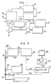
- Fig. 2A illustrates a flow diagram showing one embodiment of combustion control of gasified fuel according to the present invention, and Fig. 2B is a schematic view of a detector unit for detecting energy level of gasified fuel for carrying out the present invention.
- Fig. 3 is a flow diagram showing another embodiment of combustion control of gasified fuel according to the present invention.
- Fig. 4 is a diagram showing combustion characteristics of the case of controlling the flow rate of gasified fuel according to the present invention and the case of not controlling the flow rate of gasified fuel.
- Fig. 5 is a flow diagram showing another embodiment of combustion control of gasified fuel according to the present invention.
- Fig. 6 is a diagram showing relations between the air-fuel ratio of combustion air to gasified fuel to a combustor and the maximum necessary energy level as the limit level for maintaining combustion in the combustor at a given air-fuel ratio.
- Fig. 7 is a diagram showing relations between the deficient energy level of gasified fuel to a combustor and the flow rate of auxiliary fuel to be charged.
- Fig. 8 is a flow diagram showing still another embodiment of combustion control of gasified fuel according to the present invention.
- In Fig. 2A, one embodiment of combustion control according to the present invention is shown, where a fuel flow
rate control valve 33 is provided in a sampledfuel line 19 for supplying gasified fuel to thecombustor 2 for a gas turbine, and adetector unit 34 for detecting an energy level of gasified fuel is connected to sampledfuel line 19 through asampling line 21.Signal converter 35 is connected todetector unit 34 at one end and to a flow rate computer 37for computing the flow rate of gasified fuel at the other end.Flow rate computer 37 is connected to acontrol master 36 at one end, and to a controller 38for a flowrate control valve 33 at the other end. Aflow rate detector 39 is provided at the downstream side of flowrate control valve 33 and connected tocontroller 38. Detail ofdetector unit 34 is shown in Fig. 2B. -
Detector unit 34 comprises asampling tube 20 provided infuel supply line 19,sampling line 21 connected to the sampling tube, apressure reduction valve 33 and an orifice 25 provided in thesampling line 21, anair line 22 connected to the outlet line of compressor 1 for turbine, apressure reduction valve 24 and anorifice 26 provided in the air line, acombustor 27 for the sampled fuel, and atemperature detector 28 provided in the combustor. -
Sampling tube 20 has many perforations for suction thereon to sample, at the upstream side ofcombustor 2, a portion of gasified fuel to be led tocombustor 2 shown in Fig. 1 as a sampled fuel.Sampling line 21 is covered with a heat-insulating material 21' to maintain the sampled fuel at the temperature prevailing at the sampling point.Pressure reduction valve 23 and orifice 25 provided in sampledfuel line 21 work to maintain the flow rate of sampled fuel constant even if the temperature of sampled fuel fluctuates. -
Air line 22 extracts a portion of compressed air from compressor 1 as combustion air for the sampled fuel.Pressure reduction valve 24 andorifice 26 provided inair line 22 work to maintain the flow rate of air constant even if the temperature of extracted combustion air fluctuates, and are also set to supply the necessary air for satisfactory combustion, even if an expected fluctuation in heating value of the sampled fuel becomes a maximum. -
Combustor 27 for the sampled fuel has an outer cylinder 27a and aninner cylinder 27b. Outer cylinder 27a is covered with a heat-insulatingmaterial 27c. Incombustor 27, the sampled fuel are combusted with the air at constant flow rates to produce combustion gas. The combustion gas produced incombustor 27 is led to wasteheat recovery boiler 10 or the like shown in Fig. 1 to recover the heat. Waste heat recovery boiler or the like is operated substantially under the atmosphere, and consequently combustor 27 is kept under the atmosphere. -
Temperature detector 28 detect a temperature TgR of combustion gas produced by the combustion of sampled fuel, and transmits the detected signal to signalconverter 35. - Temperature of combustion gas TgR resulting from combustion of gasified fuel is a function of three variables, i.e. fuel temperature Tf, fuel heating value Hu and fuel flow rate Gf, as given before by equation (1).
- In the present invention, a portion of gasified fuel to be supplied to
combustor 2 is continuously sampled and combusted to detect the temperature of combustion gas TR and then an overall energy level Hu' of sensible heat and heating value possessed per unit weight of gasified fuel is determined from the temperature TgR. That is, T9R∝Hu'. - By determining an overall energy level Hu' of gasified fuel, fuel temperature Tf and heating value Hu can be determined among the variables determining the temperature of combustion gas TgR. Thus, unstable combustion due to fluctuation of heating value of gasified fuel and blow-out due to deficiency in heating value can be prevented by controlling an actual flow rate of gasified fuel on the basis of the overall energy level Hu' of gasified fuel.
-
Signal converter 35 proportionally converts the signal of temperature of combustion gas TgR resulting from the combustion of sampled gas to an overall energy level Hu' of gasified fuel, and the energy level signal is transmitted to flowrate computer 37 of gasified fuel. -
Control master 36 transmits the signal of the output L required for turbine 3 of coal gasification power plant as shown in Fig. 1 to flowrate computer 37.Flow rate computer 37 computes a necessary fuel flow rate GfR for generating the required output L from the signal of the required output L and the energy level Hu' of gasified fuel, which fluctuates from time to time. That is, the flow rate computer computes the following equation:
controller 38. -
Controller 38 adjusts the degree of opening of fuel flowrate control valve 33 on the basis of the signal of fuel flow rate GfR fromflow rate computer 37 to control an actual flow rate of gasified fuel to be led tocombustor 2. -
Flow rate detector 39 detects controlled actual flow rate Gf of gasified fuel and feeds back the detected flow rate signal tocontroller 38. - In Fig. 3, another embodiment of combustion control according to the present invention is shown, where a temperature-setting means 40 and other
flow rate computer 41 than 37 are provided in addition to the members provided in the combustion control system shown in Figs. 2A and 2B. - Temperature-setting means 40 sets a turbine inlet gas temperature Tg'from the required output L of turbine 3 transmitted from
control master 36. It can be presumed that the required output L of turbine and the turbine inlet gas temperature Tg' are in a substantially proportional correlation therebetween. The set turbine inlet gas temperature Tg' is transmitted therefrom to flowrate computer 41. -
Flow rate computer 41 computes a fuel flow rate GIR from the set turbine inlet gas temperature Tg' and the signal of overall energy level Hu' of gasified fuel transmitted fromsignal converter 35 for converting the temperature of combustion gas TgR resulting from combustion of sampled fuel. That is, the flow rate computer computes the following equation:
- The signal of computed fuel flow rate GfR is transmitted thereform to
controller 38 and controls flowrate control valve 33 for gasified fuel on the basis of the signal of computed fuel flow rate GfR. - In the embodiment shown in Fig. 3, the turbine output becomes very close to the required output L transmitted from
control master 36, though not identical therewith, and stable operation can be carried out so that the actual turbine inlet gas temperature can approach the set temperature Tg' - Structure and function of other members in the combustion control system shown in Fig. 3 are the same as shown in Figs. 2A and 2B, and other processes of combustion control based on the system shown in Fig. 3 are the same as shown in Figs. 2A and 2B.
- Fig. 4 shows comparison of the case of detecting an overall energy level Hu' of gasified fuel and controlling a fuel flow rate GfR on the basis of the detected energy level according to the present invention, shown by dotted line, with the case of not controlling the fuel flow rate, shown by a full line with respect to turbine inlet gas temperature. As is obvious from Fig. 4, turbine can be stably operated by detecting Hu' and controlling GfR.
- In Fig. 5, other embodiment of combustion control according to the present invention is shown, where an auxiliary fuel-charging system having a flow rate control valve 45 and a control system for the flow rate control valve 45 are provided in addition to the combustion control system for gasified fuel shown in Figs. 2A and 2B as well as Fig. 1. The auxiliary fuel charging system charges a fuel of high heating value such as light oil, kerosene, etc. to
combustor 2 through anauxiliary fuel line 44, a flow rate control valve 45 and anozzle 46 for auxiliary fuel to carry out auxiliary combustion. - The control system for flow rate control valve 45 for auxiliary fuel comprises an extracted air
flow rate detector 40, an airflow rate computer 41, an air-fuel ratio,computer 42 and an auxiliary fuel flow rate-setting means 43. - Extracted air
flow rate detector 40 detects a flow rate GEX of air extracted from compressor 1, compressed by boost-upcompressor 6 and led to coal gasifier furnace 11 and the detected signal GEX is transmitted to airflow rate computer 41. - Air
flow rate computer 41 computes an air flow rate G, tocombustor 2 from the predetected discharged air flow rate of compressor 1 and the detected extracted air flow rate GEX, and the computed signal Ga is transmitted to air-fuel ratio computer 42. - Air-
fuel ratio computer 42 receives fuel flow rate G, from fuelflow rate detector 39 in addition to the air flow rate G., and computes air-fuel ratio Ga/Gf from these two input signals, and the computed signal Ga/Gf is transmitted to auxiliary fuel flow rate-setting means 43. - Auxiliary fuel flow rate-setting means 43 receives the signal of overall energy level Hu' possessed per unit weight of gasified fuel from
signal converter 35 and the signal of fuel flow rate G, from fuelflow rate detector 39 in addition to the signal of air-fuel ratio Ga/Gf. Computation in auxiliary fuel flow rate-setting means depends upon the structure ofcombustor 2, combustion characteristics, and properties of auxiliary fuel. - Auxiliary fuel flow rate-setting means 43 computes the necessary minimum energy level Hu'I for maintaining combustion in
combustor 2 from the air-fuel ratio Ga/Gf. - In Fig. 6, relations between the air-fuel ratio Ga/ G, and the necessary minimum energy level Hu'I for maintaining combustion in
combustor 2 are in such relations as shown in Fig. 6, depending upon the characteristics of designedcombustor 2, and thus the necessary minimum energy level Hu'I for maintaining combustion incombustor 2 can be determined from the air-fuel ratio Ga/Gf. That is, a larger air-fuel ratio Ga/Gf brings the inside ofcombustor 2 into a fuel-defficient state and a fuel of a high energy level is required for maintaining the combustion, and the minimum energy level Hu'I is the necessary limit value for maintaining combustion incombustor 2. When the energy level Hu' of gasified fuel is lower than the necessary limit value, an auxiliary fuel is charged intocombustor 2. Timing of charging the auxilary fuel is determined as described above. - Then, auxiliary fuel flow rate-setting means 43 computes deficient energy level (Hu'I-Hu') Gf from the necessary minimum energy level Hu'l for maintaining combustion in
combustor 2, the overall energy level Hu' of gasified fuel, and the fuel flow rate G,, and further computes auxiliary fuel flow rate Gfax on the basis of the dificient energy level (Hu'I-Hu') Gf. - In Fig. 7 relations between the deficient energy level (Hu'I-Hu') G, and the auxiliary fuel flow rate Gfax are shown. By computing a dificient energy level (Hu'I-Hu') Gf, a flow rate Gfax of the auxiliary fuel to be charged to
combustor 2 can be obtained from the relations shown in Fig. 7. - The timing of charging the auxiliary fuel and its flow rate Gfax are comuted by auxiliary fuel flow rate-setting means 43, as described above, and the computed signals are transmitted to auxiliary fuel flow rate control valve 45 to open the flow rate control valve 45 and also adjust its degree of opening. Thus, the auxiliary fuel is charged into
combustor 2 at the necessary flow rate, so that unstable combustion due to fluctuations in the overall energy level of gasified fuel and blow-out due to deficient energy level can be completely prevented. - In Fig. 8 still other embodiment of combustion control according to the present invention is shown, where an overall energy level-modifying
means 47 is provided in addition to the members of combustion control system shown in Fig. 5. - When the overall energy level Hu' of gasified fuel becomes lower than the necessary minimum value for maintaining combustion in combustor2, an auxiliary fuel is charged into
combustor 2, as described above, and total heat load developed by combustion incombustor 2 is increased correspondingly by the charged auxiliary fuel. - In the embodiment shown in Fig. 8, overall energy level-modifying
means 47 receives the signal of overall energy level Hu' of gasified fuel fromsignal converter 35 and the signal of auxiliary fuel flow rate Gfax from auxiliary fuel flow rate-setting means 43, and computes the following equation on the basis of the two signals to obtain modified overall energy level Hu".
- The signal of modified overall energy level Hu" obtained by the computation is transmitted to fuel
flow rate computer 37 to modify fuel flow rate G,R from the required output L and modified overall energy level Hu", andcontroller 38 controls fuel flowrate control valve 33 on the basis of the modified flow rate to maintain total heat load developed by combustion incombustor 2 constant. Thus, the combustion can be carried out stably. - The present invention is applicable not only to a system of gasifying coal and combusting the resulting gasified fuel, but also generally to a system using the resulting combustion gas as in an energy source for generating power.
- Since a flow rate of gasified fuel to be led to a combustor is controlled in accordance with fluctuations in the overall energy level of gasified fuel according to the present invention, combustion of gasified fuel can be automatically controlled in accordance with fluctuation in temperature and heating value of gasified fuel from time to time, if necessary, by charging an auxiliary fuel to a combustor. Also, total heat load developed by combustion of auxiliary fuel in a combustor can be controlled to the set value by modifying the flow rate of gasified fuel. Thus, unstable combustion due to fluctuation in the heating value of gasified fuel and blow-out due to the deficient heating value can be effectively prevented, and a power-generating plant using the combustion gas of gasified fuel can be stably and continuously operated.
Claims (9)
Applications Claiming Priority (4)
| Application Number | Priority Date | Filing Date | Title |
|---|---|---|---|
| JP55185010A JPS57112611A (en) | 1980-12-27 | 1980-12-27 | Method and apparatus for controlling flow rate of gasified low grade fuel |
| JP185010/80 | 1980-12-27 | ||
| JP56000463A JPS57115617A (en) | 1981-01-07 | 1981-01-07 | Control of flow rate of auxiliary fuel in power plant or the like using low quality gasified fuel |
| JP463/81 | 1981-01-07 |
Publications (2)
| Publication Number | Publication Date |
|---|---|
| EP0055852A1 EP0055852A1 (en) | 1982-07-14 |
| EP0055852B1 true EP0055852B1 (en) | 1987-05-27 |
Family
ID=26333454
Family Applications (1)
| Application Number | Title | Priority Date | Filing Date |
|---|---|---|---|
| EP81110782A Expired EP0055852B1 (en) | 1980-12-27 | 1981-12-24 | Method and apparatus for controlling combustion of gasified fuel |
Country Status (3)
| Country | Link |
|---|---|
| US (1) | US4472936A (en) |
| EP (1) | EP0055852B1 (en) |
| DE (1) | DE3176219D1 (en) |
Families Citing this family (32)
| Publication number | Priority date | Publication date | Assignee | Title |
|---|---|---|---|---|
| US4785622A (en) * | 1984-12-03 | 1988-11-22 | General Electric Company | Integrated coal gasification plant and combined cycle system with air bleed and steam injection |
| US5174107A (en) * | 1989-07-06 | 1992-12-29 | Mitsubishi Jukogyo Kabushiki Kaisha | Combined power generating plant |
| JP2961913B2 (en) * | 1991-02-26 | 1999-10-12 | 株式会社日立製作所 | Combustion device and control method thereof |
| US5517818A (en) * | 1992-10-22 | 1996-05-21 | Evt Energie Und Verfahrenstechnick Gmbh | Gas generation apparatus |
| KR960700400A (en) * | 1992-12-30 | 1996-01-20 | 아더 이. 퍼니어 2세 | Control system for integrated gasification combined cycle system |
| FR2712961B1 (en) * | 1993-11-26 | 1995-12-22 | Lorraine Laminage | Real-time adjustment of a fuel burner with variable characteristics, in particular for metallurgical heating furnaces. |
| JP3196549B2 (en) * | 1995-01-09 | 2001-08-06 | 株式会社日立製作所 | Power generation system with fuel reformer |
| SE507116C2 (en) * | 1995-12-11 | 1998-03-30 | Abb Carbon Ab | Carburetor and power plant |
| CA2205766C (en) * | 1996-09-12 | 2001-02-20 | Mitsubishi Denki Kabushiki Kaisha | Combustion system and operation control method thereof |
| EP0884099A3 (en) * | 1997-06-09 | 2000-04-19 | Daido Hoxan Inc. | Gas generating apparatus and gas generation process using the same |
| JPH1162622A (en) * | 1997-08-22 | 1999-03-05 | Toshiba Corp | Integrated coal gasification combined cycle power plant and operation method |
| DE69817729T2 (en) * | 1997-11-04 | 2004-07-01 | Hitachi, Ltd. | gas turbine |
| WO2000014451A1 (en) * | 1998-09-10 | 2000-03-16 | Siemens Aktiengesellschaft | Method for operating a burner and burner arrangement |
| US6226976B1 (en) | 1999-02-26 | 2001-05-08 | Alliedsignal, Inc. | Variable fuel heating value adaptive control for gas turbine engines |
| JP4509267B2 (en) * | 1999-11-15 | 2010-07-21 | 日揮株式会社 | Oil fuel-fired combined power generation facility and method thereof |
| US6533925B1 (en) * | 2000-08-22 | 2003-03-18 | Texaco Development Corporation | Asphalt and resin production to integration of solvent deasphalting and gasification |
| US6430915B1 (en) | 2000-08-31 | 2002-08-13 | Siemens Westinghouse Power Corporation | Flow balanced gas turbine power plant |
| US6609378B2 (en) | 2002-01-17 | 2003-08-26 | Honeywell International Inc. | Energy based fuel control system for gas turbine engines running on multiple fuel types |
| US8156743B2 (en) * | 2006-05-04 | 2012-04-17 | General Electric Company | Method and arrangement for expanding a primary and secondary flame in a combustor |
| US7451591B2 (en) * | 2006-05-08 | 2008-11-18 | Econo-Power International Corporation | Production enhancements on integrated gasification combined cycle power plants |
| US7908864B2 (en) * | 2006-10-06 | 2011-03-22 | General Electric Company | Combustor nozzle for a fuel-flexible combustion system |
| US7874139B2 (en) * | 2006-10-13 | 2011-01-25 | Siemens Energy, Inc. | IGCC design and operation for maximum plant output and minimum heat rate |
| JP2008121513A (en) * | 2006-11-10 | 2008-05-29 | Mitsubishi Heavy Ind Ltd | Gas turbine power generation system and method of detecting calorie abnormality thereof |
| DE112007002785A5 (en) * | 2006-12-01 | 2009-11-05 | Alstom Technology Ltd. | Method for operating a gas turbine |
| US7950216B2 (en) * | 2007-01-30 | 2011-05-31 | Pratt & Whitney Canada Corp. | Gas turbine engine fuel control system |
| US7931466B2 (en) * | 2008-06-24 | 2011-04-26 | Equistar Chemicals, Lp | Flare gas flammability control |
| ITMI20090153A1 (en) * | 2009-02-06 | 2010-08-07 | Ansaldo Energia Spa | DEVICE AND METHOD TO ADJUST THE GAS SUPPLY TO A COMBUSTION CHAMBER AND GAS TURBINE SYSTEM INCLUDING SUCH A DEVICE |
| US9410481B2 (en) | 2010-09-21 | 2016-08-09 | 8 Rivers Capital, Llc | System and method for high efficiency power generation using a nitrogen gas working fluid |
| DE102011106373B4 (en) * | 2011-06-10 | 2017-02-09 | Vdeh-Betriebsforschungsinstitut Gmbh | Device for oxidizing the oxidizable fractions of a fuel gas sample for quality determination of the fuel gas |
| JP5804888B2 (en) * | 2011-10-19 | 2015-11-04 | 三菱日立パワーシステムズ株式会社 | Control method for gas turbine power plant, gas turbine power plant, control method for carbon-containing fuel gasifier, and carbon-containing fuel gasifier |
| US9410704B2 (en) * | 2013-06-03 | 2016-08-09 | General Electric Company | Annular strip micro-mixers for turbomachine combustor |
| JP6200731B2 (en) * | 2013-09-05 | 2017-09-20 | 三菱日立パワーシステムズ株式会社 | Control method of gasification power generation system |
Family Cites Families (13)
| Publication number | Priority date | Publication date | Assignee | Title |
|---|---|---|---|---|
| US2394297A (en) * | 1943-02-25 | 1946-02-05 | Lukens Steel Co | Furnace air control system |
| US2780414A (en) * | 1952-11-27 | 1957-02-05 | Stamicarbon | Heat input stabilization |
| US2829954A (en) * | 1954-11-30 | 1958-04-08 | Surface Combustion Corp | Apparatus for analyzing gas |
| US2931429A (en) * | 1956-12-26 | 1960-04-05 | Gen Electric | Dual fuel system for gas turbine powerplant |
| US3072468A (en) * | 1957-12-18 | 1963-01-08 | Ralph B Stitzer | Method and apparatus for detecting changes in the heating quality of fuel gas-air mixtures and for precise control thereof |
| GB1006431A (en) * | 1961-05-13 | 1965-09-29 | Zd Y V I Plzen | A method of and device for regulating the relative amount of burning components for gas burners |
| CH400427A (en) * | 1962-12-04 | 1965-10-15 | Sulzer Ag | Method and device for operating a combustion system charged with at least two different flowable fuels, in particular for a steam power plant or a gas turbine system |
| JPS4936452B1 (en) * | 1970-09-14 | 1974-10-01 | ||
| US3783684A (en) * | 1971-04-02 | 1974-01-08 | Bailey Controle | Fuel gas flow-meter corrector equipment for gases having variable characteristics |
| US4073619A (en) * | 1974-10-28 | 1978-02-14 | British Steel Corporation | Sampling gas for analysis |
| CH623888A5 (en) * | 1977-10-04 | 1981-06-30 | Bbc Brown Boveri & Cie | |
| GB1565310A (en) * | 1977-12-01 | 1980-04-16 | Battelle Development Corp | Method and apparatus for controlling fuel to oxidant ratioof a burner |
| GB2036290B (en) * | 1978-11-22 | 1982-12-01 | Hamworthy Engineering | Fuel sampling system |
-
1981
- 1981-12-24 US US06/334,175 patent/US4472936A/en not_active Expired - Fee Related
- 1981-12-24 EP EP81110782A patent/EP0055852B1/en not_active Expired
- 1981-12-24 DE DE8181110782T patent/DE3176219D1/en not_active Expired
Also Published As
| Publication number | Publication date |
|---|---|
| DE3176219D1 (en) | 1987-07-02 |
| EP0055852A1 (en) | 1982-07-14 |
| US4472936A (en) | 1984-09-25 |
Similar Documents
| Publication | Publication Date | Title |
|---|---|---|
| EP0055852B1 (en) | Method and apparatus for controlling combustion of gasified fuel | |
| US4489562A (en) | Method and apparatus for controlling a gasifier | |
| JP4745940B2 (en) | Coal gasification combined power generation system and operation control method thereof | |
| US4101632A (en) | Waste gas incineration control | |
| US4118172A (en) | Method and apparatus for controlling burner stoichiometry | |
| EP1211401B1 (en) | Fuel gas moisturization system control | |
| EP2080878B1 (en) | Gas turbine power generation system and method of detecting calorific abnormality of the same | |
| JPH09133321A (en) | Internal furnace condition forecasting method for pulverized coal combustion equipment and apparatus therefor | |
| JP5721317B2 (en) | Coal gasification furnace facility, control method and program thereof, and coal gasification combined power generation apparatus provided with the same | |
| JPH0342930B2 (en) | ||
| CN112664975A (en) | Air volume control method suitable for pulverized coal fired boiler | |
| US4569680A (en) | Gasifier with economizer gas exit temperature control | |
| JP3993472B2 (en) | Operation control method of gasification furnace for coal gasification combined power plant | |
| CN101014686B (en) | Gas reforming equipment | |
| JP6200731B2 (en) | Control method of gasification power generation system | |
| JP5804888B2 (en) | Control method for gas turbine power plant, gas turbine power plant, control method for carbon-containing fuel gasifier, and carbon-containing fuel gasifier | |
| WO2014175405A1 (en) | Gasification power plant control device, gasification power plant, and gasification power plant control method | |
| KR20150131385A (en) | Gasification power plant control device, gasification power plant, and gasification power plant control method | |
| JP2000120403A (en) | Integrated gas combined power generating system | |
| JP4009151B2 (en) | Combustion control method and apparatus for gasification melting furnace | |
| JP2000304234A (en) | Ash melting furnace and combustion control method therefor | |
| JPS638369B2 (en) | ||
| JP3646479B2 (en) | Coal gasification power plant | |
| CN113669753B (en) | Method, system and device for determining excess air coefficient of flame in hearth | |
| JPS63264696A (en) | Operation control method of coal gasifier oven |
Legal Events
| Date | Code | Title | Description |
|---|---|---|---|
| PUAI | Public reference made under article 153(3) epc to a published international application that has entered the european phase |
Free format text: ORIGINAL CODE: 0009012 |
|
| AK | Designated contracting states |
Designated state(s): DE FR GB |
|
| 17P | Request for examination filed |
Effective date: 19821007 |
|
| GRAA | (expected) grant |
Free format text: ORIGINAL CODE: 0009210 |
|
| AK | Designated contracting states |
Kind code of ref document: B1 Designated state(s): DE FR GB |
|
| REF | Corresponds to: |
Ref document number: 3176219 Country of ref document: DE Date of ref document: 19870702 |
|
| ET | Fr: translation filed | ||
| PLBE | No opposition filed within time limit |
Free format text: ORIGINAL CODE: 0009261 |
|
| STAA | Information on the status of an ep patent application or granted ep patent |
Free format text: STATUS: NO OPPOSITION FILED WITHIN TIME LIMIT |
|
| 26N | No opposition filed | ||
| PGFP | Annual fee paid to national office [announced via postgrant information from national office to epo] |
Ref country code: FR Payment date: 19931029 Year of fee payment: 13 |
|
| PGFP | Annual fee paid to national office [announced via postgrant information from national office to epo] |
Ref country code: GB Payment date: 19931214 Year of fee payment: 13 |
|
| PGFP | Annual fee paid to national office [announced via postgrant information from national office to epo] |
Ref country code: DE Payment date: 19940225 Year of fee payment: 13 |
|
| PG25 | Lapsed in a contracting state [announced via postgrant information from national office to epo] |
Ref country code: GB Effective date: 19941224 |
|
| GBPC | Gb: european patent ceased through non-payment of renewal fee |
Effective date: 19941224 |
|
| PG25 | Lapsed in a contracting state [announced via postgrant information from national office to epo] |
Ref country code: FR Effective date: 19950831 |
|
| PG25 | Lapsed in a contracting state [announced via postgrant information from national office to epo] |
Ref country code: DE Effective date: 19950901 |
|
| REG | Reference to a national code |
Ref country code: FR Ref legal event code: ST |