EP0055852A1 - Méthode et dispositif de contrôle de la combustion d'un carburant gazifié - Google Patents
Méthode et dispositif de contrôle de la combustion d'un carburant gazifié Download PDFInfo
- Publication number
- EP0055852A1 EP0055852A1 EP81110782A EP81110782A EP0055852A1 EP 0055852 A1 EP0055852 A1 EP 0055852A1 EP 81110782 A EP81110782 A EP 81110782A EP 81110782 A EP81110782 A EP 81110782A EP 0055852 A1 EP0055852 A1 EP 0055852A1
- Authority
- EP
- European Patent Office
- Prior art keywords
- fuel
- flow rate
- gasified fuel
- combustor
- combustion
- Prior art date
- Legal status (The legal status is an assumption and is not a legal conclusion. Google has not performed a legal analysis and makes no representation as to the accuracy of the status listed.)
- Granted
Links
Images


Classifications
-
- F—MECHANICAL ENGINEERING; LIGHTING; HEATING; WEAPONS; BLASTING
- F02—COMBUSTION ENGINES; HOT-GAS OR COMBUSTION-PRODUCT ENGINE PLANTS
- F02C—GAS-TURBINE PLANTS; AIR INTAKES FOR JET-PROPULSION PLANTS; CONTROLLING FUEL SUPPLY IN AIR-BREATHING JET-PROPULSION PLANTS
- F02C3/00—Gas-turbine plants characterised by the use of combustion products as the working fluid
- F02C3/20—Gas-turbine plants characterised by the use of combustion products as the working fluid using a special fuel, oxidant, or dilution fluid to generate the combustion products
- F02C3/26—Gas-turbine plants characterised by the use of combustion products as the working fluid using a special fuel, oxidant, or dilution fluid to generate the combustion products the fuel or oxidant being solid or pulverulent, e.g. in slurry or suspension
- F02C3/28—Gas-turbine plants characterised by the use of combustion products as the working fluid using a special fuel, oxidant, or dilution fluid to generate the combustion products the fuel or oxidant being solid or pulverulent, e.g. in slurry or suspension using a separate gas producer for gasifying the fuel before combustion
-
- F—MECHANICAL ENGINEERING; LIGHTING; HEATING; WEAPONS; BLASTING
- F02—COMBUSTION ENGINES; HOT-GAS OR COMBUSTION-PRODUCT ENGINE PLANTS
- F02C—GAS-TURBINE PLANTS; AIR INTAKES FOR JET-PROPULSION PLANTS; CONTROLLING FUEL SUPPLY IN AIR-BREATHING JET-PROPULSION PLANTS
- F02C9/00—Controlling gas-turbine plants; Controlling fuel supply in air- breathing jet-propulsion plants
- F02C9/26—Control of fuel supply
- F02C9/40—Control of fuel supply specially adapted to the use of a special fuel or a plurality of fuels
-
- F—MECHANICAL ENGINEERING; LIGHTING; HEATING; WEAPONS; BLASTING
- F23—COMBUSTION APPARATUS; COMBUSTION PROCESSES
- F23N—REGULATING OR CONTROLLING COMBUSTION
- F23N5/00—Systems for controlling combustion
- F23N5/003—Systems for controlling combustion using detectors sensitive to combustion gas properties
-
- F—MECHANICAL ENGINEERING; LIGHTING; HEATING; WEAPONS; BLASTING
- F23—COMBUSTION APPARATUS; COMBUSTION PROCESSES
- F23N—REGULATING OR CONTROLLING COMBUSTION
- F23N2221/00—Pretreatment or prehandling
- F23N2221/10—Analysing fuel properties, e.g. density, calorific
-
- F—MECHANICAL ENGINEERING; LIGHTING; HEATING; WEAPONS; BLASTING
- F23—COMBUSTION APPARATUS; COMBUSTION PROCESSES
- F23N—REGULATING OR CONTROLLING COMBUSTION
- F23N2223/00—Signal processing; Details thereof
- F23N2223/06—Sampling
-
- Y—GENERAL TAGGING OF NEW TECHNOLOGICAL DEVELOPMENTS; GENERAL TAGGING OF CROSS-SECTIONAL TECHNOLOGIES SPANNING OVER SEVERAL SECTIONS OF THE IPC; TECHNICAL SUBJECTS COVERED BY FORMER USPC CROSS-REFERENCE ART COLLECTIONS [XRACs] AND DIGESTS
- Y02—TECHNOLOGIES OR APPLICATIONS FOR MITIGATION OR ADAPTATION AGAINST CLIMATE CHANGE
- Y02E—REDUCTION OF GREENHOUSE GAS [GHG] EMISSIONS, RELATED TO ENERGY GENERATION, TRANSMISSION OR DISTRIBUTION
- Y02E20/00—Combustion technologies with mitigation potential
- Y02E20/16—Combined cycle power plant [CCPP], or combined cycle gas turbine [CCGT]
- Y02E20/18—Integrated gasification combined cycle [IGCC], e.g. combined with carbon capture and storage [CCS]
Definitions
- the present invention relates to a method and an apparatus for controlling combustion of gasified fuel in a system comprising gasifying a low quality fuel such as coal or heavy oil, combusting the gasified fuel and utilizing the combustion gas for generating power.
- gasifying a low quality fuel such as coal or heavy oil
- An example of the system comprising combusting the gasified fuel for generating power is a coal-gasification power plant based on the prior art of oxidizing coal with air, and utilizing the resulting gasified fuel as a gas turbine fuel, on which the following description will be based.
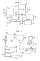
- the coal-gasification power plant comprises a combustion unit, a gas turbine unit, a generator unit and a coal gasification unit
- the combustion unit comprises a compressor 1 and a combustor 2.
- Air 4 is compressed by compressor 1, and compressed air 5 is led to combustor 2.
- Coal-gasified fuel 18 generated in the coal gasification unit is also led to combustor 2 and combusted therein with air 5 as an oxidizing agent to produce combustion gas 7 at a high temperature and a high pressure.
- Combustion gas ? is led to turbine 3 to drive it. Most of power generated by turbine 3 is consumed for revolution in generator 8 to generate electric power. A portion of the power generated by turbine 3 is consumed for revolution in compressor 1.
- Flue gas 9 from turbine 3 is led to a waste heat recovery boiler 10 to generate steam at a high temperature and a high pressure, and the generated steam is consumed for driving a steam turbine (not shown in the drawing) and then for revolution in a power generator (not shown in the drawing) connected to the steam turbine to generate electric power.
- the coal gasification power plant uses a gasified fuel produced in the coal gasification unit as a fuel in place of the conventional fuel of high heating value such as natural gas, light tuel oil or kerosence which will be hereinafter referred to as "natural gas, etc.”.
- coal gasification is based on thermal decomposition of coal at an elevated temperature to gasify it, and the example shown in Fig. 1 is based on combustion of a portion of coal with air and thermal decomposition of the remaining portion of coal by the resulting heat of combustion, which is called "gasification by partial oxidation".
- the coal gasification unit based on such partial oxidation of coal shown in Fig. 1 comprises a coal gasifier 11, a heat recovery boiler 12 and a gas purification apparatus 13.
- Raw material coal 14, air 15 as an oxidizing agent, and steam 16 for adjusting the gasification temperature and also enriching hydrogen in the gasified fuel by steam reforming are led to gasifier 11, where a portion of coal 14 is combusted with air 15 and the remaining portion of coal 14 is thermally decomposed by the resulting heat of combustion with temperature adjustment of steam 16, whereby gasified fuel 17 is generated as a coal gas containing hydrogen.
- Air 15 is a portion of air 5 extracted from the line from compressor 1 to combustor 2, and the extracted air is compressed by a boost-up compressor 6 and led to gasifier 11. In place of the extracted air 15, an oxygen-enriched gas from a free standing oxygen plant can be supplied thereto.
- the raw gas 17 generated in coal gasifier furnace 11 is led to heat recovery boiler 12, and heat- exchanged with a heat-exchanging medium therein to recover the sensible heat possessed by raw gas 17, for example, by generating steam.
- raw gas 17' is led to gas purification apparatus 13, where dusts contained in the gas, reaction products containing sulfur, nitrogen, etc. originating from coal such as H 2 S and NH 3 , and alkali metals such as Na, K, Ca, etc. generated in a vapor state are removed from the gas, whereby purified gas 18 is obtained.
- the purified gasified fuel 18 is led to combustor 2, as described above.
- the coal gasification power plant includes a fuel porduction unit and is characterized by power generation while producing the necessary fuel, as compared with the one using fuel of natural gas, etc.
- Heating value of coal-gasified fuel is 1/7 to 1/10 of that of natural gas, etc., because air as an oxidizing agent for coal and steam are used, so that inert gas such as N 2 , C0 23 H 2 0, etc. are contained in the gasified fuel, and a portion of the coal is combusted . at the gasification of coal to thermally decompose the remaining portion of coal by the resulting heat of combustion.
- the heating valve of coal-gasified fuel is as low as 1,000 - 1,500 Kcal/Nm3.
- the minimum necessary heating value of low calorific fuel for maintaining stable combustion depends upon composition of fuel, particularly hydrogen content, structure of combustor and air-fuel ratio, and is 800 - 1,000 Kcal/Nm 3 according to the so far available results of relevalent tests. It is known that combustion becomes unstable, or combustion is impossible to continue by blow-out, etc. below the minimum necessary heating value. Particularly, in the case of low load driving of a gas turbine, the air-fuel ratio becomes higher and fuel must be combusted in a lean state.
- Heating value, flow rate and temperature of coal-gasified fuel depends upon change in composition of coal, fluctuation in the load of coal gasifier change in the operating conditions of gas purification apparatus.
- the coal gasification unit must be operated at the same time when the gas turbine is to be driven.
- the heating value, temperature and flow rate of coal-gasified fuel change during the operation by change in operating conditions of the coal gasification unit or uneveness in quality of coal as a raw material.
- Combustion gas temperature T g as a combustor outlet temperature in a gas turbine unit can be represented as below in a form of function by the following factors: wherein C a , C f and C g represent specific heats at constant pressure of air, fuel and combustion gas, respectively, G ao and G f represent flow rates of air at the compressor outlet and fuel, respectively; Ta, Tf, and T g represent temperatures of air, fuel and combustion gas, respectively; H u represents heating value of fuel; and k is a constant, which can be represented by the following equation, if the flow rate of extracted air from the air to be led to the coal gasifier by the compressor is G EX and if fuel flow rate G f is proportional to G EX :
- combustion gas temperature T g is dependent only on the fuel flow rate G f .
- adjustment of combustion gas temeprature T that is, load adjustment of gas turbine, can be made only by controlling the fuel flow rate G f , and very stable control can be carried out.
- combustion gas temperature T g is a function of three variables, i.e. fuel temperature T f , heating value H u , and fuel flow rate G fi and cannot be effectively controlled only by simple detection and control of fuel flow rate G f as in the case of natural gas, etc.
- a higher fuel flow rate G f is required than that in the case of natural gas, etc., and thus fluctuation in fuel temperature T f' i.e. fluctuation in the sensible heat of fuel to be led to the combustor, gives a great influence upon the combustion gas temperature T .
- An object of the present invention is to solve the combustion control problem of gasified fuel encountered in a system comprising gasifying a low quality fuel such as coal or heavy oil, combusting the gasified fuel and utilizing the combustion gas for generating power, such as coal gasification power plant.
- Another object of the present invention is to prevent unstable combustion of gasified fuel due to fluctuation in the heating value of the gasified fuel and also to prevent blow-out of combustion due to the deficiency in the heating value.
- Another object of the present invention is to properly control the combustion of gasified fuel.
- the present invention provides a method for controlling combustion of gasified fuel in a process for combustion of gasified fuel by gasifying a low quality fuel and combusting the resulting gasified fuel in a combustor, which comprises continuously sampling a gasified fuel at a constant flow rate at the upstream side of the combustor, combusting the sampled gasified fuel, thereby detecting an overall energy level of sensible heat and heating value possessed per unit weight of the gasified fuel on the basis of a combustion temperature of the sampled gasified fuel, and controlling an actual flow rate of the gasified fuel to the combustor in accordance with fluctuations in the detected overall energy level.
- the resulting combustion gas in the combustor is utilized in a power-generating plant, for example, gas turbine, and a flow rate of the gasified fuel to the combustor is computed from the detected overall energy level and the required power output from the power-generating plant, and the actual flow rate of the gasified fuel is controlled in accordance with the computed flow rate.
- a power-generating plant for example, gas turbine
- an inlet gas temperatuer to the plant is set on the basis of the required power output of the power-generating plant, and a flow rate of gasified fuel to the combustor is computed from the set inlet gas temperature and the detected overall energy level possessed by the gasification fuel.
- the actual flow rate of the gasified fuel to the combustor is controlled in accordance with the computed flow rate.
- an auxiliary fuel is charged into the combustor and in accordance with the degree of lowering, and the computed flow rate of the gasified fuel is modified to control total heat load developed by combustion of the charged auxiliary fuel in the combustor to a set value.
- the present invention provides an apparatus for controlling combustion of gasified fuel in a system for combustion of gasified fuel comprising a gasification unit for a low quality fuel, and a combustor for combusting the gasified fuel generated from the gasification unit, thereby producing a combustion gas, which comprises a detector unit for continuously detecting an overall energy level of sensible heat and heating value possessed per unit weight of gasified fuel to be led to the combustor on the basis of a combustion temperature of the gasified fuel sampled at a constant flow rate at the upstream side of the combustor, and a control unit for controlling a flow rate control valve for the gasified fuel in accordance with fluctuations in the overall energy level detected by the detector unit.
- the present apparatus includes a system for charging an auxiliary fuel to the combustor through a flow rate control valve and a means for setting a flow rate of the auxiliary fuel by computing the necessary minimum energy level for maintaining combustion in the combustor from an air-fuel ratio of air to gasified fuel to the combustor, and setting timing of charging auxiliary fuel and its flow rate on the basis of the computed limit energy level, the overall energy level possessed per unit weight of gasified fuel and the computed flow rate of the gasified fuel, thereby controlling the flow rate control valve for the auxiliary fuel.
- the combustion gas is utilized in a power-generating plant, for example, a gas turbine unit
- the apparatus further includes a computing unit for computing a flow rate of gasified fuel to be led to the combustor from the overall energy level detected by the detector unit and the required output of the plant and a control unit for controlling the actual flow rate of gasified fuel to be led to the combustor on the basis of the computed flow rate.
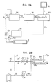
- a fuel flow rate control valve 33 is provided in a sampled fuel line 19 for supplying gasified fuel to the combustor 2 for a gas turbine, and a detector unit 34 for detecting an energy level of gasified fuel is connected to sampled fuel line 19 through a sampling line 21.
- Signal converter 35 is connected to detector unit 34 at one end and to a flow rate computer 37 for computing the flow rate of gasified fuel at the other end.
- Flow rate computer 37 is connected to a control master 36 at one end, and to a controller 38 for a flow rate control valve 33 at the other end.
- a flow rate detector 39 is provided at the downstream side of flow rate control valve 33 and connected to controller 38. Detail of detector unit 34 is shown in Fig. 2B.
- Detector unit 34 comprises a sampling tube 20 provided in fuel supply line 19, sampled fuel line connected to the sampling tube, a pressure reduction valve 23 and an orifice 25 provided in the sampled fuel line, an air line 22 connected to the outlet line of compressor 22 for turbine, a pressure reduction valve 24 and an orifice 26 provided in the air line, a combustor 27 for the sampled fuel, and a temperature detector 28 provided in the combustor.
- Sampling tube 20 has many perforations for suction thereon to sample, at the upstream side of combustor 2, a portion of gasified fuel to be led to combustor 2 shown in Fig. 1 as a sampled fuel.
- Sampled fuel line 21 is covered with a heat-insulating material 21' to maintain the sampled fuel at the temperature prevailing at the sampling point.
- Pressure reduction valve 23 and orifice 25 provided in sampled fuel line 21 work to maintain the flow rate of sampled fuel constant even if the temperature of sampled fuel fluctuates.
- Air line 22 extracts a portion of compressed air from compressor 1 as combustion air for the sampled - fuel.
- Pressure reduction valve 24 and orifice 26 provided in air line 22 work to maintain the flow rate of air constant even if the temperature of extracted combustion air fluctuates, and are also set to supply the necessary air for satisfactory combustion, even if an expected fluctuation in heating value of the sampled fuel becomes a maximum.
- Combustor 27 for the sampled fuel has an outer cylinder 27a and an inner cylinder 27b. Outer cylinder 27a is covered with a heat-insulating material 27c.
- the sampled fuel are combusted with the air at constant flow rates to produce combustion gas.
- the combustion gas produced in combustor 27 is led to waste heat recovery boiler 10 or the like shown in Fig. 1 to recover the heat. Waste heat recovery boiler or the like is operated substantially under the atmosphere, and consequently combustor 27 is kept under the atmosphere.
- Temperature detector 28 detect a temperature Tg R of combustion gas produced by the combustion of sampled fuel, and transmits the detected signal to signal converter 35.
- Temperature of combustion gas T g resulting from combustion of gasified fuel is a function of three variables, i.e. fuel temperatxre T f , fuel heating value H and fuel flow rate G f , as given before by equation (1).
- a portion of gasified fuel to be supplied to combustor 2 is continuously sampled and combusted to detect the temperature of combustion gas T gR and then an overall energy level H , of sensible heat and heating value posssessed per unit weight of gasified fuel is determined from the temperature Tg R . That is, T gr ⁇ H u' .
- Signal converter 35 proportionally converts the signal of temperature of combustion gas Tg R resulting from the combustion of sampled gas to an overall energy level H u , of gasified fuel, and the energy level signal is transmitted to flow rate computer 37 of gasified fuel.
- Control master 36 transmits the signal of the output L required for turbine 3 of coal gasification power plant as shown in Fig. 1 to flow rate computer 37.
- Flow rate computer 37 computes a necessary fuel flow rate G fR for generating the required output L from the signal of the required output L and the energy level H u' of gasified fuel, which fluctuates from time to time. That is, the flow rate computer computes the following equation: where f is a function to obtain a fuel flow rate G fR from H u' and L. The signal of fuel flow rate G fR resulting from the computation is transmitted to controller 38.
- Controller 38 adjusts the degree of opening of fuel flow rate control valve 33 on the basis of the signal of fuel flow rate G fR from flow rate computer 37 to control an actual flow rate of gasified fuel to be led to combustor 2.
- Flow rate detector 39 detects controlled actual flow rate G f of gasified fuel and feeds back the detected flow rate signal to controller 38.
- FIG. 3 another embodiment of combustion control according to the present invention is shown, where a temperature-setting means 40 and other flow rate computer 41 than 37 are provided in addition to the members provided in the combustion control system shown in Figs. 2A and 2B.
- Temperature-setting means 40 sets a turbine inlet gas temperature T , from the required output L of turbine 3 transmitted from control master 36. It can be presumed that the required output L of turbine and the turbine inlet gas temperature T g ' are in a substantially proportional correlation therebetween. The set turbine inlet gas temperature T g' is transmitted therefrom to.flow rate computer 41.
- Flow rate computer 41 computes a fuel flow rate G fR from the set turbine inlet gas temperature Tg, and the signal of overall energy level H , of gasified fuel transmitted from signal converter 35 for converting the temperature of combustion gas Tg R resutling from combustion of sampled fuel. That is, the flow rate computer computes the following equation: wherein f is a function to obtain a fuel flow rate'from H u' and T g '.
- the signal of computed fuel flow rate G fR is transmitted therefrom to controller 38 and controls flow rate control valve 33 for gasified fuel on the basis of the signal of computed fuel flow rate G fR .
- the turbine output becomes very close to the required output L transmitted from control master 36, though not identical therewith, and stable operation can be carried out so that the actual turbine inlet gas temperature can approach the set temperature T '.
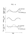
- Fig. 4 shows comparison of the case of detecting an overall energy level - H u' of gasified fuel and controlling a fuel flowrate G fR on the basis of the detected energy level according to the present invention, shown by dotted line, with the case of not controlling the fuel flow rate, shown by a full line with respect to turbine inlet gas temperature.
- turbine can be stably operated by detecting H u' and controlling G fR"
- auxiliary fuel-charging system having a flow rate control valve 45 and a control system for the flow rate control valve 45 are provided in addition to the combustion control system for gasified fuel shown in Figs. 2A and 2B as well as Fig. 1.
- the auxiliary fuel charging system charges a fuel of high heating value such as light oil, kerosene, etc. to combustor 2 through an auxiliary fuel line 44, a flow rate control valve 45 and a nozzle 46 for auxiliary fuel to carry out auxiliary combustion.
- the control system for flow rate control valve 45 for auxiliary fuel comprises an extracted air flow rate detector 40, an air flow rate computer 41, an air-fuel ratio computer 42 and an auxiliary fuel flow rate-setting means 43.
- Extracted air flow rate detector 40 detects a flow rate G EX of air extracted from compressor 1, compressed by boost-up compressor 6 and led to coal gasifier furnace 11 and the detected signal G EX is transmitted to air flow rate computer 41.
- Air flow rate computer 41 computes an air flow rate G to combustor 2 from the predetected a discharged air flow rate of compressor 1 and the detected extracted air flow rate G EX , and the computed signal G a is transmitted to air-fuel ratio computer 42.
- Air-fuel ratio computer 42 receives fuel flow rate G f from fuel flow rate detector 39 in addition to the air flow rate Ga, and computes air-fuel ratio G a /G f from these two input signals, and the computed signal G a /G f is transmitted to auxiliary fuel flow rate-setting means 43.
- Auxiliary fuel flow rate-setting means 43 receives the signal of overall energy level H u' possessed per unit weight of gasified fuel from signal converter 35 and the signal of fuel flow rate G f from fuel flow rate detector 39 in addition to the signal of air-fuel ratio G a /G f . Computation in auxiliary fuel flow rate-setting means depends upon the structure of combustor 2, combustion characteristics, and properties of auxiliary fuel.
- Auxiliary fuel flow rate-setting means 43 computes the necessary minimum heating value H u'1 for maintaining combustion in combustor 2 from the air-fuel ratio G a /G f .
- relations between the air-fuel ratio G a /G f and the necessary minimum heating value H u'1 for maintaining combustion in combustor 2 are in such relations as shown in Fig. 6, depending upon the characteristics of designed combustor 2, and thus the necessary minimum heating value H u'1 for maintaining combustion in combustor 2 can be determined from the air-fuel ratio G a /G f . That is, a larger air-fuel ratio G a /G f brings the inside of combustor 2 into a fuel- dificient state and a fuel of .a high energy level is required for maintaining the combustion, and the minimum heating value H u'1 is the necessary limit value for maintaining combustion in combustor 2. When the energy level H u' of gasified fuel is lower than the necessary limit value, an auxiliary fuel is charged into combustor 2. Timing of charging the auxiliary fuel is determined as described above.
- auxiliary fuel flow rate-setting means 43 computes deficient heating value (H u'1 - H u ,) G f from the Necessary minimum heating value H u'1 for maintaining combustion in combustor 2, the overall energy level H u' of gasified fuel, and the fuel flow rate G f3 and further computes auxiliary fuel flow rate G fax on the basis of the deficient heating value (H u , l - H u' ) G f .
- Fig. 7 relations between the deficient heating value (H u'1 - H u' ) G f and the auxiliary fuel flow rate G fax are shown.
- a flow rate G fax of the auxiliary fuel to be charged to combustor 2 can be obtained from the relations shown in Fig.7.
- auxiliary fuel flow rate-setting means 43 The timing of charging the auxilairy fuel and its flow rate G fax are computed by auxiliary fuel flow rate-setting means 43, as described above, and the computed signals are transmitted to auxiliary fuel flow rate control valve 45 to open the flow rate control valve 45 and also adjust its degree of opening.
- the auxiliary fuel is charged into combustor 2 at the necessary flow rate, so that unstable combustion due to fluctuations in the heating value of gasified fuel and blow-out due to deficient heating value can be completely prevented.
- FIG. 8 still other embodiment of combustion control according to the present invention is shown, where an overall energy level-modifying means 47 is provided in addition to the members of combustion control system shown in Fig. 5.
- overall energy level-modifying means 47 receives the signal of overall energy level H u' of gasified fuel from signal converter 35 and the signal of auxiliary fuel flow rate G fax from auxiliary fuel flow rate-setting means 43, and computes the following equation on the basis of the two signals to obtain modified overall energy level H u" .
- Huax is the heating value of auxiliary fuel.
- the signal of modified overall energy level H u" obtained by the computation is transmitted to fuel flow rate computer 37 to modify fuel flow rate G fR from the required output L and modified overall energy level H u" , and controller 38 controls fuel flow rate control valve 33 on the basis of the modified flow rate to maintain total heat load developed by combustion in combustor 2 constant.
- controller 38 controls fuel flow rate control valve 33 on the basis of the modified flow rate to maintain total heat load developed by combustion in combustor 2 constant.
- the combustion can be carried out stably.
- the present invention is applicable not only to a system of gasifying coal and combusting the resulting gasified fuel, but also generally to a system using the resulting combustion gas as an energy source for generating power.
- combustion of gasified fuel can be automatically controlled in accodance with fluctuation in temperature and heating value of gasified-fuel from time to time, if necessary, by charging an auxiliary fuel to a combustor.
- total heat load developed by combustion of auxiliary fuel in a .combustor can be controlled to the set value by modifying the flow rate of gasified fuel.
Landscapes
- Engineering & Computer Science (AREA)
- Chemical & Material Sciences (AREA)
- Combustion & Propulsion (AREA)
- Mechanical Engineering (AREA)
- General Engineering & Computer Science (AREA)
- Feeding And Controlling Fuel (AREA)
- Engine Equipment That Uses Special Cycles (AREA)
Applications Claiming Priority (4)
| Application Number | Priority Date | Filing Date | Title |
|---|---|---|---|
| JP55185010A JPS57112611A (en) | 1980-12-27 | 1980-12-27 | Method and apparatus for controlling flow rate of gasified low grade fuel |
| JP185010/80 | 1980-12-27 | ||
| JP463/81 | 1981-01-07 | ||
| JP56000463A JPS57115617A (en) | 1981-01-07 | 1981-01-07 | Control of flow rate of auxiliary fuel in power plant or the like using low quality gasified fuel |
Publications (2)
| Publication Number | Publication Date |
|---|---|
| EP0055852A1 true EP0055852A1 (fr) | 1982-07-14 |
| EP0055852B1 EP0055852B1 (fr) | 1987-05-27 |
Family
ID=26333454
Family Applications (1)
| Application Number | Title | Priority Date | Filing Date |
|---|---|---|---|
| EP81110782A Expired EP0055852B1 (fr) | 1980-12-27 | 1981-12-24 | Méthode et dispositif de contrôle de la combustion d'un carburant gazifié |
Country Status (3)
| Country | Link |
|---|---|
| US (1) | US4472936A (fr) |
| EP (1) | EP0055852B1 (fr) |
| DE (1) | DE3176219D1 (fr) |
Cited By (7)
| Publication number | Priority date | Publication date | Assignee | Title |
|---|---|---|---|---|
| EP0501313A1 (fr) * | 1991-02-26 | 1992-09-02 | Hitachi, Ltd. | Installation de combustion et procédé pour sa régulation |
| WO1994016210A1 (fr) * | 1992-12-30 | 1994-07-21 | Combustion Engineering, Inc. | Systeme de commande pour systeme de gazeification integree a cycle combine |
| FR2712961A1 (fr) * | 1993-11-26 | 1995-06-02 | Lorraine Laminage | Réglage en temps réel d'un brûleur à combustible de caractéristiques variables, notamment pour four métallurgique de réchauffage. |
| EP0829683A3 (fr) * | 1996-09-12 | 1999-03-10 | Mitsubishi Denki Kabushiki Kaisha | Système de combustion et procédé de commande de son fonctionnement |
| EP2080878A1 (fr) * | 2006-11-10 | 2009-07-22 | Mitsubishi Heavy Industries, Ltd. | Système de génération de puissance de turbine à gaz et procédé de détection de son anomalie de calorie |
| ITMI20090153A1 (it) * | 2009-02-06 | 2010-08-07 | Ansaldo Energia Spa | Dispositivo e metodo per regolare l'alimentazione di gas ad una camera di combustione e impianto a turbina a gas comprendente tale dispositivo |
| WO2012167914A3 (fr) * | 2011-06-10 | 2014-05-08 | Vdeh-Betriebsforschungsinstitut Gmbh | Dispositif d'oxydation des composants oxydables d'un échantillon de gaz combustible, afin de déterminer la qualité du gaz combustible |
Families Citing this family (25)
| Publication number | Priority date | Publication date | Assignee | Title |
|---|---|---|---|---|
| US4785622A (en) * | 1984-12-03 | 1988-11-22 | General Electric Company | Integrated coal gasification plant and combined cycle system with air bleed and steam injection |
| US5174107A (en) * | 1989-07-06 | 1992-12-29 | Mitsubishi Jukogyo Kabushiki Kaisha | Combined power generating plant |
| US5517818A (en) * | 1992-10-22 | 1996-05-21 | Evt Energie Und Verfahrenstechnick Gmbh | Gas generation apparatus |
| JP3196549B2 (ja) * | 1995-01-09 | 2001-08-06 | 株式会社日立製作所 | 燃料改質装置を備えた発電システム |
| SE507116C2 (sv) * | 1995-12-11 | 1998-03-30 | Abb Carbon Ab | Förgasningsanordning och kraftanläggning |
| CN1211534A (zh) * | 1997-06-09 | 1999-03-24 | 大同北产株式会社 | 气体发生装置及用它产生气体的方法 |
| JPH1162622A (ja) | 1997-08-22 | 1999-03-05 | Toshiba Corp | 石炭ガス化複合発電設備およびその運転方法 |
| US6199366B1 (en) * | 1997-11-04 | 2001-03-13 | Hitachi, Ltd. | Gas turbine |
| EP1112461B1 (fr) * | 1998-09-10 | 2004-04-14 | Siemens Aktiengesellschaft | Procede pour faire fonctionner un bruleur, et ensemble bruleur correspondant |
| US6226976B1 (en) | 1999-02-26 | 2001-05-08 | Alliedsignal, Inc. | Variable fuel heating value adaptive control for gas turbine engines |
| JP4509267B2 (ja) * | 1999-11-15 | 2010-07-21 | 日揮株式会社 | 石油燃料燃焼複合発電設備及びその方法 |
| US6533925B1 (en) * | 2000-08-22 | 2003-03-18 | Texaco Development Corporation | Asphalt and resin production to integration of solvent deasphalting and gasification |
| US6430915B1 (en) | 2000-08-31 | 2002-08-13 | Siemens Westinghouse Power Corporation | Flow balanced gas turbine power plant |
| US6609378B2 (en) | 2002-01-17 | 2003-08-26 | Honeywell International Inc. | Energy based fuel control system for gas turbine engines running on multiple fuel types |
| US8156743B2 (en) * | 2006-05-04 | 2012-04-17 | General Electric Company | Method and arrangement for expanding a primary and secondary flame in a combustor |
| US7451591B2 (en) * | 2006-05-08 | 2008-11-18 | Econo-Power International Corporation | Production enhancements on integrated gasification combined cycle power plants |
| US7908864B2 (en) * | 2006-10-06 | 2011-03-22 | General Electric Company | Combustor nozzle for a fuel-flexible combustion system |
| US7874139B2 (en) * | 2006-10-13 | 2011-01-25 | Siemens Energy, Inc. | IGCC design and operation for maximum plant output and minimum heat rate |
| JP5415276B2 (ja) * | 2006-12-01 | 2014-02-12 | アルストム テクノロジー リミテッド | ガスタービンを運転する方法 |
| US7950216B2 (en) * | 2007-01-30 | 2011-05-31 | Pratt & Whitney Canada Corp. | Gas turbine engine fuel control system |
| US7931466B2 (en) * | 2008-06-24 | 2011-04-26 | Equistar Chemicals, Lp | Flare gas flammability control |
| US9410481B2 (en) * | 2010-09-21 | 2016-08-09 | 8 Rivers Capital, Llc | System and method for high efficiency power generation using a nitrogen gas working fluid |
| JP5804888B2 (ja) * | 2011-10-19 | 2015-11-04 | 三菱日立パワーシステムズ株式会社 | ガスタービン発電プラントの制御方法、ガスタービン発電プラント、炭素含有燃料ガス化炉の制御方法及び炭素含有燃料ガス化炉 |
| US9410704B2 (en) * | 2013-06-03 | 2016-08-09 | General Electric Company | Annular strip micro-mixers for turbomachine combustor |
| JP6200731B2 (ja) * | 2013-09-05 | 2017-09-20 | 三菱日立パワーシステムズ株式会社 | ガス化発電システムの制御方法 |
Citations (7)
| Publication number | Priority date | Publication date | Assignee | Title |
|---|---|---|---|---|
| US2394297A (en) * | 1943-02-25 | 1946-02-05 | Lukens Steel Co | Furnace air control system |
| US2780414A (en) * | 1952-11-27 | 1957-02-05 | Stamicarbon | Heat input stabilization |
| US2829954A (en) * | 1954-11-30 | 1958-04-08 | Surface Combustion Corp | Apparatus for analyzing gas |
| GB1006431A (en) * | 1961-05-13 | 1965-09-29 | Zd Y V I Plzen | A method of and device for regulating the relative amount of burning components for gas burners |
| US3241597A (en) * | 1962-12-04 | 1966-03-22 | Sulzer Ag | Method of firing with fluid fuels |
| GB1565310A (en) * | 1977-12-01 | 1980-04-16 | Battelle Development Corp | Method and apparatus for controlling fuel to oxidant ratioof a burner |
| GB2036290A (en) * | 1978-11-22 | 1980-06-25 | Hamworthy Engineering | Fuel sampling system |
Family Cites Families (6)
| Publication number | Priority date | Publication date | Assignee | Title |
|---|---|---|---|---|
| US2931429A (en) * | 1956-12-26 | 1960-04-05 | Gen Electric | Dual fuel system for gas turbine powerplant |
| US3072468A (en) * | 1957-12-18 | 1963-01-08 | Ralph B Stitzer | Method and apparatus for detecting changes in the heating quality of fuel gas-air mixtures and for precise control thereof |
| JPS4936452B1 (fr) * | 1970-09-14 | 1974-10-01 | ||
| US3783684A (en) * | 1971-04-02 | 1974-01-08 | Bailey Controle | Fuel gas flow-meter corrector equipment for gases having variable characteristics |
| US4073619A (en) * | 1974-10-28 | 1978-02-14 | British Steel Corporation | Sampling gas for analysis |
| CH623888A5 (fr) * | 1977-10-04 | 1981-06-30 | Bbc Brown Boveri & Cie |
-
1981
- 1981-12-24 DE DE8181110782T patent/DE3176219D1/de not_active Expired
- 1981-12-24 EP EP81110782A patent/EP0055852B1/fr not_active Expired
- 1981-12-24 US US06/334,175 patent/US4472936A/en not_active Expired - Fee Related
Patent Citations (7)
| Publication number | Priority date | Publication date | Assignee | Title |
|---|---|---|---|---|
| US2394297A (en) * | 1943-02-25 | 1946-02-05 | Lukens Steel Co | Furnace air control system |
| US2780414A (en) * | 1952-11-27 | 1957-02-05 | Stamicarbon | Heat input stabilization |
| US2829954A (en) * | 1954-11-30 | 1958-04-08 | Surface Combustion Corp | Apparatus for analyzing gas |
| GB1006431A (en) * | 1961-05-13 | 1965-09-29 | Zd Y V I Plzen | A method of and device for regulating the relative amount of burning components for gas burners |
| US3241597A (en) * | 1962-12-04 | 1966-03-22 | Sulzer Ag | Method of firing with fluid fuels |
| GB1565310A (en) * | 1977-12-01 | 1980-04-16 | Battelle Development Corp | Method and apparatus for controlling fuel to oxidant ratioof a burner |
| GB2036290A (en) * | 1978-11-22 | 1980-06-25 | Hamworthy Engineering | Fuel sampling system |
Cited By (13)
| Publication number | Priority date | Publication date | Assignee | Title |
|---|---|---|---|---|
| EP0501313A1 (fr) * | 1991-02-26 | 1992-09-02 | Hitachi, Ltd. | Installation de combustion et procédé pour sa régulation |
| US5281129A (en) * | 1991-02-26 | 1994-01-25 | Hitachi, Ltd. | Combustion apparatus and control method therefor |
| WO1994016210A1 (fr) * | 1992-12-30 | 1994-07-21 | Combustion Engineering, Inc. | Systeme de commande pour systeme de gazeification integree a cycle combine |
| FR2712961A1 (fr) * | 1993-11-26 | 1995-06-02 | Lorraine Laminage | Réglage en temps réel d'un brûleur à combustible de caractéristiques variables, notamment pour four métallurgique de réchauffage. |
| EP0661499A1 (fr) * | 1993-11-26 | 1995-07-05 | Sollac S.A. | Réglage en temps réel d'un brûleur à gaz de caractéristiques variables, notamment pour four de réchauffage métallurgique |
| TR28665A (tr) * | 1993-11-26 | 1996-12-25 | Lorraine Laminage | Bilhassa bir metalörjik isitma ocagi icin, degisken özelliklere sahip bir gaz brülörünün hakiki zamanla ayarlanmasi. |
| EP0829683A3 (fr) * | 1996-09-12 | 1999-03-10 | Mitsubishi Denki Kabushiki Kaisha | Système de combustion et procédé de commande de son fonctionnement |
| US5957063A (en) * | 1996-09-12 | 1999-09-28 | Mitsubishi Denki Kabushiki Kaisha | Combustion system and operation control method thereof |
| EP2080878A1 (fr) * | 2006-11-10 | 2009-07-22 | Mitsubishi Heavy Industries, Ltd. | Système de génération de puissance de turbine à gaz et procédé de détection de son anomalie de calorie |
| EP2080878A4 (fr) * | 2006-11-10 | 2013-05-01 | Mitsubishi Heavy Ind Ltd | Système de génération de puissance de turbine à gaz et procédé de détection de son anomalie de calorie |
| ITMI20090153A1 (it) * | 2009-02-06 | 2010-08-07 | Ansaldo Energia Spa | Dispositivo e metodo per regolare l'alimentazione di gas ad una camera di combustione e impianto a turbina a gas comprendente tale dispositivo |
| WO2012167914A3 (fr) * | 2011-06-10 | 2014-05-08 | Vdeh-Betriebsforschungsinstitut Gmbh | Dispositif d'oxydation des composants oxydables d'un échantillon de gaz combustible, afin de déterminer la qualité du gaz combustible |
| DE102011106373B4 (de) * | 2011-06-10 | 2017-02-09 | Vdeh-Betriebsforschungsinstitut Gmbh | Vorrichtung zur Oxidation der oxidierbaren Anteile einer Brenngasprobe zur Qualitätsbestimmung des Brenngases |
Also Published As
| Publication number | Publication date |
|---|---|
| DE3176219D1 (en) | 1987-07-02 |
| US4472936A (en) | 1984-09-25 |
| EP0055852B1 (fr) | 1987-05-27 |
Similar Documents
| Publication | Publication Date | Title |
|---|---|---|
| US4472936A (en) | Method and apparatus for controlling combustion of gasified fuel | |
| US4489562A (en) | Method and apparatus for controlling a gasifier | |
| US5688296A (en) | Control system for IGCC's | |
| US4099374A (en) | Gasifier-combined cycle plant | |
| JP4745940B2 (ja) | 石炭ガス化複合発電システム及びその運転制御方法 | |
| US4631915A (en) | Gas turbine and steam power-generating plant with integrated coal gasification plant | |
| EP1211401B1 (fr) | Systéme réglage pour l'humidification d'un gas combustible | |
| JP5721317B2 (ja) | 石炭ガス化炉設備及びその制御方法並びにプログラム、及びこれを備えた石炭ガス化複合発電装置 | |
| RU2307946C2 (ru) | Система электроснабжения | |
| WO2008056790A1 (fr) | Système de génération de puissance de turbine à gaz et procédé de détection de son anomalie de calorie | |
| US4569680A (en) | Gasifier with economizer gas exit temperature control | |
| KR100847972B1 (ko) | 가스 개질 설비 | |
| JP3993472B2 (ja) | 石炭ガス化複合発電プラント用ガス化炉の運転制御方法 | |
| WO2013058253A1 (fr) | Procédé de commande d'une centrale à turbine à gaz, centrale à turbine à gaz, procédé de commande de four pour la gazéification d'un carburant contenant du carbone et four pour la gazéification d'un carburant contenant du carbone | |
| JP6200731B2 (ja) | ガス化発電システムの制御方法 | |
| KR101735989B1 (ko) | 가스화 발전 플랜트의 제어 장치, 가스화 발전 플랜트, 및 가스화 발전 플랜트의 제어 방법 | |
| JP4095829B2 (ja) | チャー循環型の石炭ガス化発電プラントシステム | |
| JP3977890B2 (ja) | ガス化発電システム | |
| JP2000120403A (ja) | ガス化複合発電システム | |
| US11292975B2 (en) | Powder fuel supply apparatus, gasfier unit, integrated gasification combined cycle, and control method of powder fuel supply apparatus | |
| JPS638369B2 (fr) | ||
| JP2007170245A (ja) | ガスタービン設備、低カロリガス供給設備および当該ガスのカロリ上昇抑制方法 | |
| JP3646479B2 (ja) | 石炭ガス化発電プラント | |
| JP2000304234A (ja) | 灰溶融炉及びその燃焼制御方法 | |
| JPS63264696A (ja) | 石炭ガス化炉の運転制御方法 |
Legal Events
| Date | Code | Title | Description |
|---|---|---|---|
| PUAI | Public reference made under article 153(3) epc to a published international application that has entered the european phase |
Free format text: ORIGINAL CODE: 0009012 |
|
| AK | Designated contracting states |
Designated state(s): DE FR GB |
|
| 17P | Request for examination filed |
Effective date: 19821007 |
|
| GRAA | (expected) grant |
Free format text: ORIGINAL CODE: 0009210 |
|
| AK | Designated contracting states |
Kind code of ref document: B1 Designated state(s): DE FR GB |
|
| REF | Corresponds to: |
Ref document number: 3176219 Country of ref document: DE Date of ref document: 19870702 |
|
| ET | Fr: translation filed | ||
| PLBE | No opposition filed within time limit |
Free format text: ORIGINAL CODE: 0009261 |
|
| STAA | Information on the status of an ep patent application or granted ep patent |
Free format text: STATUS: NO OPPOSITION FILED WITHIN TIME LIMIT |
|
| 26N | No opposition filed | ||
| PGFP | Annual fee paid to national office [announced via postgrant information from national office to epo] |
Ref country code: FR Payment date: 19931029 Year of fee payment: 13 |
|
| PGFP | Annual fee paid to national office [announced via postgrant information from national office to epo] |
Ref country code: GB Payment date: 19931214 Year of fee payment: 13 |
|
| PGFP | Annual fee paid to national office [announced via postgrant information from national office to epo] |
Ref country code: DE Payment date: 19940225 Year of fee payment: 13 |
|
| PG25 | Lapsed in a contracting state [announced via postgrant information from national office to epo] |
Ref country code: GB Effective date: 19941224 |
|
| GBPC | Gb: european patent ceased through non-payment of renewal fee |
Effective date: 19941224 |
|
| PG25 | Lapsed in a contracting state [announced via postgrant information from national office to epo] |
Ref country code: FR Effective date: 19950831 |
|
| PG25 | Lapsed in a contracting state [announced via postgrant information from national office to epo] |
Ref country code: DE Effective date: 19950901 |
|
| REG | Reference to a national code |
Ref country code: FR Ref legal event code: ST |