EP0055230B1 - Fluidized bed calcining furnace, particularly for regenerating sands used in casting boxes and cores - Google Patents
Fluidized bed calcining furnace, particularly for regenerating sands used in casting boxes and cores Download PDFInfo
- Publication number
- EP0055230B1 EP0055230B1 EP81830248A EP81830248A EP0055230B1 EP 0055230 B1 EP0055230 B1 EP 0055230B1 EP 81830248 A EP81830248 A EP 81830248A EP 81830248 A EP81830248 A EP 81830248A EP 0055230 B1 EP0055230 B1 EP 0055230B1
- Authority
- EP
- European Patent Office
- Prior art keywords
- air
- combustible gas
- bed
- base plate
- furnace
- Prior art date
- Legal status (The legal status is an assumption and is not a legal conclusion. Google has not performed a legal analysis and makes no representation as to the accuracy of the status listed.)
- Expired
Links
- 238000001354 calcination Methods 0.000 title abstract description 5
- 238000005266 casting Methods 0.000 title abstract description 5
- 230000001172 regenerating effect Effects 0.000 title abstract description 3
- 239000002245 particle Substances 0.000 claims abstract description 13
- 238000002156 mixing Methods 0.000 claims description 8
- 239000000203 mixture Substances 0.000 claims description 6
- 230000000284 resting effect Effects 0.000 claims description 2
- 239000007789 gas Substances 0.000 description 27
- 239000000463 material Substances 0.000 description 6
- 239000004576 sand Substances 0.000 description 3
- 238000009827 uniform distribution Methods 0.000 description 3
- 229910000746 Structural steel Inorganic materials 0.000 description 2
- 229910010293 ceramic material Inorganic materials 0.000 description 2
- 238000001816 cooling Methods 0.000 description 2
- 230000002093 peripheral effect Effects 0.000 description 2
- 239000011248 coating agent Substances 0.000 description 1
- 238000000576 coating method Methods 0.000 description 1
- 238000002485 combustion reaction Methods 0.000 description 1
- 238000010276 construction Methods 0.000 description 1
- 238000007599 discharging Methods 0.000 description 1
- 239000000835 fiber Substances 0.000 description 1
- 238000005243 fluidization Methods 0.000 description 1
- 239000008246 gaseous mixture Substances 0.000 description 1
- 238000003780 insertion Methods 0.000 description 1
- 230000037431 insertion Effects 0.000 description 1
- 239000002184 metal Substances 0.000 description 1
- 229910052751 metal Inorganic materials 0.000 description 1
- 230000008929 regeneration Effects 0.000 description 1
- 238000011069 regeneration method Methods 0.000 description 1
- 238000011144 upstream manufacturing Methods 0.000 description 1
Images


Classifications
-
- F—MECHANICAL ENGINEERING; LIGHTING; HEATING; WEAPONS; BLASTING
- F27—FURNACES; KILNS; OVENS; RETORTS
- F27B—FURNACES, KILNS, OVENS, OR RETORTS IN GENERAL; OPEN SINTERING OR LIKE APPARATUS
- F27B15/00—Fluidised-bed furnaces; Other furnaces using or treating finely-divided materials in dispersion
- F27B15/02—Details, accessories, or equipment peculiar to furnaces of these types
- F27B15/10—Arrangements of air or gas supply devices
-
- B—PERFORMING OPERATIONS; TRANSPORTING
- B01—PHYSICAL OR CHEMICAL PROCESSES OR APPARATUS IN GENERAL
- B01J—CHEMICAL OR PHYSICAL PROCESSES, e.g. CATALYSIS OR COLLOID CHEMISTRY; THEIR RELEVANT APPARATUS
- B01J8/00—Chemical or physical processes in general, conducted in the presence of fluids and solid particles; Apparatus for such processes
- B01J8/18—Chemical or physical processes in general, conducted in the presence of fluids and solid particles; Apparatus for such processes with fluidised particles
- B01J8/1818—Feeding of the fluidising gas
- B01J8/1827—Feeding of the fluidising gas the fluidising gas being a reactant
-
- F—MECHANICAL ENGINEERING; LIGHTING; HEATING; WEAPONS; BLASTING
- F23—COMBUSTION APPARATUS; COMBUSTION PROCESSES
- F23C—METHODS OR APPARATUS FOR COMBUSTION USING FLUID FUEL OR SOLID FUEL SUSPENDED IN A CARRIER GAS OR AIR
- F23C10/00—Fluidised bed combustion apparatus
- F23C10/18—Details; Accessories
- F23C10/20—Inlets for fluidisation air, e.g. grids; Bottoms
-
- F—MECHANICAL ENGINEERING; LIGHTING; HEATING; WEAPONS; BLASTING
- F23—COMBUSTION APPARATUS; COMBUSTION PROCESSES
- F23C—METHODS OR APPARATUS FOR COMBUSTION USING FLUID FUEL OR SOLID FUEL SUSPENDED IN A CARRIER GAS OR AIR
- F23C10/00—Fluidised bed combustion apparatus
- F23C10/18—Details; Accessories
- F23C10/22—Fuel feeders specially adapted for fluidised bed combustion apparatus
Definitions
- the present invention relates to furnaces with fluidized beds.
- the invention relates to a furnace of the type comprising a bed of refractory particles and means for supplying a combustible gas and air to the bed so as to enable the combustible gas to burn within the bed and to fluidize the bed, said furnace including a base plate which supports the bed of refractory particles, the said means for supplying air comprising a plurality of holes formed in the base plate through which the air is fed into the bed, and said means for supplying the combustible gas comprising a plurality of nozzles disposed coaxially within the said holes, each nozzle having at least one discharge aperture for the combustible gas, located substantially in the plane of the base plate, wherein within each hole of the base plate is fixed a tubular air-supply element surrounding the respective supply nozzle for the combustible gas.
- a furnace having the structure indicated above is known from DE-A-1 813 286.
- the combustible gas and the air are introduced separately into the bed whereby these mix only once they have entered the bed.
- This solution does not achieve complete mixing nor a uniform distribution of the combustible gas and the air within the bed, and consequently does not allow complete combustion of the combustible gas.
- heaters have also been made in which the combustible gas is mixed with the air before being passed into the bed.
- the heater it is necessary to provide the heater with means for preventing the combustible gases from burning before entering the bed.
- a plate of porous ceramic material has been used to act as a base for the bed of refractory particles.
- the main disadvantage of this solution lies in the fact that, in order for the plate of ceramic material to present sufficient resistance to the flow of heat from the bed to the exterior, it must have a much greater thickness than that necessary to allow it to support the weight of the bed. Consequently, the plate presents a fairly high resistance to the flow of the gaseous mixture.
- the object of the present invention is to provide a furnace with a fluidized bed, of the type specified at the beginning, which is free from the disadvantages mentioned above.
- the invention provides a furnace of the type specified initially, characterised in that the said furnace further includes, in correspondence with each hole in the base plate, a cap element resting on the base plate and covering the upper end of the tubular element, so as to define a space wherein combustible gas leaving the said at least one discharge aperture is mixed with air delivered through said tubular air-supply element, said cap element being provided with passages for feeding the mixture of combustible gas and air into the bed.
- the furnace according to the present invention is usable particularly as a calcining furnace for the regeneration of sands from casting boxes and cores.
- each cap element is helically scored to induce turbulence in the mixture flow, so as to improve mixing.
- the supply means for the air include a labyrinthine passage having an inlet connected to an air supply device and an outlet connected to said tubular air-supply elements, said labyrinthine passage being arranged immediately below the base plate so as to cause the air to be fed to the furnace to flow over substantially the entire lower surface of the base plate.
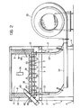
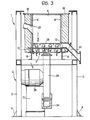
- a fluidized-bed calcining furnace generally indicated 1 is usable particularly for regenerating sands from casting boxes and cores.
- the furnace 1 is provided with a support structure 2 which, in the example illustrated, comprises four vertical pillars 3 each provided at its lower end with a support foot 4 intended to be anchored to the ground.
- the vertical pillars 3 support, at about half their height, a rectangular, horizontal frame formed by four beams 5 having, like the vertical pillars 3, a hollow square cross- section.
- Two opposite beams 5 in their turn support a base structure 7 by means of two cross pieces 6 constituted by two C-sections, the base 7 being illustrated on an enlarged scale in Figure 5.
- This Figure illustrates part of the base structure 7 in partially-sectioned perspective view.
- the base structure 7 Above the base structure 7 are fixed four perpendicular walls 8 which define the chamber 9 of the furnace. These walls are each provided externally with a ceramic-fibre coating wall 19.
- the base structure 7 includes a flat horizontal wall 10 intended to act as a base wall for a bed of refractory particles.
- the structure 7 further includes a-flat horizontal wall 11 disposed below the wall 10.
- FIG 5 the walls 10, 11 have been illustrated schematically as parts of a structure formed in a single piece.
- the wall 11 (see Figures 2, 3) is joined to the wall 10 by means of lengths of angle-iron 12 which, together with these walls, define a closed chamber 13.
- the lengths of angle-iron 12 at two opposite sides of the base structure 7 have apertures (one of which is indicated schematically in Figure 5 by the reference numeral 14) for allowing air into the chamber 13.
- the walls 10, 11 are provided with septa projecting into the chamber 13 to define a labyrinthine path for the air which is supplied to the chamber 13.
- the lower side of the wall 10 has four septa 15 (three of which are seen in Figure 5) terminating a short distance from the wall 11, which divide the chamber 13 into a central part and an annular peripheral chamber communicating with the two inlets 14. That part of the chamber 13 within the septa 15 is in its turn subdivided by two walls 16 projecting from the wall 11.
- Each wall 16 has a vertical section 17 adjacent a septum 15 and a horizontal section 18 adjacent the wall 10.
- the two horizontal sections 18 of the walls 16 have two facing edges 18a which terminate a short distance from each other.
- a vertical wall 19 projects from beneath the wall 10 into the zone separating the edges 18a.
- each wall 16 is further provided at its upper edge with a series of lugs 17a which extend up to the wall 10 so as to define a plurality of passages for communication between the annular peripheral chamber, indicated by 20, defined by the septa 15, and the space indicated by 21, between the wall 10 and the two walls 18.
- the base wall 10 is provided with a plurality of holes 22 within which are fixed tubular elements 23.
- each tubular element 23 has an upper end terminating slightly above the base wall 10 and a lower end communicating with the central part of the chamber 13.
- Each wall 18 has holes 24to allow the assembly of the tubular elements 23.
- each tubular element 23 Within each tubular element 23 extends a nozzle 25 for the discharge of combustible gas.
- Each nozzle 25 is constituted by a tube provided at its upper end, at a height substantially corresponding to that of the base wall 10, with discharge holes 26.
- Each nozzle 25 has, at its lower end, a screw-threaded body which is fixed in a corresponding hole 28 in the wall 11 by means of a nut 29.
- the lower ends 30 of the nozzles 25 communicate through flexible tubes with means for supplying a combustible gas.
- each tubular element 23 is surmounted by a cap element 31.
- the cap element 31 rests on the upper surface of the wall 10 and is provided with three equiangularly-spaced passages 32 (only one of which is visible in Figure 4) for communication between the interior of the tubular element 23 and the chamber 9 of the furnace.
- the two air-supply inlets 14 communicate with two pipes 33 (see Figure 2) which branch from a single delivery pipe 34 connected to the outlet of a fan 35 rotated by an electric motor 36 supported by a support structure 37.
- the air supplied by the fan 35 reaches the supply inlets 14 through the pipes 34 and 33. From the inlets 14the airflow passes successively into the annular chamber 20, into the space 21 and into the central part of the chamber 13 of the base structure 7. From here the air flow is supplied through the tubular elements 23 to the interior of the chamber 9 of the furnace.
- the combustible gas supplied to the nozzles 25 flows out of the discharge holes 26 of each nozzle 25 and mixes with the air at the moment of entry into the chamber 9 of the furnace.
- the cap elements 31 are arranged to facilitate the mixing of the combustible gas with the air.
- the lower surface of each cap element 31 may be provided with helical scoring so as to induce a certain degree of turbulence in the flow.
- the furnace further includes a flue structure (not illustrated) surmounting the chamber 9 for communication between the latter and the chimney.
- a duct for feeding material to be calcined to the furnace is formed in the flow structure.
- This material may, for example, be constituted by pieces of casting cores and boxes constituted by sand mixed with binding materials of various types.
- a metal mesh 38 for keeping the materials to be calcined, introduced into the chamber 9 separate from the bed of refractory particles with which the furnace is provided.
- the furnace is provided with an opening 39 for the insertion of a burner for igniting the mixture of air and combustible gas, a discharge duct 40, the height of which is adjustable, for discharging regenerated sand, and a duct 41 (see Figures 1, 3) for emptying out the bed of refractory particles.
- the discharge duct 40 is constituted by two tubular elements disposed coaxially one within the other and fixable in different positions with respect to each other by means of a transverse pin 42 insertable in any one of a plurality of holes 43.
- thermocouples 44 The furnace is finally provided with two thermocouples 44.
- the air and the combustible gas are supplied in the manner described above to the tubular elements 23 and to the nozzles 25 so that they mix together at their moment of entry into the chamber 9 of the furnace.
- the combustible gas burns within the bed of refractory particles at the same time causing fluidization.
- the free surface of the bed of refractory particles is located at the height of the upper end of the discharge opening 40.
- the material to be calcined is introduced into the chamber 9 of the furnace and as the sand is regenerated it is discharged through the duct 40 while the binding materials volatilize.
- the mixing of the combustible gas with the air is effected at the moment at which the combustible gas and the air are fed into the chamber of the furnace. This, on the one hand, achieves complete mixing and a uniform distribution of the combustible gas and the air within the bed and, at the same time, avoids the risk of the combustible gas burning before entering the bed.
- the particular conformation of the base structure 7 constrains the air to flow over the lower surface of the base plate 10 of the bed before it is fed into the chamber 9.
- cooling of the wall 10 is achieved simply and efficiently.
- each cap element 31 and the corresponding tubular element 23 may be formed in a single piece.
Landscapes
- Engineering & Computer Science (AREA)
- Chemical & Material Sciences (AREA)
- Combustion & Propulsion (AREA)
- Mechanical Engineering (AREA)
- General Engineering & Computer Science (AREA)
- Organic Chemistry (AREA)
- Chemical Kinetics & Catalysis (AREA)
- Dispersion Chemistry (AREA)
- Fluidized-Bed Combustion And Resonant Combustion (AREA)
- Crucibles And Fluidized-Bed Furnaces (AREA)
- Devices And Processes Conducted In The Presence Of Fluids And Solid Particles (AREA)
- Molds, Cores, And Manufacturing Methods Thereof (AREA)
Priority Applications (1)
| Application Number | Priority Date | Filing Date | Title |
|---|---|---|---|
| AT81830248T ATE12688T1 (de) | 1980-12-24 | 1981-12-22 | Wirbelschichtkalzinierofen, der insbesondere zur sandaufbereitung von sanden aus formkasten und - kernen benutzt wird. |
Applications Claiming Priority (2)
| Application Number | Priority Date | Filing Date | Title |
|---|---|---|---|
| IT68991/80A IT1188886B (it) | 1980-12-24 | 1980-12-24 | Forno di calcinazione a letto fluidizzato particolarmente per il recupero delle sabbie utilizzate in forme ed anime di fonderia |
| IT6899180 | 1980-12-24 |
Publications (2)
| Publication Number | Publication Date |
|---|---|
| EP0055230A1 EP0055230A1 (en) | 1982-06-30 |
| EP0055230B1 true EP0055230B1 (en) | 1985-04-10 |
Family
ID=11311104
Family Applications (1)
| Application Number | Title | Priority Date | Filing Date |
|---|---|---|---|
| EP81830248A Expired EP0055230B1 (en) | 1980-12-24 | 1981-12-22 | Fluidized bed calcining furnace, particularly for regenerating sands used in casting boxes and cores |
Country Status (7)
| Country | Link |
|---|---|
| US (1) | US4427375A (ja) |
| EP (1) | EP0055230B1 (ja) |
| JP (1) | JPS57134603A (ja) |
| AT (1) | ATE12688T1 (ja) |
| DE (1) | DE3169922D1 (ja) |
| ES (1) | ES262273Y (ja) |
| IT (1) | IT1188886B (ja) |
Families Citing this family (25)
| Publication number | Priority date | Publication date | Assignee | Title |
|---|---|---|---|---|
| IT1155658B (it) * | 1982-03-23 | 1987-01-28 | Fata Ind Spa | Sistema e metodo per il recupero delle sabbie contenute in forme ed anime di fonderia mediante calcinazione in un forno a letto fluidizzato |
| US4550669A (en) * | 1982-08-03 | 1985-11-05 | Sam Foresto | Burning apparatus with means for heating and cleaning polluted products of combustion |
| SE442242B (sv) * | 1983-03-02 | 1985-12-09 | Stal Laval Turbin Ab | Forfaringssett for rengoring av haloppningar och/eller dysor i hetvatten- eller angpannor med tva eller flera fluidiserade beddar |
| JPS6118312U (ja) * | 1984-06-30 | 1986-02-03 | バブコツク日立株式会社 | 流動層燃焼装置 |
| GB8629055D0 (en) * | 1986-12-04 | 1987-01-14 | Keirle T J | Fluidised bed furnaces |
| IT1237296B (it) * | 1989-11-28 | 1993-05-27 | Metodo per il recupero delle sabbie di fonderia esauste mediante arrostimento. | |
| US5271450A (en) * | 1990-05-11 | 1993-12-21 | Richards Engineering Limited | Thermal reclamation method |
| EP0612276B2 (en) † | 1992-08-13 | 2004-11-17 | Consolidated Engineering Company, Inc. | Heat treatment of metal castings and in-furnace sand reclamation |
| US5901775A (en) * | 1996-12-20 | 1999-05-11 | General Kinematics Corporation | Two-stage heat treating decoring and sand reclamation system |
| US5924473A (en) * | 1996-12-20 | 1999-07-20 | General Kinematics Corporation | Vibratory sand reclamation system |
| US6453982B1 (en) | 1996-12-20 | 2002-09-24 | General Kinematics Corporation | Sand cleaning apparatus |
| US6217317B1 (en) | 1998-12-15 | 2001-04-17 | Consolidated Engineering Company, Inc. | Combination conduction/convection furnace |
| US6336809B1 (en) | 1998-12-15 | 2002-01-08 | Consolidated Engineering Company, Inc. | Combination conduction/convection furnace |
| US7275582B2 (en) * | 1999-07-29 | 2007-10-02 | Consolidated Engineering Company, Inc. | Methods and apparatus for heat treatment and sand removal for castings |
| US6622775B2 (en) | 2000-05-10 | 2003-09-23 | Consolidated Engineering Company, Inc. | Method and apparatus for assisting removal of sand moldings from castings |
| KR100850601B1 (ko) * | 2001-02-02 | 2008-08-05 | 콘솔리데이티드 엔지니어링 캄파니, 인크. | 일체식 금속 처리 설비 |
| US7331374B2 (en) * | 2001-05-09 | 2008-02-19 | Consolidated Engineering Company, Inc. | Method and apparatus for assisting removal of sand moldings from castings |
| KR101211347B1 (ko) * | 2004-06-28 | 2012-12-11 | 콘솔리데이티드 엔지니어링 캄파니, 인크. | 주물로부터의 플래싱 및 방해물의 제거를 위한 방법 및장치 |
| US20060103059A1 (en) * | 2004-10-29 | 2006-05-18 | Crafton Scott P | High pressure heat treatment system |
| US20070289713A1 (en) * | 2006-06-15 | 2007-12-20 | Crafton Scott P | Methods and system for manufacturing castings utilizing an automated flexible manufacturing system |
| US7819071B2 (en) * | 2006-11-16 | 2010-10-26 | Seminatore Salvatore J | Nozzle system |
| EP2139628B1 (en) * | 2007-03-29 | 2013-02-27 | Consolidated Engineering Company, Inc. | Vertical heat treatment system |
| FI20086192A (fi) * | 2008-12-12 | 2010-06-13 | Foster Wheeler Energia Oy | Kiertoleijureaktori happipolttoon, menetelmä sellaisen reaktorin käyttämiseksi ja menetelmä kiertoleijureaktorin muuttamiseksi |
| US20120214109A1 (en) * | 2011-02-22 | 2012-08-23 | Alstom Technology Ltd | Fluidizing nozzle weld collar |
| CN110892196B (zh) * | 2017-04-28 | 2021-10-08 | 住友重机械福惠能源有限公司 | 流化气体喷嘴头以及具有多个流化气体喷嘴头的流化床反应器 |
Family Cites Families (4)
| Publication number | Priority date | Publication date | Assignee | Title |
|---|---|---|---|---|
| FR1327356A (fr) * | 1961-10-02 | 1963-05-17 | Gen Am Transport | Enceinte de fluidisation de solides |
| US3361539A (en) * | 1965-07-15 | 1968-01-02 | Pyzel Robert | Fluidized solids reactor |
| DE1813286A1 (de) * | 1968-12-07 | 1970-07-16 | Metallgesellschaft Ag | Gaszufuehrung fuer Wirbelschichtreaktoren |
| SU474665A1 (ru) * | 1973-06-13 | 1975-06-25 | Государственный Всесоюзный Научно-Исследовательский Институт Строительных Материалов И Конструкций | Шахтна печь кип щего сло |
-
1980
- 1980-12-24 IT IT68991/80A patent/IT1188886B/it active
-
1981
- 1981-12-17 US US06/332,101 patent/US4427375A/en not_active Expired - Fee Related
- 1981-12-22 EP EP81830248A patent/EP0055230B1/en not_active Expired
- 1981-12-22 DE DE8181830248T patent/DE3169922D1/de not_active Expired
- 1981-12-22 AT AT81830248T patent/ATE12688T1/de active
- 1981-12-23 ES ES1981262273U patent/ES262273Y/es not_active Expired
- 1981-12-24 JP JP56208269A patent/JPS57134603A/ja active Pending
Also Published As
| Publication number | Publication date |
|---|---|
| JPS57134603A (en) | 1982-08-19 |
| US4427375A (en) | 1984-01-24 |
| ES262273Y (es) | 1983-01-01 |
| IT8068991A0 (it) | 1980-12-24 |
| ATE12688T1 (de) | 1985-04-15 |
| DE3169922D1 (en) | 1985-05-15 |
| EP0055230A1 (en) | 1982-06-30 |
| IT1188886B (it) | 1988-01-28 |
| ES262273U (es) | 1982-06-16 |
Similar Documents
| Publication | Publication Date | Title |
|---|---|---|
| EP0055230B1 (en) | Fluidized bed calcining furnace, particularly for regenerating sands used in casting boxes and cores | |
| US4528917A (en) | Solid fuel burner | |
| CA1094802A (en) | Fluidised bed | |
| US4628831A (en) | Hearth and process for fluidized-bed treatment of a fuel | |
| CA2087399C (en) | Wet-base, down-fired water heater | |
| US3804079A (en) | Melting kettle and apparatus and method for eliminating objectionable emissions therefrom | |
| US4454826A (en) | Vertical flow incinerator having regenerative heat exchange | |
| WO2017206430A1 (zh) | 具有均匀配风装置的循环流化床燃烧系统 | |
| US4574743A (en) | Heat generator for heating a fluid by heat exchange through a fluidized bed and a process for implementing same | |
| US4621610A (en) | Solid fuel heating apparatus | |
| US3813209A (en) | Preheating of metal scrap | |
| EP0349764B1 (de) | Wirbelschichtfeuerung | |
| EP0223270A1 (en) | Incinerator for the high speed combustion of waste products | |
| US4281983A (en) | Premix burner system for low BTU gas fuel | |
| US4422388A (en) | Wood and other solid register burner | |
| CA1273004A (en) | Gas and solid particulate material heat exchanger | |
| US3669429A (en) | Tobacco curing apparatus | |
| US5363836A (en) | Furnace with supplementary heat exchange means | |
| US5771819A (en) | Incinerating furnace | |
| US3813214A (en) | Drying oven for lead battery plates | |
| US4343247A (en) | Fluidized bed combustion method and apparatus | |
| US4344372A (en) | Fluidized bed combustion device | |
| US4412814A (en) | Apparatus and method for operating a brick kiln | |
| US3202405A (en) | Vertical shaft kiln and method of operation thereof | |
| CA1096166A (en) | Ignition hood with swirl combustion chamber |
Legal Events
| Date | Code | Title | Description |
|---|---|---|---|
| PUAI | Public reference made under article 153(3) epc to a published international application that has entered the european phase |
Free format text: ORIGINAL CODE: 0009012 |
|
| AK | Designated contracting states |
Designated state(s): AT BE CH DE FR GB IT LU NL SE |
|
| 17P | Request for examination filed |
Effective date: 19821001 |
|
| ITF | It: translation for a ep patent filed |
Owner name: JACOBACCI & PERANI S.P.A. |
|
| GRAA | (expected) grant |
Free format text: ORIGINAL CODE: 0009210 |
|
| AK | Designated contracting states |
Designated state(s): AT BE CH DE FR GB IT LI LU NL SE |
|
| PG25 | Lapsed in a contracting state [announced via postgrant information from national office to epo] |
Ref country code: AT Effective date: 19850410 |
|
| REF | Corresponds to: |
Ref document number: 12688 Country of ref document: AT Date of ref document: 19850415 Kind code of ref document: T |
|
| PG25 | Lapsed in a contracting state [announced via postgrant information from national office to epo] |
Ref country code: SE Effective date: 19850430 |
|
| REF | Corresponds to: |
Ref document number: 3169922 Country of ref document: DE Date of ref document: 19850515 |
|
| ET | Fr: translation filed | ||
| PG25 | Lapsed in a contracting state [announced via postgrant information from national office to epo] |
Ref country code: LU Free format text: LAPSE BECAUSE OF NON-PAYMENT OF DUE FEES Effective date: 19851231 |
|
| PLBE | No opposition filed within time limit |
Free format text: ORIGINAL CODE: 0009261 |
|
| STAA | Information on the status of an ep patent application or granted ep patent |
Free format text: STATUS: NO OPPOSITION FILED WITHIN TIME LIMIT |
|
| 26N | No opposition filed | ||
| PGFP | Annual fee paid to national office [announced via postgrant information from national office to epo] |
Ref country code: CH Payment date: 19921116 Year of fee payment: 12 |
|
| PGFP | Annual fee paid to national office [announced via postgrant information from national office to epo] |
Ref country code: GB Payment date: 19921119 Year of fee payment: 12 |
|
| PGFP | Annual fee paid to national office [announced via postgrant information from national office to epo] |
Ref country code: DE Payment date: 19921125 Year of fee payment: 12 |
|
| PGFP | Annual fee paid to national office [announced via postgrant information from national office to epo] |
Ref country code: BE Payment date: 19921126 Year of fee payment: 12 |
|
| PGFP | Annual fee paid to national office [announced via postgrant information from national office to epo] |
Ref country code: FR Payment date: 19921230 Year of fee payment: 12 |
|
| ITTA | It: last paid annual fee | ||
| PGFP | Annual fee paid to national office [announced via postgrant information from national office to epo] |
Ref country code: NL Payment date: 19921231 Year of fee payment: 12 |
|
| PG25 | Lapsed in a contracting state [announced via postgrant information from national office to epo] |
Ref country code: GB Effective date: 19931222 |
|
| PG25 | Lapsed in a contracting state [announced via postgrant information from national office to epo] |
Ref country code: LI Effective date: 19931231 Ref country code: CH Effective date: 19931231 Ref country code: BE Effective date: 19931231 |
|
| BERE | Be: lapsed |
Owner name: FATA EUROPEAN GROUP S.P.A. Effective date: 19931231 |
|
| PG25 | Lapsed in a contracting state [announced via postgrant information from national office to epo] |
Ref country code: NL Effective date: 19940701 |
|
| NLV4 | Nl: lapsed or anulled due to non-payment of the annual fee | ||
| GBPC | Gb: european patent ceased through non-payment of renewal fee |
Effective date: 19931222 |
|
| PG25 | Lapsed in a contracting state [announced via postgrant information from national office to epo] |
Ref country code: FR Effective date: 19940831 |
|
| REG | Reference to a national code |
Ref country code: CH Ref legal event code: PL |
|
| PG25 | Lapsed in a contracting state [announced via postgrant information from national office to epo] |
Ref country code: DE Effective date: 19940901 |
|
| REG | Reference to a national code |
Ref country code: FR Ref legal event code: ST |