EP0055185B1 - Device for absorbing the shocks between a load and a floating support at the moment the load is taken up - Google Patents
Device for absorbing the shocks between a load and a floating support at the moment the load is taken up Download PDFInfo
- Publication number
- EP0055185B1 EP0055185B1 EP81402049A EP81402049A EP0055185B1 EP 0055185 B1 EP0055185 B1 EP 0055185B1 EP 81402049 A EP81402049 A EP 81402049A EP 81402049 A EP81402049 A EP 81402049A EP 0055185 B1 EP0055185 B1 EP 0055185B1
- Authority
- EP
- European Patent Office
- Prior art keywords
- load
- floating support
- support
- absorbing
- shocks
- Prior art date
- Legal status (The legal status is an assumption and is not a legal conclusion. Google has not performed a legal analysis and makes no representation as to the accuracy of the status listed.)
- Expired
Links
Images
Classifications
-
- E—FIXED CONSTRUCTIONS
- E02—HYDRAULIC ENGINEERING; FOUNDATIONS; SOIL SHIFTING
- E02B—HYDRAULIC ENGINEERING
- E02B17/00—Artificial islands mounted on piles or like supports, e.g. platforms on raisable legs or offshore constructions; Construction methods therefor
- E02B17/02—Artificial islands mounted on piles or like supports, e.g. platforms on raisable legs or offshore constructions; Construction methods therefor placed by lowering the supporting construction to the bottom, e.g. with subsequent fixing thereto
- E02B17/021—Artificial islands mounted on piles or like supports, e.g. platforms on raisable legs or offshore constructions; Construction methods therefor placed by lowering the supporting construction to the bottom, e.g. with subsequent fixing thereto with relative movement between supporting construction and platform
- E02B17/024—Artificial islands mounted on piles or like supports, e.g. platforms on raisable legs or offshore constructions; Construction methods therefor placed by lowering the supporting construction to the bottom, e.g. with subsequent fixing thereto with relative movement between supporting construction and platform shock absorbing means for the supporting construction
-
- B—PERFORMING OPERATIONS; TRANSPORTING
- B63—SHIPS OR OTHER WATERBORNE VESSELS; RELATED EQUIPMENT
- B63B—SHIPS OR OTHER WATERBORNE VESSELS; EQUIPMENT FOR SHIPPING
- B63B35/00—Vessels or similar floating structures specially adapted for specific purposes and not otherwise provided for
- B63B35/003—Vessels or similar floating structures specially adapted for specific purposes and not otherwise provided for for transporting very large loads, e.g. offshore structure modules
-
- B—PERFORMING OPERATIONS; TRANSPORTING
- B66—HOISTING; LIFTING; HAULING
- B66F—HOISTING, LIFTING, HAULING OR PUSHING, NOT OTHERWISE PROVIDED FOR, e.g. DEVICES WHICH APPLY A LIFTING OR PUSHING FORCE DIRECTLY TO THE SURFACE OF A LOAD
- B66F19/00—Hoisting, lifting, hauling or pushing, not otherwise provided for
Definitions
- the present invention relates to a device for absorbing shocks between a load and a floating support at the time of removal of the load from the floating support, said support comprising at least one casing on which the load rests and with which a damping member is associated.
- a device for absorbing shocks between a load and a floating support at the time of removal of the load from the floating support, said support comprising at least one casing on which the load rests and with which a damping member is associated.
- Such a device is known, for example, from NL-A-7 801 724.
- the present invention aims to overcome these drawbacks and relates to a device for absorbing shocks between a load and a floating support comprising the characteristics described in the claim.
- Fig. 4 is a section on IV-IV of FIG. 1 in enlarged view.
- Fig. 5 is a section V-V of FIG. 4.
- Fig. 6 gives a general presentation of a particular application of the invention in the particularly interesting case of the removal of a marine platform from its transport barge and its installation on a fixed structure previously installed.
- the circled part A of this figure being detailed in the previous figures.
- the device according to the invention firstly comprises externally a cabin 10 integral with a floating support 70 of a load 1.
- the casing 10 has on two of its faces massive parts 30. Inside this casing is disposed a jacket 11 comprising a cylindrical side wall 12 and a bottom 13 at the upper part of the side wall. At the bottom of the jacket 11 is placed a shock absorber 14, for example an elastomer block. Under this shock absorber, a wedge 15 with an inclined lower face 16 is placed. This wedge is placed at the bottom of a cylindrical box 17 which can slide vertically in the jacket 11 by more or less compressing the damper 14.
- a corner 18 with an inclined upper face 60 cooperates with the wedge 15 and passes through the cabin 10, the jacket 11 and the box 17 by slots 19 made in the solid parts 30 of the cabin 10, 20 made in the jacket 11 and 21 practiced in the box 17.
- the corner 18 rests on the bottom 50 of the slots 19 made in the solid parts 30; pulling the wedge 18 in the direction of the arrow F causes the wedge 15 to rise and, in the absence of high weight on the top of the bottom 13 of the liner 11, that of the damping member 14 and the shirt 11 as seen in fig. 2.
- the tensile force in the direction of arrow F can be achieved in any way: stretched nylon, weight suspended on the edges of the floating support with return pulley ...
- the stroke of the corner 18 is limited by a stop 61.
- the wedge 18 is in the position where it is shown in FIG. 1.
- the wedge 15 and the jacket 11 are in the low position, the assembly is returned to the cabin 10 and the load 1 rests on the casing (FIGS. 1 and 4).
- the jacket 11 is relieved of its weight and under the force exerted on the wedge 18 in the direction of the arrow F, the corner is moved which causes the rise of the wedge 5 and with it, that of the armotor 14 and the jacket 11.
- the floating support 70 rises under the effect of a wave top, and the load has not yet been sufficiently high, the weight of the latter then compresses the damper 14 such that see it in fig. 3.
- the device makes it possible to automatically insert, and only when the load is removed, a damping device between the load and its floating support.
- the angle of the corner 18 is calculated taking into account the coefficient of friction and the force F so that the movement is irreversible whatever the load on the jacket 11.
- Fig. 6 shows a particularly interesting application of the discharge of a marine platform from a transport barge and its installation on a fixed structure previously installed.
- the figure shows a platform 1 supported by a floating barge 2.
- the platform must be installed on a support structure comprising feet 3 which emerge and which include centering cones 40.
- the platform 2 is equipped with batteries 4 mobile thanks to a lifting system 5.
- the batteries have inside a damping device comprising a pin 6 bearing against a shock absorber 7 made of elastomer for example.
- a jack 8 associated with removable wedges 9 allows the final docking of the stacks 4 against the feet 3 and makes it possible to carry out the welds between the stacks and the feet while the load of the platform does not yet or entirely rest on the top of the feet but only on the centering cones 40 via the pin 6, the shock absorber 7 and the jack 8.
- This device is described in detail in the application of EP-A-0 054 914 filed by the Applicant company and entitled "Device for the establishment of a marine platform on the support structure".
- the device according to the invention A has been placed, described in detail in the preceding figures.
- the platform 1 is raised from the barge 2, by means of the machinery 5 which first of all lowers the stack 4 until the pinoche 6 makes contact with the centering cone 4, the effects of the swell being damped by the damper 7; at the same time, the shocks between the barge 2 and the platform 1, consecutive to a crest of swell succeeding a hollow during which the platform taking support on the feet 3 took off from the barge 2, are absorbed by to devices according to the invention and described above.
Landscapes
- Engineering & Computer Science (AREA)
- Mechanical Engineering (AREA)
- Structural Engineering (AREA)
- General Engineering & Computer Science (AREA)
- Combustion & Propulsion (AREA)
- Ocean & Marine Engineering (AREA)
- Chemical & Material Sciences (AREA)
- Civil Engineering (AREA)
- Transportation (AREA)
- Life Sciences & Earth Sciences (AREA)
- Geology (AREA)
- Vibration Prevention Devices (AREA)
- Vibration Dampers (AREA)
- Carriers, Traveling Bodies, And Overhead Traveling Cranes (AREA)
Description
La présente invention concerne un dispositif pour amortir les chocs entre une charge et un support flottant au moment de l'enlèvement de la charge du support flottant, ledit support comprenant au moins un carlingage sur lequel repose la charge et auquel un organe amortisseur est associé. Un tel dispositif est connu, par exemple, par le NL-A-7 801 724.The present invention relates to a device for absorbing shocks between a load and a floating support at the time of removal of the load from the floating support, said support comprising at least one casing on which the load rests and with which a damping member is associated. Such a device is known, for example, from NL-A-7 801 724.
En effet, en présence de houle, pour des charges très importantes où la vitesse d'enlèvement ne peut pas être très rapide, on passe au moment de l'enlèvement par des phases critiques où la charge décolle de son support au moment d'un creux de houle et reprend contact avec lui au moment d'une crête. Pour éviter d'endommager le matériel, charge et support, il est donc nécessaire de prévoir un dispositif d'armo- tissement entre la charge et le support flottant.Indeed, in the presence of swell, for very large loads where the removal speed cannot be very fast, we pass at the time of removal through critical phases where the load takes off from its support at the time of a swells and resumes contact with him at the time of a crest. To avoid damaging the equipment, load and support, it is therefore necessary to provide a damping device between the load and the floating support.
La nécessité d'une liaison rigide, non élastique, donc fer sur fer sans amortisseur pendant le transport a conduit à placer des systèmes amortisseurs au droit des points de supportage: les carlingages, mais juste seulement avant le déchargement. Une solution connue consiste donc à élever la charge à partir du support flottant de manière à pouvoir intercaler des systèmes amortisseurs. Cependant cette solution présente des inconvénients:
- En effet elle entraîne une phase, même si le déchargement est effectué immédiatement après, au cours de laquelle la charge repose élastiquement sur un support flottant, il peut donc y avoir des risques de résonance de la charge avec la houle. Il est nécessaire d'autre part de lever la charge à partir du support flottant pour ne pas retomber dans la difficulté que l'on veut résoudre, ce qui nécessite des moyens de levage importants, des points de supportage supplémentaires ...
- Indeed it causes a phase, even if the unloading is carried out immediately after, during which the load rests elastically on a floating support, there can therefore be risks of resonance of the load with the swell. It is also necessary to lift the load from the floating support so as not to fall back into the difficulty that we want to solve, which requires significant lifting means, additional support points ...
La présente invention a pour but de pallier ces inconvénients et a pour objet un dispositif pour amortir les chocs entre une charge et un support flottant comprenant les caractéristiques décrit dans la revendication.The present invention aims to overcome these drawbacks and relates to a device for absorbing shocks between a load and a floating support comprising the characteristics described in the claim.
L'invention sera bien comprise à la lumière de la description d'un exemple de réalisation du dispositif de l'invention, faite ce-après en regard du dessin annexé dans lequel:
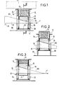
- Les fig. 1, 2 et 3 montrent le dispositif selon l'invention dans différentes positions.
- Figs. 1, 2 and 3 show the device according to the invention in different positions.
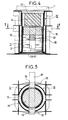
La fig. 4 est une coupe selon IV-IV de la fig. 1 en vue agrandie.Fig. 4 is a section on IV-IV of FIG. 1 in enlarged view.
La fig. 5 est une coupe V-V de la fig. 4.Fig. 5 is a section V-V of FIG. 4.
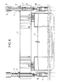
La fig. 6 donne une présentation générale d'une application particulière de l'invention dans le cas particulièrement intéressant de l'enlèvement d'une plate-forme marine de sa barge de transport et de sa pose sur une structure fixe préalablement installée. La partie entourée A de cette figure étant détaillée dans les figures précédentes.Fig. 6 gives a general presentation of a particular application of the invention in the particularly interesting case of the removal of a marine platform from its transport barge and its installation on a fixed structure previously installed. The circled part A of this figure being detailed in the previous figures.
En se référant aux fig. 1, 4 et 5, le dispositif selon l'invention comporte d'abord extérieurement un carlingage 10 solidaire d'un support flottant 70 d'une charge 1.Referring to fig. 1, 4 and 5, the device according to the invention firstly comprises externally a
Le carlingage 10 possède sur deux de ses faces des pièces massives 30. A l'intérieur de ce carlingage est disposée une chemise 11 comportant une paroi latérale cylindrique 12 et un fond 13 à la partie supérieure de la paroi latérale. Au fond de la chemise 11 est placé un amortisseur de chocs 14 par exemple un bloc en élastomère. Sous cet amortisseur, est placée une cale 15 à face inférieure 16 inclinée. Cette cale est placée au fond d'une boite cylindrique 17 pouvant coulisser verticalement dans la chemise 11 en comprimant plus ou moins l'amortisseur 14.The
Un coin 18 à face supérieure 60 inclinée coopère avec la cale 15 et traverse la carlingage 10, la chemise 11 et la boîte 17 par des fentes 19 pratiquées dans les pièces massives 30 du carlingage 10, 20 pratiquées dans la chemise 11 et 21 pratiquées dans la boîte 17. Le coin 18 repose sur le fond 50 des fentes 19 pratiquées dans les pièces massives 30; la traction du coin 18 dans le sens de la flèche F provoque la montée de la cale 15 et, en l'absence de poids élevé sur le sommet du fond 13 de la chemise 11, celle également de l'organe amortisseur 14 et de la chemise 11 comme on le voit sur la fig. 2.A
L'effort de traction dans le sens de la flèche F peut être réalisé de toutes les façons: nylon tendu, poids suspendu sur les bords du support flottant avec poulie de renvoie ...The tensile force in the direction of arrow F can be achieved in any way: stretched nylon, weight suspended on the edges of the floating support with return pulley ...
La course du coin 18 est limitée par une butée 61.The stroke of the
Le fonctionnement du dispositif est le suivant, au cours du transport, le coin 18 se trouve dans la position où il est représenté sur la fig. 1. Dans cette position, la cale 15 et la chemise 11 se trouvent en position basse, l'ensemble est rentré dans le carlingage 10 et la charge 1 repose sur le cartingage (fig. 1 et 4). Au moment de l'enlèvement de la charge, lorsque celle-ci décolle du support flottant 70, par exemple dans un creux de vague, la chemise 11 est soulagée de son poids et sous l'effort exercé sur le coin 18 dans le sens de la flèche F, le coin est déplacé ce qui provoque la montée de la cale 5 et avec elle, celle de l'armotisseur 14 et de la chemise 11. On obtient alors la position représentée sur la fig. 2. Lorsque au contraire le support flottant 70 remonte sous l'effet d'un haut de vague, et que la charge n'ait pas encore été suffisamment élevée, le poids de celle-ci comprime alors l'amortisseur 14 tel qu'on le voit sur la fig. 3.The operation of the device is as follows, during transport, the
Dans ces deux fig. 2 et 3, le charge 1 n'a pas été représentée mais bien entendu, elle respose sur le dispositif comme dans les fig. 1 et 4.In these two figs. 2 and 3, the load 1 has not been shown but of course, it is exposed on the device as in FIGS. 1 and 4.
On voit donc que le dispositif permet d'intercaler automatiquement et seulement au moment de l'enlèvement de la charge, un dispositif amortisseur entre la charge et son support flottant.It can therefore be seen that the device makes it possible to automatically insert, and only when the load is removed, a damping device between the load and its floating support.
Il n'y a donc pas de période d'instabilité comme dans les dispositifs connus puisque l'amortisseur n'apparaît que durant la phase même de l'enlèvement de la charge. On supprime également tout dispositif annexe de levage de la charge sur le support flottant.There is therefore no period of instability as in the known devices since the damper only appears during the phase even from the removal of the load. It also removes any additional device for lifting the load on the floating support.
Bien entendu l'angle du coin 18 est calculé compte tenu du coefficient de frottement et de la force F pour que le mouvement soit irréversible quelque soit la charge sur la chemise 11.Of course, the angle of the
La fig. 6 représente une application particulièrement intéressante de la décharge d'une plate-forme marine d'une barge de transport et sa pose sur une structure fixe préalablement installée.Fig. 6 shows a particularly interesting application of the discharge of a marine platform from a transport barge and its installation on a fixed structure previously installed.
La figure montre une plate-forme 1 supportée par une barge flottante 2. La plate-forme doit être installée sur une structure support comportant des pieds 3 qui émergent et qui comprennent des cônes de centrage 40. La plate-forme 2 est équipée de piles 4 mobiles grâce à un système de levage 5. Les piles comportent en leur intérieur un dispositif d'amortissement comportant une pinoche 6 prenant appui contre un amortisseur 7 en élastomère par exemple. Un vérin 8 associé à des cales amovibles 9 permet l'accostage final des piles 4 contre les pieds 3 et permet de réaliser les soudures entre piles et pieds alors que la charge de la plate-forme ne repose pas encore ou pas en totalité sur le sommet des pieds mais seulement sur les cônes de centrage 40 par l'intermédiaire de la pinoche 6, de l'amortisseur 7 et du vérin 8. Ce dispositif est décrit en détail dans la demande de EP-A-0 054 914 déposé par la Société demanderesse et ayant pour titre »Dispositif pour la mise en place d'une plate-forme marine sur la structure support«.The figure shows a platform 1 supported by a floating barge 2. The platform must be installed on a support structure comprising feet 3 which emerge and which include centering
Entre la plate-forme 1 et la barge de transport 2 on a placé le dispositif selon l'invention A décrit en détail dans les figures précédentes. Ainsi, dans cette application la plate-forme 1 est soulevée de la barge 2, par l'intermédiaire de la machinerie 5 qui fait d'abord descendre la pile 4 jusqu'à la prise de contact de la pinoche 6 avec le cône de centrage 4, les effets de la houle étant amortis par l'amortisseur 7; en même temps, les chocs entre la barge 2 et la plate-forme 1, consécutifs à une crête de houle succédant à un creux au cours duquel la plate-forme prenant appui sur les pieds 3 a décollé de la barge 2, sont amortis grâce aux dispositifs à suivant l'invention et décrits plus haut.Between the platform 1 and the transport barge 2, the device according to the invention A has been placed, described in detail in the preceding figures. Thus, in this application the platform 1 is raised from the barge 2, by means of the
Claims (1)
- A device for absorbing the shocks between a load (1) and a floating support (70) at the moment the load is taken away from said support, said support comprising at least one prop structure (10) on which the load rests and to which a shock-absorbing element (14) is associated, characterized in that the shock-absorbing element (14) is disposed within said prop structure (10) and cooperates with a wedge (18) situated below said element and submitted to a horizontal traction force (F) so as to push automatically and irreversibly the shock-absorbing element between the load and its prop point on the floating support as soon as the load is lifted from the floating support.
Applications Claiming Priority (2)
| Application Number | Priority Date | Filing Date | Title |
|---|---|---|---|
| FR8027348A FR2496624A1 (en) | 1980-12-23 | 1980-12-23 | DEVICE FOR SHOCK ABSORBING BETWEEN A LOAD AND A FLOATING SUPPORT AT THE TIME OF REMOVAL OF THE LOAD |
| FR8027348 | 1980-12-23 |
Publications (2)
| Publication Number | Publication Date |
|---|---|
| EP0055185A1 EP0055185A1 (en) | 1982-06-30 |
| EP0055185B1 true EP0055185B1 (en) | 1984-08-29 |
Family
ID=9249416
Family Applications (1)
| Application Number | Title | Priority Date | Filing Date |
|---|---|---|---|
| EP81402049A Expired EP0055185B1 (en) | 1980-12-23 | 1981-12-22 | Device for absorbing the shocks between a load and a floating support at the moment the load is taken up |
Country Status (7)
| Country | Link |
|---|---|
| US (1) | US4408930A (en) |
| EP (1) | EP0055185B1 (en) |
| JP (1) | JPS57502009A (en) |
| DE (1) | DE3165799D1 (en) |
| FR (1) | FR2496624A1 (en) |
| NO (1) | NO152803C (en) |
| WO (1) | WO1982002220A1 (en) |
Families Citing this family (8)
| Publication number | Priority date | Publication date | Assignee | Title |
|---|---|---|---|---|
| GB2174648B (en) * | 1985-04-29 | 1988-10-12 | Heerema Engineering | Installation and removal vessel |
| US4655641A (en) * | 1985-10-18 | 1987-04-07 | Exxon Production Research Co. | Apparatus for aligning a platform deck and jacket |
| GB2239280B (en) * | 1989-12-06 | 1993-06-23 | Marathon Oil Co | Motion absorbing docking assembly |
| US5035395A (en) * | 1989-12-15 | 1991-07-30 | Bigge Crane And Rigging Co. | Support cradle for load equalization |
| US5553977A (en) * | 1994-12-16 | 1996-09-10 | Northrop Grumman Corporation | Off-shore platform construction, and method for transferring loads |
| DE29716792U1 (en) * | 1997-09-18 | 1997-11-13 | Schrepfer Air Loc Ag | Device for increasing the height adjustment range in a leveling shoe and leveling shoe provided therewith |
| NL2014042B1 (en) * | 2014-12-23 | 2016-10-12 | Heerema Marine Contractors Nl | Support device configured to be positioned on a lifting vessel in order to lift a topside from its support structure. |
| CN107381448A (en) * | 2017-06-08 | 2017-11-24 | 安徽机电职业技术学院 | A kind of voussoir raises formula jacking machinery |
Family Cites Families (17)
| Publication number | Priority date | Publication date | Assignee | Title |
|---|---|---|---|---|
| US2734739A (en) * | 1956-02-14 | Messina | ||
| US2262443A (en) * | 1940-06-29 | 1941-11-11 | Mathews Conveyer Co | Roller conveyer |
| US2817212A (en) * | 1954-10-25 | 1957-12-24 | Frederick Snare Corp | Method for erecting and dismantling support structure |
| US2881590A (en) * | 1955-12-16 | 1959-04-14 | Shell Oil Co | Loading apparatus |
| FR1214760A (en) * | 1958-02-03 | 1960-04-12 | Bataafsche Petroleum | Method for removing a platform from a support device placed in water or for setting it there and installation for performing this method |
| NL142746B (en) * | 1965-01-08 | 1974-07-15 | Gusto Fa Nv | DRILLING ISLAND OR SIMILAR PLATFORM. |
| US3376031A (en) * | 1965-10-19 | 1968-04-02 | Destech Labs Inc | Shock absorber |
| US3606295A (en) * | 1968-11-12 | 1971-09-20 | Unilan Ag | Shock absorber |
| US3871527A (en) * | 1973-04-04 | 1975-03-18 | Westinghouse Electric Corp | Ram tensioning device |
| NL7400716A (en) * | 1974-01-18 | 1975-07-22 | Hattum & Blankevoort Bv | Shock absorber for off-shore oil well operating platform - with legs able to be lowered to the seabed |
| DE2432898C2 (en) * | 1974-07-09 | 1976-07-29 | Kober Ag | SLIDING TILT BEARING FOR BRIDGES OD. SIMILAR STRUCTURES |
| US3986368A (en) * | 1975-05-27 | 1976-10-19 | Levingston Shipbuilding Company | Load equalizing and shock absorber system for off-shore drilling rigs |
| FR2383118A1 (en) * | 1977-03-10 | 1978-10-06 | Metalliques Entrepr Cie Fse | Assembly for installation of offshore oil drilling rig - has screw jacks enabling positioning of piles relative to platform and includes shock absorbers |
| NL7801724A (en) * | 1978-02-15 | 1979-08-17 | Kens B V | Vessel for raising and conveying offshore platform - uses hydraulic jacks coupled to pressure accumulator to absorb shocks caused by impact |
| NL7804479A (en) * | 1978-04-26 | 1979-10-30 | Verolme Maschf Engineering Com | Mobile offshore drilling platform with retractable piles - has cushions between pile climbing mechanism and pontoon pressurised when pontoon is floating |
| US4195950A (en) * | 1978-08-17 | 1980-04-01 | Goldman Jerome L | Shock absorbing structure and method for off shore jack-up rigs |
| JPS59165701U (en) * | 1983-04-21 | 1984-11-07 | パイオニア株式会社 | cold rolling mill |
-
1980
- 1980-12-23 FR FR8027348A patent/FR2496624A1/en active Granted
-
1981
- 1981-08-24 US US06/295,453 patent/US4408930A/en not_active Expired - Fee Related
- 1981-12-22 DE DE8181402049T patent/DE3165799D1/en not_active Expired
- 1981-12-22 WO PCT/FR1981/000166 patent/WO1982002220A1/en unknown
- 1981-12-22 EP EP81402049A patent/EP0055185B1/en not_active Expired
- 1981-12-22 JP JP57500219A patent/JPS57502009A/ja active Pending
- 1981-12-22 NO NO814408A patent/NO152803C/en unknown
Also Published As
| Publication number | Publication date |
|---|---|
| FR2496624B1 (en) | 1985-05-10 |
| JPS57502009A (en) | 1982-11-11 |
| NO152803C (en) | 1985-11-20 |
| DE3165799D1 (en) | 1984-10-04 |
| WO1982002220A1 (en) | 1982-07-08 |
| US4408930A (en) | 1983-10-11 |
| FR2496624A1 (en) | 1982-06-25 |
| NO814408L (en) | 1982-06-24 |
| NO152803B (en) | 1985-08-12 |
| EP0055185A1 (en) | 1982-06-30 |
Similar Documents
| Publication | Publication Date | Title |
|---|---|---|
| EP0054914B1 (en) | Device for setting up an offshore platform on a supporting structure | |
| EP0055185B1 (en) | Device for absorbing the shocks between a load and a floating support at the moment the load is taken up | |
| EP1701602B1 (en) | System and method for packaging a rack for computer, rack for computer and transport pallet for this rack | |
| EP0807081A1 (en) | Load separator for a dynamic storage lane | |
| EP0065695B1 (en) | Leg of an offshore platform and method of placing it | |
| CA1074818A (en) | Marine flood transfer process and method | |
| EP2556330B1 (en) | Device for setting off an avalanche | |
| EP0145525B1 (en) | Device for handling articles | |
| FR2829121A1 (en) | Underground storage unit for domestic waste bins comprises lined pit with cage linked to counterweighted pulley and cable system | |
| EP0041901B1 (en) | Gripping device for containers or similar objects comprising level detectors | |
| FR2664561A1 (en) | HELICOPTER. | |
| FR2677750A1 (en) | TRAPPED WIRE MINE. | |
| CH675402A5 (en) | ||
| FR2492007A2 (en) | Vane for vertical axis wind generator - has sliding inner section to reduce blade area in strong winds | |
| FR2540218A1 (en) | DISCHARGE VALVE WITH PRESSURE DIFFERENCE CONTROL | |
| FR2729724A1 (en) | Spacecraft component bearing resisting launch vibration | |
| EP3342708A1 (en) | Device for releasing a load attached below an aircraft comprising two connecting rod assemblies mounted in parallel | |
| EP0449842A1 (en) | Polyvalent device for fast lifting of glass plates. | |
| FR2464209A1 (en) | Pallet bag loader conveyor - has conveyor for pallet and vibrating table to level bag layers on pallet | |
| FR2568862A1 (en) | Load lifting appts. for building sites | |
| FR2548647A1 (en) | Device for automatic handling of loads or of various articles | |
| FR2829120A1 (en) | Underground storage unit for domestic waste bins comprises lined pit with cage linked to counterweighted pulley and cable system | |
| EP3138104B1 (en) | Device for opening and closing an opening in the bottom of a pool intended for containing irradiated fuel | |
| FR1459994A (en) | Improvements to floating containers, especially for garbage collection in port basins | |
| FR2516112A1 (en) | Offshore drilling rig placement method - uses adjustable-ballast barge with computer controlling foot length to compensate swell and give controlled deceleration during descent |
Legal Events
| Date | Code | Title | Description |
|---|---|---|---|
| PUAI | Public reference made under article 153(3) epc to a published international application that has entered the european phase |
Free format text: ORIGINAL CODE: 0009012 |
|
| AK | Designated contracting states |
Designated state(s): DE FR GB IT NL |
|
| 17P | Request for examination filed |
Effective date: 19821130 |
|
| RAP1 | Party data changed (applicant data changed or rights of an application transferred) |
Owner name: ALSTHOM-ATLANTIQUE SOCIETE ANONYME DITE: |
|
| ITF | It: translation for a ep patent filed |
Owner name: JACOBACCI & PERANI S.P.A. |
|
| GRAA | (expected) grant |
Free format text: ORIGINAL CODE: 0009210 |
|
| PGFP | Annual fee paid to national office [announced via postgrant information from national office to epo] |
Ref country code: FR Payment date: 19840810 Year of fee payment: 4 |
|
| PGFP | Annual fee paid to national office [announced via postgrant information from national office to epo] |
Ref country code: DE Payment date: 19840823 Year of fee payment: 4 |
|
| AK | Designated contracting states |
Designated state(s): DE FR GB IT NL |
|
| REF | Corresponds to: |
Ref document number: 3165799 Country of ref document: DE Date of ref document: 19841004 |
|
| PLBE | No opposition filed within time limit |
Free format text: ORIGINAL CODE: 0009261 |
|
| STAA | Information on the status of an ep patent application or granted ep patent |
Free format text: STATUS: NO OPPOSITION FILED WITHIN TIME LIMIT |
|
| 26N | No opposition filed | ||
| PGFP | Annual fee paid to national office [announced via postgrant information from national office to epo] |
Ref country code: NL Payment date: 19851231 Year of fee payment: 5 |
|
| PG25 | Lapsed in a contracting state [announced via postgrant information from national office to epo] |
Ref country code: NL Effective date: 19870701 |
|
| NLV4 | Nl: lapsed or anulled due to non-payment of the annual fee | ||
| PG25 | Lapsed in a contracting state [announced via postgrant information from national office to epo] |
Ref country code: DE Effective date: 19880901 |
|
| PG25 | Lapsed in a contracting state [announced via postgrant information from national office to epo] |
Ref country code: GB Effective date: 19881222 |
|
| GBPC | Gb: european patent ceased through non-payment of renewal fee | ||
| PG25 | Lapsed in a contracting state [announced via postgrant information from national office to epo] |
Ref country code: FR Free format text: LAPSE BECAUSE OF NON-PAYMENT OF DUE FEES Effective date: 19890831 |
|
| REG | Reference to a national code |
Ref country code: FR Ref legal event code: ST |