EP0055096B1 - Shearing machine - Google Patents
Shearing machine Download PDFInfo
- Publication number
- EP0055096B1 EP0055096B1 EP81305953A EP81305953A EP0055096B1 EP 0055096 B1 EP0055096 B1 EP 0055096B1 EP 81305953 A EP81305953 A EP 81305953A EP 81305953 A EP81305953 A EP 81305953A EP 0055096 B1 EP0055096 B1 EP 0055096B1
- Authority
- EP
- European Patent Office
- Prior art keywords
- cutter
- movable
- port
- fixed
- passage
- Prior art date
- Legal status (The legal status is an assumption and is not a legal conclusion. Google has not performed a legal analysis and makes no representation as to the accuracy of the status listed.)
- Expired
Links
Images

Classifications
-
- B—PERFORMING OPERATIONS; TRANSPORTING
- B23—MACHINE TOOLS; METAL-WORKING NOT OTHERWISE PROVIDED FOR
- B23D—PLANING; SLOTTING; SHEARING; BROACHING; SAWING; FILING; SCRAPING; LIKE OPERATIONS FOR WORKING METAL BY REMOVING MATERIAL, NOT OTHERWISE PROVIDED FOR
- B23D36/00—Control arrangements specially adapted for machines for shearing or similar cutting, or for sawing, stock which the latter is travelling otherwise than in the direction of the cut
- B23D36/0008—Control arrangements specially adapted for machines for shearing or similar cutting, or for sawing, stock which the latter is travelling otherwise than in the direction of the cut for machines with only one cutting, sawing, or shearing devices
- B23D36/0033—Control arrangements specially adapted for machines for shearing or similar cutting, or for sawing, stock which the latter is travelling otherwise than in the direction of the cut for machines with only one cutting, sawing, or shearing devices for obtaining pieces of a predetermined length
- B23D36/0058—Control arrangements specially adapted for machines for shearing or similar cutting, or for sawing, stock which the latter is travelling otherwise than in the direction of the cut for machines with only one cutting, sawing, or shearing devices for obtaining pieces of a predetermined length the tool stopping for a considerable time after each cutting operation
-
- B—PERFORMING OPERATIONS; TRANSPORTING
- B23—MACHINE TOOLS; METAL-WORKING NOT OTHERWISE PROVIDED FOR
- B23D—PLANING; SLOTTING; SHEARING; BROACHING; SAWING; FILING; SCRAPING; LIKE OPERATIONS FOR WORKING METAL BY REMOVING MATERIAL, NOT OTHERWISE PROVIDED FOR
- B23D25/00—Machines or arrangements for shearing stock while the latter is travelling otherwise than in the direction of the cut
- B23D25/02—Flying shearing machines
- B23D25/04—Flying shearing machines in which a cutting unit moves bodily with the work while cutting
-
- Y—GENERAL TAGGING OF NEW TECHNOLOGICAL DEVELOPMENTS; GENERAL TAGGING OF CROSS-SECTIONAL TECHNOLOGIES SPANNING OVER SEVERAL SECTIONS OF THE IPC; TECHNICAL SUBJECTS COVERED BY FORMER USPC CROSS-REFERENCE ART COLLECTIONS [XRACs] AND DIGESTS
- Y10—TECHNICAL SUBJECTS COVERED BY FORMER USPC
- Y10T—TECHNICAL SUBJECTS COVERED BY FORMER US CLASSIFICATION
- Y10T83/00—Cutting
- Y10T83/465—Cutting motion of tool has component in direction of moving work
- Y10T83/4757—Tool carrier shuttles rectilinearly parallel to direction of work feed
- Y10T83/4763—Both members of cutting pair on same carrier
-
- Y—GENERAL TAGGING OF NEW TECHNOLOGICAL DEVELOPMENTS; GENERAL TAGGING OF CROSS-SECTIONAL TECHNOLOGIES SPANNING OVER SEVERAL SECTIONS OF THE IPC; TECHNICAL SUBJECTS COVERED BY FORMER USPC CROSS-REFERENCE ART COLLECTIONS [XRACs] AND DIGESTS
- Y10—TECHNICAL SUBJECTS COVERED BY FORMER USPC
- Y10T—TECHNICAL SUBJECTS COVERED BY FORMER US CLASSIFICATION
- Y10T83/00—Cutting
- Y10T83/869—Means to drive or to guide tool
- Y10T83/8821—With simple rectilinear reciprocating motion only
- Y10T83/8858—Fluid pressure actuated
Description
- The present invention relates generally to a shearing machine, and more specifically to a shearing machine used to cut off material being continuously fed into predetermined lengths. In an electric-welded tube manufacturing installation which can mass-produce, for instance, relatively thin-walled and relatively small-diameter electric-welded tubes, there is generally a shearing machine at the last manufacturing stage which can cut material into predetermined dimensions while the material to be cut is being continuously fed in a straight line.
- As the above-mentioned shearing machine, a scotch-yoke type is well known, in which a rotating arm is used to move a movable cutter downward to cut off material and to move a pair of fixed and movable cutters horizontally. In this case, it is necessary to synchronize the horizontal speed of the cutters with the horizontal speed of the material to be cut at least during the cutting period, in order to prevent the cutters from being broken.
- In such a shearing machine, however, since the circular motion of the rotating arm is not constant in the horizontal direction speed, it is necessary to adjust the revolution speed of the driving motor at short time intervals by using an appropriate speed adjusting device. In order to achieve sufficiently accurate speed control by a motor, it is necessary to use a motor with a relatively large capacity rating.
- Additionally, in this case, there exist some functional limitations, such as, on the depth of cutting and the length of material to be cut. US-A-3 581 616 discloses an apparatus for high speed cutting of light gauge steel which comprises single or plural sets of eccentric cams for the vertical movement of a press bed, and a mechanism for the reciprocal sliding of a slide base carrying a dieset enclosing a cutting blade. The speed of the material to be cut and the position of the dieset at the time of cutting are measured and the measured values are used to adjust the speed at which the eccentric cams are driven.
- To overcome these problems another shearing machine has been employed in which a double-acting hydraulic cylinder device controlled independently by electromagnetic valves is used for moving the movable cutter downward to cut off the work material. In this shearing machine, however, since the electromagnetic valves entail a response delay, when the material to be cut is fed at a high speed, it is practically impossible to cut the material accurately into an appropriate length.
- A more detailed description of the representative prior-art shearing machine will be made with reference to Fig. 1 of the attached drawings.
- With these problems in mind therefore, it is an object of the present invention to provide a shearing machine for cutting off material, being continuously fed at a constant high speed in a straight line, into short lengths which requires adjustment of the revolution speed of the driving motor only within a relatively small range, in other words, which requires only a small driving motor.
- The invention as claimed provides a shearing machine having a movable cutter and a fixed cutter coacting to cut off a continuously fed material into given lengths, said machine including:
- an adjustable-speed motor having a drive shaft, for driving the shearing machine;
- at least one guide rod to guide the movable and fixed cutters in a direction generally parallel to the feed path of the continuously fed material; and
- a travelling assembly reciprocable along said guide rod, for fixedly supporting said fixed cutter thereon and for slidably supporting the movable cutter thereon;
- said movable cutter is moved by a double-acting hydraulic cylinder attached to said travelling assembly in the direction substantially perpendicular to the fed path of the continuously fed material; said double-acting hydraulic cylinder is driven by a two-way rotary valve opened or closed by said adjustable-speed motor to charge or discharge a working fluid into or from said double-acting hydraulic cylinder; and said travelling assembly including said fixed cutter is moved by a reciprocating mechanism driven by said adjustable speed motor along said guide rod in coordination with and at substantially the same cyclical period as movement of said double-acting hydraulic cylinder.
- The advantages offered by the invention are mainly that it is possible to synchronize accurately the horizontal speed of the travelling assembly with the feed speed of the material to be cut during the shear cycle and to cut the material into short lengths with relatively low power.
- One way of carrying out the invention is described in detail below with reference to drawings which illustrate only one specific embodiment, in which like reference numerals designate corresponding elements and in which:
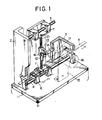
- Fig. 1 is a fragmentary perspective view showing a representative prior-art shearing machine used to cut off material being continuously fed into predetermined lengths;
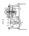
- Fig. 2 is a front view partly in section of a shearing machine according to the present invention;
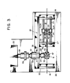
- Fig. 3 is a fragmentary plan view of the shearing machine according to the present invention;
- Fig. 4 is a cross-sectional view taken along the lines IV-IV in Fig. 2;
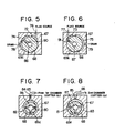
- Fig. 5 is a cross-sectional view taken along the lines V-V in Fig. 4;
- Fig. 6 is a cross-sectional view taken along the lines VI-VI in Fig. 4;
- Fig. 7 is a cross-sectional view taken along the lines VII-VII in Fig. 4; and
- Fig. 8 is a cross-sectional view taken along the lines VIII-VIII in Fig. 4.
- First, a brief reference will be made to a representative prior art shearing machine used to cut off material being continuously fed into predetermined lengths, with reference to the attached drawings.
- In a pipe manufacturing installation for mass- producing, for instance, relatively thin-walled and relatively small-diameter electric-welded tubes, there is generally a shearing machine at the last stage of manufacture which can cut off material into predetermined lengths while the material is continuously being fed in a straight line at a constant speed.
- It is well known to use a shearing machine of the scotch-yoke type for the above-described purpose. As shown in Fig. 1, in a shearing machine of this type, two
horizontal guide rods support frames members 7 and 8 are slidably fitted to the twohorizontal guide rods spline axle 10 extending in the direction perpendicular to the feed direction of the material 4 to be cut is supported between the two horizontally-travellingmembers 7 and 8. Acutter holder 13, having amovable cutter 12 fixed thereon, is fitted to the movablecutter guide rod 10 so as to be movable up and down. A fixedcutter 11 is fixed to the lower travelling member 8. Therefore, thefixed cutter 11 can move horizontally along thehorizontal guide rod 6, and themovable cutter 12 can also move horizontally with the verticalcutter guide rod 10 and vertically along the verticalcutter guide rod 10. - To drive both the above-mentioned movable and fixed
cutters swivel arm 14 rotating in a vertical plane parallel to the line along which the material to be cut is continuously fed, one end of which is rotatably supported by thecutter holder 13 and the other end of which is fixedly supported by thedrive shaft 17 of anadjustable speed motor 16 fixed to amotor support frame 15 disposed basically perpendicular to the base frame 1. - In the prior-art shearing machine thus constructed, therefore, when the
swivel arm 14 is rotated counterclockwise (in Fig. 1) by themotor 16, themovable cutter 12 moves up and down with respect to the fixedcutter 11 to shear off the material 4 to be cut, and also both the movable and fixedcutters - In this case, even if the speed of the vertical movement of the
movable cutter 12 varies during a single cutting cycle, this may be allowed from the standpoint of prevention of damage to the cutters; however, if the speed of the horizontal movement of the movable andfixed cutters - As the
swivel arm 14 rotates in a constant circular motion, the horizontal speed of the cutters, that is, the horizontal component of the motion of thepivot pin 41 of theswivel arm 14 follows a cosine curve. Therefore, it is necessary to continuously vary the instantaneous revolution speed of themotor 16 so that the horizontal speed component of the cutters may match the constant horizontal speed of the material to be cut at least while the cutters are shearing the material. For instance, in the case where one-quarter revolution of theswivel arm 14 is required to shear off the material, it is necessary to continuously and accurately adjust the revolution speed of the motor through more than 40 percent in a very short period via an electrical motor speed adjusting device (not shown). - Thus, a relatively
powerful motor 16 must be used to ensure accurate speed control; the cut depth, in other words, the stroke of themovable cutter 12 is severely limited; and the speed adjustment range increases with the increasing depth of cut; the minimum length to which the material can be cut is limited. - To overcome these problems mentioned above, there is commonly employed another shearing machine in which two independent driving means are used, one for moving the cutters horizontally in the feed direction of the material to be cut and the other for moving the movable cutter vertically in the direction perpendicular thereto. In this case, usually, a double-acting hydraulic cylinder movable horizontally together with the movable and fixed cutters is used only to move the movable cutter vertically to cut the material. In this case, usually the double-acting hydraulic cylinder is controlled by electromagnetic valves which switch between charging a working fluid thereinto or discharging the fluid therefrom. In this prior-art shearing machine, however, since the hydraulic cylinder is irregularly delayed by more than 20 ms when the working fluid direction is switched by the electromagnetic valves, in the case where the speed feed of the material to be cut is about 120 m/min, it is impossible to accurately cut the material off into lengths, for instance, less than about 1.5 m.
- Following the above description, reference is now made to a preferred shearing machine embodying the present invention.
- With reference to Figs. 2, 3 and 4, the shearing machine for cutting material continuously fed at a constant speed into predetermined lengths embodying the present invention mainly comprises three sections: a reciprocating mechanism section 23 (quick-return motion mechanism) driven by a motor to move the movable and fixed cutters horizontally in the feed direction, a travelling assembly (24a) and double-acting hydraulic cylinder device (24b)
section 24 to drive the movable cutter vertically while being moved horizontally by the reciprocating mechanism, and a two-wayrotary valve section 25 driven by a motor to control the double-acting hydraulic cylinder section by switching the direction of a working fluid charged thereinto or discharged therefrom. - In the figures, the
reference numeral 26 denotes a bed, and thenumeral 20 denotes a set of frames including a firstrod support frame 27, a secondrod support frame 28, anauxiliary support frame 57 and abearing support frame 56. - The
reference numeral 22 denotes a motor fixed to thebed 26. Themotor 22 includes adrive shaft 58, one end of which is connected to acoupling 59 to drive thereciprocating mechanism section 23 and the other end of which is connected to agear 70 to drive the two-wayrotary valve section 25. - First will be described the
reciprocating mechanism section 23 for moving the movable and fixed cutters horizontally in the feed direction, with reference particularly to Figs. 2 and 3. - The torque of the
motor 22 is transmitted to a drivenshaft 53 through thecoupling 59. Thedrive shaft 53 is supported by abearing case 52 fixed to thebearing support frame 56. At one end of thedrive shaft 53 there is fixed acrank lever 54 rotatable about the center of thedrive shaft 53. To the outer end of thecrank lever 54 there is provided anaxle 55 to which aflying slide 51 is fitted. Through theflying slide 51 there is passed aslide link 47 rotatably supported by anaxle 50 fixed to aangled portion 26b projecting from ahole 26a formed in thebed 26. In Fig. 2, thenumeral 49 denotes a bearing bracket for supporting theslide link 47 on the angled portion. - Therefore, when the
drive shaft 53 rotates, thecrank lever 54 also rotates to move theflying slide 51 up and down, so that theslide link 47 oscillates within the range, shown by the dotted and dashed lines in Fig. 2, determined by the tangents to the path of theaxle 55, also in Fig. 2. These tangent positions divide the path ofaxle 55 into two unequal arc-lengths, the longer of which corresponds to the feed direction of thematerial 19 and the shorter of which constitutes a quick-return stroke of thereciprocating mechanism 23. To one end of the slide crank 47 there is connected a connectinglink 44 passing through aslot 46 in therod support frame 27 to move the travelling assembly and double-actingcylinder section 24 horizontally to which a set of movable and fixed cutters are attached. The reciprocating mechanism thus constructed is called a slider crank mechanism, a type of a quick-return mechanism. - Next will be described the travelling assembly and double-acting
hydraulic cylinder section 24.. - On the
bed 26 there are vertically disposed a pair ofrod supporting frames rod supporting frames guide rods 29 there is disposed a cylindrical travellingcase 30 extending vertically or perpendicular to the material feed direction at a position roughly midway therebetween. The cylindrical travellingcase 30 is supported, so as to be slidable in the material feed direction, by a guide block31 projecting horizontally at the upper position and by another guide block 32 projecting horizontally at the lower position. At the top of the travellingcase 30, there is fixed a fixedcutter holder 34 having ahole 33, through which thematerial 19 to be cut is passed, projecting from the top end of therod supporting frames cutter holder 34 is a part of acutter portion 21, to which a fixedcutter 36 having ahole 35 in the same shape as that of thehole 33 is fixed. In the body of the fixedcutter 36, there is formed a movablecutter insertion hole 37 corn-: municating with thehole 35 and extending in the longitudinal direction of the travellingcase 30. The cutting edge of themovable cutter 38 can be inserted into the movablecutter insertion hole 37 in order to cut the material 19 in cooperation with the fixedcutter 36. The base portion of themovable cutter 38 is fixed to themovable cutter holder 40 by abolt 39. Themovable cutter holder 40 is inserted into a hole formed in the central portion of a cylindricalmovable axle 41, which is slidably fitted to the bore of the travellingcase 30, and is fixed there by apin 42. Further, themovable axle 41, as described later, is moved up and down by the double-actinghydraulic cylinder 24 attached to the other end of the travellingcase 30. Near the midpoint of the above-mentioned travellingcase 30, there is disposed abracket 43 projecting toward the left as seen in Figs. 2 and 3. One end of the connectinglink 44 of a slider crank mechanism of the quick-return type, serving as the above-mentionedreciprocating mechanism 23, is pivotably fitted to thebracket 43 via a pin 45. The lower end of the above-mentioned travellingcase 30 is coaxially attached to the double-actinghydraulic cylinder 24. One end portion of apiston rod 60 actuable by thehydraulic cylinder 24 is connected integrally with the lower end of themovable axle 41. The base portion of thepiston rod 60 is formed integrally with apiston 62 slidably inserted into acylinder body 61. Via thispiston 62, thecylinder 61 is divided into a first chamber 61 a (the upper side in Figs. 2 and 4) and a second chamber 61 b (the lower side in Figs. 2 and 4). Afirst connection pipe 65 and asecond connection pipe 66 are connected toports cylinder body 61 so as to communicate with the chambers 61a and 61b in order to supply a high pressure working fluid, such as compressed air or pressurized oil, through therotary valve 25, as described later. Further, in Fig. 2, thereference numeral 30a denotes an air vent communicating with the atmosphere to relieve pressure due to motion of themovable axle 41 from the lower part of the travellingcase 30. Further, in this embodiment, an air muffler (not shown) is attached to the outside of thisair communication hole 30a, to reduce noise produced therefrom. - Briefly, when the working fluid is charged from the
second connection pipe 66 into the second chamber 61b and is discharged from the first chamber 61 a through thefirst connection pipe 65, thepiston 62 moves upward, so that themovable cutter 38 shears the material 19 in cooperation with the fixedcutter 36. In contrast with this operation, when the working fluid is charged from thefirst connection pipe 65 into the first chamber 61a and is discharged from thesecond chamber 61 through thesecond connection pipe 66, thepiston 62 moves downward, so that themovable cutter 38 is separated from thematerial 19. The working fluid is charged into or discharged from each chamber under the control of the two-wayrotary valve 25 in coordination with the horizontal movement of the travellingcase 30. - Next will be described the two-way
rotary valve 25 serving to operate the double-acting cylinder, that is, to move the movable cutter up and down. - The first and
second connection pipes rotary valve 25 driven by themotor 22. In more detail, thevalve body 67 of therotary valve 25 is mounted on thebed 26, as shown in Fig. 4. Within arotary compartment 68 formed within thisvalve body 67, there is rotatably housed a roughly cylindrical spool-like rotor 69, the outer diameter of which matches the inner diameter of therotary compartment 68. And, at either end of therotor 69, there are integrally providedaxle portions valve body 67, and to theaxle portion 69a projecting outside of thevalve 25 there is fitted a drivengear 71 engaging adriving gear 70 fixed to the closer end of therotary shaft 58 of themotor 22. Further, thegears rotary shaft 58 rotates in one-to-one synchronization with therotor 69; however, without being limited to this, it is possible to ensure appropriate rotary synchronization by using other transmission means such as a sprocket wheel and a chain or a timing pulley and a timing belt, etc. - As depicted in Figs. 4-8, the
rotor 69 is formed with a first large-diameter portion 69c having afirst uniradial passage 90, a first small-diameter portion 69d having a firsttriradial passage 80, a second large-diameter portion 69e with a second uniradial passage 91, and a second small-diameter portion 69f with a secondtriradial passage 81. Further, therotor 69 is so constructed that afirst communication hole 86 formed along the axis of the rotor communicates between thefirst uniradial passage 90 and the firsttriradial passage 80 and that asecond communication hole 87 formed along the axis of the rotor communicates between the second uniradial passage 91 and the secondtriradial passage 81. In this description, the expressions "uniradial" and "triradial" can be interpreted respectively to mean "comprising a single radius" and "comprising a plurality of separate radii". - The
valve body 67 is formed with afirst pressure port 76, afirst drain port 78, a first small arc-shapedpressure pocket 72 communicating with thefirst pressure port 76, and a first large arc-shapeddrain pocket 74 communicating with thefirst drain port 78 at the axial position where the first large-diameter portion 69c of the rotor is located. - Further, the
valve body 67 is formed with afirst output port 84 and a firstannular pocket 82 between the exterior of the first small-diameter portion 69d and the interior of thebody 67 communicating with thefirst output port 84 at the axial position where the first small-diameter portion 69d of the rotor is located. - Further, the
valve body 67 is formed with asecond pressure port 77, asecond drain port 79, a second small arc-shapedpressure pocket 73 communicating with thesecond pressure port 77 and a second large arc-shapeddrain pocket 75 communicating with thesecond drain port 79 at the axial position where the second large-diameter portion 69e of the rotor is located. - Furthermore, the
valve body 67 is formed with asecond output port 85 and a secondcircular pocket 83 communicating with thesecond output port 85 at the axial position where the second small-diameter portion 69f of the rotor is located. - The pressure pockets 72 and 73, the drain pockets 74 and 75, and the
uniradial passages 90 and 91 are radially dimensioned and positioned such that when either passage communicates with the corresponding pressure pocket, the other passage communicates with its corresponding drain pocket, and the drain pockets 74 and 75 cover more of the circumference of therotary valve 25 than the pressure pockets 72 and 73, as shown in Figs. 5 and 6. - The first and
second pressure ports - The
first output port 84 is connected to the first >chamber 61a a of the double-acting hydraulic cylinder through afirst connection pipe 65, and thesecond output port 85 is connected to the second chamber 61b of the double-acting hydraulic cylinder through asecond connection pipe 66. - Now follows a description of the operation of the shearing machine thus constructed according to the present invention:
- In order to shear a continuously-fed material with the shearing machine, the
material 19 to be cut first passes through thehole 33 formed in the fixedcutter holder 34 and thehole 36 of the fixedcutter 36. Next, thereciprocating mechanism 23 is operated by the adjustable-speed motor 22 at an oscillation rate according to the material feeding speed. When the connectinglink 44 of thereciprocating mechanism 23 moves horizontally, the travellingcase 30 and the double-actingcylinder 24 also move together horizontally along theguide rods 29. - The
rotary valve 25 is also rotated by the above-mentioned adjustable-speed motor 22 via thegears - Now, there is described the operation of the two-way
rotary valve 25 when themovable cutter 38 moves upward. A working fluid is fed from the high-pressure working fluid source through thesecond pressure port 77 of therotary valve 25, thesecond pressure pocket 73, the second uniradial passage 91, thesecond communication hole 87, the secondtriradial passage 81, the secondannular pocket 83 and thesecond output port 85, to thesecond connection pipe 66, and next charged into the second compartment 61 b in thecylinder body 61 through theport 64. Also, the working fluid within the first compartment 61a a of thecylinder body 61 is fed to therotary valve 25 through theport 63 and thefirst connection pipe 65, and next discharged through-thafirst output port 84 of therotary valve 25, the firstannular pocket 82, the firsttriradial passage 80, thefirst communication hole 86, thefirst uniradial passage 90, thefirst drain pocket 74 and thefirst drain port 78 into a drain tank. In response to the resulting pressure difference between the two chambers 61a and 61 b, themovable axle 41 moves upward in Figs. 2 and 4, so that themovable cutter 38 engages the fixedcutter 36 to cut off thematerial 19. The directions in which the fluid flows through each of the elements ofvalve 25 are shown by the arrows in Figs. 5-8. - In this cutting step, it is necessary to synchronize the horizontal speed of the movable and fixed cutters with that of the material to be cut, at least while the cutters are shearing the material and until the movable cutter clears the material after shearing. Accordingly, the
reciprocating mechanism 23 should be slightly offset in the direction of delaying the return stroke of thereciprocating mechanism 23 until after themovable cutter 38 clears thematerial 19. This offset can be adjusted to match material size and feed rate. - After the
cutter support portion 21 is moved to the uppermost position, since therotor 69 of therotary valve 25 continues to be rotated by themotor 22, in contrast with the case mentioned above, the working fluid is fed from the high pressure working fluid source, through thefirst pressure port 76 of therotary valve 25, thefirst pressure pocket 72, thefirst uniradial passage 90, thefirst communication hole 86, the firsttriradial passage 80, the firstannular pocket 82 and thefirst output port 84, to thefirst connection pipe 65, and next charged into the first chamber 61 a in thecylinder body 61 through theport 63. Also, working fluid within the second compartment 61 b of thecylinder body 61 is fed to therotary valve 25 through theport 64 and thesecond connection pipe 66, and next discharged through thesecond output port 85 of therotary valve 25, the secondannular pocket 83, the secondtriradial passage 81, thesecond communication hole 87, the first uniradial passage 91, thesecond drain pocket 75 and thesecond drain port 79 into a drain tank. In response to the resulting pressure difference, themovable axle 41 moves downward in Figs. 2 and 4, so that themovable cutter 38 separates from the fixed cutter. In this case, the directions in which the fluid flows through the elements of therotary valve 25 are those opposite to the directions shown by the arrows in Figs. 5-8. - Further, once the
movable cutter 38 is completely clear of thematerial 19, it is unnecessary to synchronize the horizontal speed of the movable and fixedcutters - Further, in the movement stroke range of the travelling
case 30 other than the range within which the travellingcase 30 moves in synchronization with the material feed speed to shearmaterial 19 to be cut, the working fluid within each chamber 61a a or 61b of the double-actingcylinder 24 is not charged into or discharged from the cylinder, because thefirst uniradial passage 90 communicates with neither thefirst pressure port 72 nor thefirst drain pocket 74 in therotary valve 25 and also because the second uniradial passage 91 communicates with neither thesecond pressure port 73 nor thesecond drain pocket 75 in therotary valve 25. Since the movement described above is repeated, it is possible to repeatedly cut the material 19 into appropriate predetermined lengths accurately. - As described above, in the shearing machine embodying the present invention, since the cutter supporting portion is moved horizontally along a plurality of guide rods by the reciprocating mechanism driven by the motor so as to match with the feed speed of the material to be cut and is moved vertically along the travelling case by the double-acting cylinder so as to cut off the material to be cut and since -the double-acting cylinder is operated by the working fluid controlled through the two-way rotary valve driven by the motor in conjunction with the movement of the reciprocating mechanism, it is possible to accurately synchronize the horizontal speed of the cutter supporting portion with the feed speed of the material to be cut during the shear cycle, and to cut the material into short lengths with relatively low power.
- Further, since the two-way rotary valve is mechanically driven by the motor directly without using any electromagnetic valves, it is possible to control the double-acting hydraulic cylinder quickly without appreciable response delay, in otherwords, to cut the material into short lengths, accurately.
- It will be understood by those skilled in the art that the foregoing description is in terms of preferred embodiments of the present invention wherein various changes and modifications may be made without departing from the spirit and scope of the invention, as is set forth in the appended claims.
Claims (6)
Applications Claiming Priority (2)
| Application Number | Priority Date | Filing Date | Title |
|---|---|---|---|
| JP55181080A JPS5933486B2 (en) | 1980-12-20 | 1980-12-20 | shearing machine |
| JP181080/80 | 1980-12-20 |
Publications (3)
| Publication Number | Publication Date |
|---|---|
| EP0055096A2 EP0055096A2 (en) | 1982-06-30 |
| EP0055096A3 EP0055096A3 (en) | 1984-05-02 |
| EP0055096B1 true EP0055096B1 (en) | 1986-11-12 |
Family
ID=16094453
Family Applications (1)
| Application Number | Title | Priority Date | Filing Date |
|---|---|---|---|
| EP81305953A Expired EP0055096B1 (en) | 1980-12-20 | 1981-12-18 | Shearing machine |
Country Status (5)
| Country | Link |
|---|---|
| US (1) | US4437372A (en) |
| EP (1) | EP0055096B1 (en) |
| JP (1) | JPS5933486B2 (en) |
| CA (1) | CA1176971A (en) |
| DE (1) | DE3175588D1 (en) |
Families Citing this family (13)
| Publication number | Priority date | Publication date | Assignee | Title |
|---|---|---|---|---|
| JPS5932316U (en) * | 1982-08-23 | 1984-02-28 | 株式会社明電舎 | shearing machine |
| US4643063A (en) * | 1985-08-01 | 1987-02-17 | Mckenica Inc. | Tube cutoff machine |
| JPS62116786U (en) * | 1985-09-26 | 1987-07-24 | ||
| CA1292022C (en) * | 1986-07-14 | 1991-11-12 | Friedhelm Mundus | Apparatus for moving a carriage or the like in one direction over a predetermined distance at a substantially uniform velocity and for returning the carriage at a varying velocity |
| US4771668A (en) * | 1986-10-23 | 1988-09-20 | The Goodyear Tire & Rubber Company | Cutting an elongated member into sections |
| US5243889A (en) * | 1991-04-09 | 1993-09-14 | Wallis Bernard J | Tube cut off machine |
| SE514893C2 (en) * | 1998-11-18 | 2001-05-14 | Hydropulsor Ab | Method and device for impact on a moving object |
| WO2001028865A1 (en) * | 1999-10-20 | 2001-04-26 | S.P.C. Limited | Cutting assembly and seal integrity monitoring system for a filling and heat sealing line |
| IT1319208B1 (en) * | 2000-10-13 | 2003-09-26 | Sacma Macchine Per Lamiera S P | SHEAR FOR CUTTING SHEETS AND SIMILAR. |
| EP1815972B1 (en) * | 2006-02-06 | 2013-12-18 | ABB Research Ltd. | Press line system and method |
| PL2942150T3 (en) * | 2014-05-07 | 2019-07-31 | Fives Oto S.P.A. | Machine for cutting a moving object |
| CN105196338A (en) * | 2015-10-21 | 2015-12-30 | 无锡港盛重型装备有限公司 | Program-control hydraulic splitting machine |
| CN106077795A (en) * | 2016-07-29 | 2016-11-09 | 浙江中创科技有限公司 | Sheet material follow-up cutting device |
Family Cites Families (6)
| Publication number | Priority date | Publication date | Assignee | Title |
|---|---|---|---|---|
| GB1143648A (en) * | ||||
| US3292472A (en) * | 1964-07-22 | 1966-12-20 | Joseph F Mckenica & Son Inc | Automobile tube cutoff apparatus |
| US3581616A (en) * | 1967-09-23 | 1971-06-01 | Nippon Steel Corp | Method and apparatus for high speed cutting of shaped steel |
| FR2304431A1 (en) * | 1975-03-20 | 1976-10-15 | Metallurg Revigny | Shear for drawing machine - with material gripped by vice on sliding carriage and cut by hydraulically operated vertically movable blades |
| US4191078A (en) * | 1978-02-03 | 1980-03-04 | Orion Machinery & Engineering Corp. | Wire cutting flying shear |
| DE2915503A1 (en) * | 1979-04-17 | 1980-10-30 | Keller Maschinenbau Gmbh Geb | Flying shears for seam welded tube - are actuated hydraulically through cylinders connected by flexible pipes to pump |
-
1980
- 1980-12-20 JP JP55181080A patent/JPS5933486B2/en not_active Expired
-
1981
- 1981-12-14 CA CA000392256A patent/CA1176971A/en not_active Expired
- 1981-12-16 US US06/331,327 patent/US4437372A/en not_active Expired - Fee Related
- 1981-12-18 DE DE8181305953T patent/DE3175588D1/en not_active Expired
- 1981-12-18 EP EP81305953A patent/EP0055096B1/en not_active Expired
Also Published As
| Publication number | Publication date |
|---|---|
| EP0055096A3 (en) | 1984-05-02 |
| JPS5933486B2 (en) | 1984-08-16 |
| DE3175588D1 (en) | 1987-01-02 |
| JPS57107723A (en) | 1982-07-05 |
| EP0055096A2 (en) | 1982-06-30 |
| CA1176971A (en) | 1984-10-30 |
| US4437372A (en) | 1984-03-20 |
Similar Documents
| Publication | Publication Date | Title |
|---|---|---|
| EP0055096B1 (en) | Shearing machine | |
| US4301723A (en) | Cylinder operated swinging ram cutoff press | |
| US4228706A (en) | Swinging ram cut-off machine | |
| US4462741A (en) | Pressing machine with a built-in robot | |
| KR910008902B1 (en) | Dimpleless tube cutting apparatus | |
| US3736826A (en) | Apparatus for shearing uniform charges of glass from a molten stream of glass | |
| US3974726A (en) | Cutter for bar stock | |
| US3972216A (en) | Reciprocating press | |
| US4939967A (en) | Cut-off machine | |
| US2414906A (en) | Sheet feeding and notching | |
| GB1473406A (en) | Starter slide and blade assembly for a thread rolling machine | |
| US5492000A (en) | Rotary valve controlled apparatus for stripping cans from bodymaking ram | |
| US2218970A (en) | Molten glass severing mechanism | |
| US2241414A (en) | Forming machine | |
| US3183532A (en) | Automatic transfer mechanism for forging machines | |
| CN212469989U (en) | Cutter is used in chain production | |
| CN218984931U (en) | Surface treatment device for refrigerator sealing strip | |
| CA1083949A (en) | Cylinder operated swinging ram cutoff press | |
| JPH0347712Y2 (en) | ||
| SU1712038A1 (en) | Apparatus for forming long materials | |
| JP2532040B2 (en) | Transfer device of bottle body in bottle making machine | |
| US6408671B1 (en) | Hydromechanical drive of a cross-shearing station | |
| SU967624A1 (en) | Apparatus for feeding blanks into press working zone | |
| US4347961A (en) | Rapid advance long dwell feed mechanism for multiple slide machines | |
| US919274A (en) | Attachment for diamond lath-machines. |
Legal Events
| Date | Code | Title | Description |
|---|---|---|---|
| PUAI | Public reference made under article 153(3) epc to a published international application that has entered the european phase |
Free format text: ORIGINAL CODE: 0009012 |
|
| AK | Designated contracting states |
Designated state(s): DE GB |
|
| 17P | Request for examination filed |
Effective date: 19830309 |
|
| PUAL | Search report despatched |
Free format text: ORIGINAL CODE: 0009013 |
|
| AK | Designated contracting states |
Designated state(s): DE GB |
|
| GRAA | (expected) grant |
Free format text: ORIGINAL CODE: 0009210 |
|
| AK | Designated contracting states |
Kind code of ref document: B1 Designated state(s): DE GB |
|
| REF | Corresponds to: |
Ref document number: 3175588 Country of ref document: DE Date of ref document: 19870102 |
|
| PLBE | No opposition filed within time limit |
Free format text: ORIGINAL CODE: 0009261 |
|
| STAA | Information on the status of an ep patent application or granted ep patent |
Free format text: STATUS: NO OPPOSITION FILED WITHIN TIME LIMIT |
|
| 26N | No opposition filed | ||
| PGFP | Annual fee paid to national office [announced via postgrant information from national office to epo] |
Ref country code: GB Payment date: 19900131 Year of fee payment: 9 |
|
| PGFP | Annual fee paid to national office [announced via postgrant information from national office to epo] |
Ref country code: DE Payment date: 19900213 Year of fee payment: 9 |
|
| PG25 | Lapsed in a contracting state [announced via postgrant information from national office to epo] |
Ref country code: GB Effective date: 19901218 |
|
| GBPC | Gb: european patent ceased through non-payment of renewal fee | ||
| PG25 | Lapsed in a contracting state [announced via postgrant information from national office to epo] |
Ref country code: DE Effective date: 19910903 |