US4643063A - Tube cutoff machine - Google Patents
Tube cutoff machine Download PDFInfo
- Publication number
- US4643063A US4643063A US06/761,752 US76175285A US4643063A US 4643063 A US4643063 A US 4643063A US 76175285 A US76175285 A US 76175285A US 4643063 A US4643063 A US 4643063A
- Authority
- US
- United States
- Prior art keywords
- tube
- carriage
- location
- speed
- shearing
- Prior art date
- Legal status (The legal status is an assumption and is not a legal conclusion. Google has not performed a legal analysis and makes no representation as to the accuracy of the status listed.)
- Expired - Fee Related
Links
Images


Classifications
-
- B—PERFORMING OPERATIONS; TRANSPORTING
- B23—MACHINE TOOLS; METAL-WORKING NOT OTHERWISE PROVIDED FOR
- B23D—PLANING; SLOTTING; SHEARING; BROACHING; SAWING; FILING; SCRAPING; LIKE OPERATIONS FOR WORKING METAL BY REMOVING MATERIAL, NOT OTHERWISE PROVIDED FOR
- B23D25/00—Machines or arrangements for shearing stock while the latter is travelling otherwise than in the direction of the cut
- B23D25/02—Flying shearing machines
- B23D25/04—Flying shearing machines in which a cutting unit moves bodily with the work while cutting
-
- B—PERFORMING OPERATIONS; TRANSPORTING
- B23—MACHINE TOOLS; METAL-WORKING NOT OTHERWISE PROVIDED FOR
- B23D—PLANING; SLOTTING; SHEARING; BROACHING; SAWING; FILING; SCRAPING; LIKE OPERATIONS FOR WORKING METAL BY REMOVING MATERIAL, NOT OTHERWISE PROVIDED FOR
- B23D21/00—Machines or devices for shearing or cutting tubes
-
- Y—GENERAL TAGGING OF NEW TECHNOLOGICAL DEVELOPMENTS; GENERAL TAGGING OF CROSS-SECTIONAL TECHNOLOGIES SPANNING OVER SEVERAL SECTIONS OF THE IPC; TECHNICAL SUBJECTS COVERED BY FORMER USPC CROSS-REFERENCE ART COLLECTIONS [XRACs] AND DIGESTS
- Y10—TECHNICAL SUBJECTS COVERED BY FORMER USPC
- Y10T—TECHNICAL SUBJECTS COVERED BY FORMER US CLASSIFICATION
- Y10T83/00—Cutting
- Y10T83/465—Cutting motion of tool has component in direction of moving work
- Y10T83/4653—With means to initiate intermittent tool action
- Y10T83/4656—Tool moved in response to work-sensing means
- Y10T83/4676—With work-responsive means to initiate flying movement of tool
- Y10T83/4682—With means controlling flying speed dependent on work speed
-
- Y—GENERAL TAGGING OF NEW TECHNOLOGICAL DEVELOPMENTS; GENERAL TAGGING OF CROSS-SECTIONAL TECHNOLOGIES SPANNING OVER SEVERAL SECTIONS OF THE IPC; TECHNICAL SUBJECTS COVERED BY FORMER USPC CROSS-REFERENCE ART COLLECTIONS [XRACs] AND DIGESTS
- Y10—TECHNICAL SUBJECTS COVERED BY FORMER USPC
- Y10T—TECHNICAL SUBJECTS COVERED BY FORMER US CLASSIFICATION
- Y10T83/00—Cutting
- Y10T83/465—Cutting motion of tool has component in direction of moving work
- Y10T83/4737—With tool speed regulator
-
- Y—GENERAL TAGGING OF NEW TECHNOLOGICAL DEVELOPMENTS; GENERAL TAGGING OF CROSS-SECTIONAL TECHNOLOGIES SPANNING OVER SEVERAL SECTIONS OF THE IPC; TECHNICAL SUBJECTS COVERED BY FORMER USPC CROSS-REFERENCE ART COLLECTIONS [XRACs] AND DIGESTS
- Y10—TECHNICAL SUBJECTS COVERED BY FORMER USPC
- Y10T—TECHNICAL SUBJECTS COVERED BY FORMER US CLASSIFICATION
- Y10T83/00—Cutting
- Y10T83/465—Cutting motion of tool has component in direction of moving work
- Y10T83/4757—Tool carrier shuttles rectilinearly parallel to direction of work feed
- Y10T83/4763—Both members of cutting pair on same carrier
-
- Y—GENERAL TAGGING OF NEW TECHNOLOGICAL DEVELOPMENTS; GENERAL TAGGING OF CROSS-SECTIONAL TECHNOLOGIES SPANNING OVER SEVERAL SECTIONS OF THE IPC; TECHNICAL SUBJECTS COVERED BY FORMER USPC CROSS-REFERENCE ART COLLECTIONS [XRACs] AND DIGESTS
- Y10—TECHNICAL SUBJECTS COVERED BY FORMER USPC
- Y10T—TECHNICAL SUBJECTS COVERED BY FORMER US CLASSIFICATION
- Y10T83/00—Cutting
- Y10T83/869—Means to drive or to guide tool
- Y10T83/8789—With simple revolving motion only
- Y10T83/8791—Tool mounted on radial face of rotor
Definitions
- the present invention relates to a machine for cutting a continuously moving tube to precise lengths, and more specifically wherein the cutting of the tube can be performed while the tube is moving at speeds up to 500' per minute.
- Heat exchanger tubes which are used in automobile radiators are typically manufactured in a tubing mill, the tube as it exits from the mill being cut to precise repeatable lengths, for example 21".
- Various machines have been developed for cutting the tubes to length and one such machine is shown in U.S. Pat. No. 3,292,472 issued Dec. 20, 1966. While the aforesaid patent could precisely cut tubes to repeatable lengths, the apparatus of said patent was limited to use with tube mills wherein the speed of the tube as it exited from a tube mill did not exceed 210' per minute.
- Recently tube cutting machines have been developed which can operate at higher tube speeds, one being shown in U.S. Pat. No.
- a frame which supports a carriage for generally linear reciprocal movement between first and second locations parallel to the linear path of movement of a tube which may exit from a tube mill.
- the carriage is reciprocated by a crank drive mechanism and supports a tube shearing apparatus.
- Connecting means are provided which connect the crank drive mechanism with the carriage in such a manner that the carriage will be caused to be moved at a constant linear speed for a duration of time sufficient to shear the tube as the carriage moves from the first location to the second location.
- shear operating means are provided which are capable of operating the shearing apparatus when the carriage is being moved at said constant linear speed.
- the connecting means includes a bell crank having an intermediate portion which is pivotally secured to the carriage, one end of a connecting rod, which is part of the rotating crank drive mechanism, being secured to one end of the bell crank, and the other end of the bell crank being provided with a cam follower which is caused to engage a stationary cam.
- the tube shearing apparatus includes a rotating disk, a tube shearing knife carried by the disk, and a die through which the tube passes, the knife also passing through the die during the shearing apparatus.
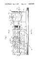
- FIG. 1 is a side view of a tube cutting apparatus employing the novel features of this invention.
- FIG. 2 is a top view of the apparatus shown in FIG. 1.
- FIGS. 3, 4 and 5 are sections taken generally along the lines 3--3, 4--4, and 5--5 in FIG. 1.
- FIG. 6 is a section taken generally along the line 6--6 in FIG. 3.
- a tube 10 is illustrated, which tube can be exiting from a tubing mill and will be passing through the tube cutting apparatus of this invention along a predetermined generally linear path.
- the tube as it exits from the tubing mill will be in a flat form and could be formed either by welding, or by lock seaming.
- the tube will be moving at a generally high rate of speed, for example 440' per minute, initially past a first location, indicated by the dot dash line 12 and then past a second location indicated by the dot dash line 14.
- the tubing mill is not illustrated as such machines are relatively well known in the art.
- the apparatus of the present invention includes a frame, indicated generally at 16, upon which various components are mounted.
- the frame includes a base plate 18, a gear box support 20 and first and second spaced apart vertical support members 22, 24.
- Upper and lower cylindrical rails 26, 28 extend between the first and second vertical support members 22, 24, respectively.
- the cylindrical rails are mounted in such a manner that they are parallel to the predetermined generally linear path of travel of the tube 10.
- the support members 22 and 24 are provided with axially aligned bearings in which a spline shaft 30 is journaled, the spline shaft also being parallel to the predetermined generally linear path of travel of the tube.
- the spline shaft may have a single spline or keyway as illustrated, or may have a plurality of splines.
- variable speed electric motor 32 (FIG. 2), a double output shaft gear box, indicated generally at 34, and a carriage indicated generally at 36.
- a tube speed sensor 38 and a motor control means 40 may also be mounted on the frame.
- the tube speed sensor 38 senses the speed of the moving tube and the motor control means causes the output speed of the motor 32 to be proportional to the speed of the tube and the length of cut in a manner which will be more fully brought out below.
- the double output shaft gear box 34 includes an enclosure 42, there being an input shaft 44 (FIG. 2) which extends to one side of the enclosure, an output shaft 46 (FIG. 1) at right angles to the input shaft, and a second output shaft 48 which is coaxial with the input shaft.
- a driven gear 50 is mounted upon the input shaft 44, the driven gear 50 being in turn in mesh with a drive gear 52 mounted upon the output shaft 54 of the motor 32.
- the first output shaft 46 of the gear box 34 carries a drive wheel 56 for rotation with the output shaft 46, the drive wheel in turn forming part of a rotating crank drive mechanism indicated generally at 58.
- the drive wheel 56 is provided with a radially extending slot 60 which may receive pin means 62.
- the pin means can be secured to the drive wheel at varying fixed locations spaced away from the axis of rotation of the drive wheel.
- the rotating crank drive mechanism further includes a connecting rod 64 one end 66 of which is journaled about the pin means 62.
- the carriage includes a vertically extending frame member 68 provided with upper and lower linear bearings 70, 72 which are disposed about the cylindrical rails 26, 28, respectively.
- upper and lower transversely extending members 74, 76 are provided, one end of each of the members being welded or otherwise rigidly secured to an associated linear bearing, and the other ends of the transversely extending members 74, 76 being rigidly secured to a hub 78.
- the carriage further includes a transversely extending vertical plate 80 which is welded to or otherwise rigidly secured to the frame member 68, the upper and lower transversely extending member 74, 76, and hub 78.
- a tube shearing apparatus is supported on the carriage.
- the tube shearing apparatus includes a rotating disk 84, a tube shearing knife 86 which is secured to the disk 84 by fasteners 88, and a die 90 which is bolted to the transversely extending vertical plate 80 by bolts 92.
- the die is provided with a suitable aperture for the reception of the tube 10 and similarly the plate 80 is also provided with suitable aperture 94 through which the tube 10 may pass.
- the knife 86 may also pass between spaced apart locations of the die 90 for the purpose of severing the tube.
- spline bushings Mounted upon the spline shaft 30 are a pair of spline bushings, there being a right hand spline bushing 96 and a left hand spline bushing 98.
- Each of the spline bushings is provided with a flange 100 and the flanges 100 of each of the bushings is secured to the other flange by means of fasteners 102.
- a ring 104 Disposed between the flanges is a ring 104 which is in turn supported within the hub 78. It should be apparent from an inspection of FIG.
- the bushings 96 and 98 can rotate with respect to the hub 78 but will cause the hub to be moved along the spline shaft 30 as the carriage is moved from the first to the second position and then back to the first position.
- the disk 84 is in turn rigidly secured to the flange 100 of the right spline bushing 96. Thus, the disk 84 will be caused to be rotated when the spline shaft 30 is rotated.
- the spline shaft 30 forms part of a shear operating means, the shaft 30 in turn being operated by means of a driven gear 106 mounted upon the right hand end of the shaft 30.
- the gear 106 is in turn caused to be driven by a drive gear 107 mounted upon the output shaft 48 of the double output shaft gear box 34.
- Connecting means are provided for connecting the rotating crank drive mechanism 58 with the carriage 36.
- the connecting means includes a bell crank indicated generally at 110 in FIG. 4.
- An intermediate portion 112 of the bell crank is secured to a bushing 114 rotatably supported by the frame member 68 of the carriage 36.
- one arm 116 of the bell crank is disposed to one side of the frame member 68 and the other arm 118 is disposed to the other side of the frame member 68.
- the arm 118 is provided with a suitable hub 120 which is disposed about the bushing 114 and is pinned to the bushing 114 and intermediate portion 112 by means of a pin 122.
- a portion of the arm 116 remote from the intermediate portion 112 of the bell crank is provided with a pivot pin 124 (FIG. 1) about which the other end 126 of the connecting rod is journaled.
- the end of the other bell crank arm 118 remote from the intermediate portion 112 is in turn provided with a cam follower 128, the cam follower being rotatably mounted on the arm for rotation about bolt 130.
- the cam follower is adapted to engage a cam surface 132 (FIG. 1) which is formed on the upper surface of a plate 134 (FIG. 3) which is rigidly secured to the base plate 18 by means of bracket 136.
- the cam follower 128 is caused to bear against the cam surface 132 by means of a spring 138 one end of which engages the arm 116 of the bell crank at a position above the pivot pin 124, the other end of the spring being secured to a bracket 140 carried by the frame member 68.
- the length of the tube cut by the apparatus of this invention is preferably varied by varying the distance of the pin means 62 from the axis of the drive wheel.
- the pin means is spaced away from the axis a distance equal to 12" divided by ⁇ so that the circumference traveled by the pin means 62 is 12".
- the cut length is to be 24
- the circumference traveled by the connecting pin 62 is set at 24".
- the RPM of the drive wheel is proportional to the speed of the tube and inversely proportional to the circumference.
- the RPM of the drive wheel 56 should be 175 (350 divided by the two foot circumference).
- the tube speed is 200' per minute, the RPM of the drive wheel should be 100 (200 divided by the two foot circumference).
- the cam mechanism will ensure that the speed of the shuttle is exactly the same as the tube speed during the 21/2" of movement provided that the circumference traveled by the pin means 62 and the RPM's of the drive wheel 56 are properly adjusted.
- the length of cut will be inputted into the motor control means by the operator after the pin means has been set to the proper location, and once the apparatus starts running the speed sensor will maintain the proper rpm of the drive wheel.
- the carriage of this invention can be caused to be moved at the same linear speed as the tube to be cut during a portion of the cutting operation.
- the length of time that the knife is actually engaging the tube may be shortened as it is not necessary to decelerate the knife and to then reverse its direction of rotation as in prior art designs.
- the cam design of this mechanism is of a relatively lower cost than prior art cam designs, and yet is of a highly reliable design.
Abstract
Description
Claims (8)
Priority Applications (1)
| Application Number | Priority Date | Filing Date | Title |
|---|---|---|---|
| US06/761,752 US4643063A (en) | 1985-08-01 | 1985-08-01 | Tube cutoff machine |
Applications Claiming Priority (1)
| Application Number | Priority Date | Filing Date | Title |
|---|---|---|---|
| US06/761,752 US4643063A (en) | 1985-08-01 | 1985-08-01 | Tube cutoff machine |
Publications (1)
| Publication Number | Publication Date |
|---|---|
| US4643063A true US4643063A (en) | 1987-02-17 |
Family
ID=25063175
Family Applications (1)
| Application Number | Title | Priority Date | Filing Date |
|---|---|---|---|
| US06/761,752 Expired - Fee Related US4643063A (en) | 1985-08-01 | 1985-08-01 | Tube cutoff machine |
Country Status (1)
| Country | Link |
|---|---|
| US (1) | US4643063A (en) |
Cited By (6)
| Publication number | Priority date | Publication date | Assignee | Title |
|---|---|---|---|---|
| US4939967A (en) * | 1987-04-27 | 1990-07-10 | Wallis Bernard J | Cut-off machine |
| EP0440327A2 (en) * | 1990-01-08 | 1991-08-07 | Bernard Joseph Wallis | Cut-off machine and method for tubing |
| US5243889A (en) * | 1991-04-09 | 1993-09-14 | Wallis Bernard J | Tube cut off machine |
| US5301584A (en) * | 1993-03-15 | 1994-04-12 | Touchstone, Inc. | Zero clearance high speed welded seam tube cut-off die |
| US9698650B2 (en) | 2014-06-02 | 2017-07-04 | Regal Beloit America, Inc. | Electric device, gearbox and associated method |
| CN107283493A (en) * | 2017-07-25 | 2017-10-24 | 许坚玉 | A kind of plastic round tube cutting means |
Citations (12)
| Publication number | Priority date | Publication date | Assignee | Title |
|---|---|---|---|---|
| US789776A (en) * | 1903-08-08 | 1905-05-16 | Edward L White | Cutting mechanism. |
| US1726256A (en) * | 1924-11-29 | 1929-08-27 | Muller J C & Co | Rod cigarette machine |
| US2953955A (en) * | 1957-01-14 | 1960-09-27 | Denton W Underhill | Compact adjustable length tubing cutter |
| US3114282A (en) * | 1958-04-05 | 1963-12-17 | Reifenhauser K G | Apparatus for the transverse severance of continuously moving tubular structures |
| US3292472A (en) * | 1964-07-22 | 1966-12-20 | Joseph F Mckenica & Son Inc | Automobile tube cutoff apparatus |
| US3827323A (en) * | 1967-08-23 | 1974-08-06 | Meyer Roth Pastor Maschf | Overhung shear |
| US4114490A (en) * | 1976-08-14 | 1978-09-19 | L. Schuler Gmbh | Strip material dividing device |
| US4191078A (en) * | 1978-02-03 | 1980-03-04 | Orion Machinery & Engineering Corp. | Wire cutting flying shear |
| US4383172A (en) * | 1981-01-23 | 1983-05-10 | Twin City International, Inc. | Method and apparatus for measuring coating thicknesses on continuously moving material |
| US4437372A (en) * | 1980-12-20 | 1984-03-20 | Kabushiki Kaisha Meidensha | Shearing machine |
| US4451732A (en) * | 1982-05-20 | 1984-05-29 | Twin City International, Inc. | Apparatus for measuring thickness of coating on continuously moving material |
| US4462290A (en) * | 1982-10-27 | 1984-07-31 | Wallis Bernard J | Tube cut-off machine |
-
1985
- 1985-08-01 US US06/761,752 patent/US4643063A/en not_active Expired - Fee Related
Patent Citations (12)
| Publication number | Priority date | Publication date | Assignee | Title |
|---|---|---|---|---|
| US789776A (en) * | 1903-08-08 | 1905-05-16 | Edward L White | Cutting mechanism. |
| US1726256A (en) * | 1924-11-29 | 1929-08-27 | Muller J C & Co | Rod cigarette machine |
| US2953955A (en) * | 1957-01-14 | 1960-09-27 | Denton W Underhill | Compact adjustable length tubing cutter |
| US3114282A (en) * | 1958-04-05 | 1963-12-17 | Reifenhauser K G | Apparatus for the transverse severance of continuously moving tubular structures |
| US3292472A (en) * | 1964-07-22 | 1966-12-20 | Joseph F Mckenica & Son Inc | Automobile tube cutoff apparatus |
| US3827323A (en) * | 1967-08-23 | 1974-08-06 | Meyer Roth Pastor Maschf | Overhung shear |
| US4114490A (en) * | 1976-08-14 | 1978-09-19 | L. Schuler Gmbh | Strip material dividing device |
| US4191078A (en) * | 1978-02-03 | 1980-03-04 | Orion Machinery & Engineering Corp. | Wire cutting flying shear |
| US4437372A (en) * | 1980-12-20 | 1984-03-20 | Kabushiki Kaisha Meidensha | Shearing machine |
| US4383172A (en) * | 1981-01-23 | 1983-05-10 | Twin City International, Inc. | Method and apparatus for measuring coating thicknesses on continuously moving material |
| US4451732A (en) * | 1982-05-20 | 1984-05-29 | Twin City International, Inc. | Apparatus for measuring thickness of coating on continuously moving material |
| US4462290A (en) * | 1982-10-27 | 1984-07-31 | Wallis Bernard J | Tube cut-off machine |
Non-Patent Citations (2)
| Title |
|---|
| Model MSH 6, Tube Cutoff Machine Brochure, McKenica, Inc., Buffalo, NY. * |
| Model MSH-6, Tube Cutoff Machine Brochure, McKenica, Inc., Buffalo, NY. |
Cited By (9)
| Publication number | Priority date | Publication date | Assignee | Title |
|---|---|---|---|---|
| US4939967A (en) * | 1987-04-27 | 1990-07-10 | Wallis Bernard J | Cut-off machine |
| US5063801A (en) * | 1989-01-23 | 1991-11-12 | Wallis Bernard J | Cut-off machine and method for tubing |
| EP0440327A2 (en) * | 1990-01-08 | 1991-08-07 | Bernard Joseph Wallis | Cut-off machine and method for tubing |
| EP0440327A3 (en) * | 1990-01-08 | 1991-12-27 | Bernard Joseph Wallis | Cut-off machine and method for tubing |
| US5243889A (en) * | 1991-04-09 | 1993-09-14 | Wallis Bernard J | Tube cut off machine |
| US5311802A (en) * | 1991-04-09 | 1994-05-17 | Wallis Bernard J | Tube cut off machine |
| US5301584A (en) * | 1993-03-15 | 1994-04-12 | Touchstone, Inc. | Zero clearance high speed welded seam tube cut-off die |
| US9698650B2 (en) | 2014-06-02 | 2017-07-04 | Regal Beloit America, Inc. | Electric device, gearbox and associated method |
| CN107283493A (en) * | 2017-07-25 | 2017-10-24 | 许坚玉 | A kind of plastic round tube cutting means |
Similar Documents
| Publication | Publication Date | Title |
|---|---|---|
| US4240312A (en) | Apparatus for improving wear life of rotary die cutter anvil covers | |
| KR900003644B1 (en) | Machine for slitting continuous tapes into stripes in partticular with cutting cylinders having variable site | |
| US3869948A (en) | Shear apparatus | |
| US4643063A (en) | Tube cutoff machine | |
| US4215609A (en) | Slitter scorer having upper and lower pairs of shafts selectively rotated by a single drive | |
| FI108336B (en) | Device for cutting spirally wound metal tubes | |
| US5311802A (en) | Tube cut off machine | |
| US4866970A (en) | Apparatus for the continuous shearing off and cold swaging of metal workpieces | |
| US3863536A (en) | Cutting Guide for Machines for Producing Rods, Particularly for Cigarette Machines | |
| CN1108981A (en) | High speed shear for end trimming rods and the like | |
| US3690208A (en) | Variable speed drive mechanism | |
| US3791244A (en) | Shearing machine for cutting of band material | |
| US4939967A (en) | Cut-off machine | |
| US2709846A (en) | Flying saw | |
| US3308701A (en) | Floating shears for sectioning material, especially rolling stock material | |
| CN214978213U (en) | Wind power tower cylinder steel sheet cutting device | |
| US4856396A (en) | Apparatus for selectively forming apertures or holes or venting pinholes in a continuously moving web | |
| WO1997005992A1 (en) | Slotter wheel mechanism having selectively rotatable slotter blades | |
| US2452343A (en) | Apparatus for hot sawing | |
| US3859881A (en) | Stock cutting apparatus | |
| US3960099A (en) | Can trimming apparatus | |
| JPH0478407B2 (en) | ||
| US4446899A (en) | Double-sided tenoner | |
| US2899737A (en) | Cutting apparatus | |
| US919510A (en) | Edgewise-winding machine. |
Legal Events
| Date | Code | Title | Description |
|---|---|---|---|
| AS | Assignment |
Owner name: MCKENICA INC., 398 LUDINGTON STREET, BUFFALO, NEW Free format text: ASSIGNMENT OF ASSIGNORS INTEREST.;ASSIGNOR:GOBIEN, ERIC W.;REEL/FRAME:004439/0216 Effective date: 19850801 |
|
| FEPP | Fee payment procedure |
Free format text: PAYOR NUMBER ASSIGNED (ORIGINAL EVENT CODE: ASPN); ENTITY STATUS OF PATENT OWNER: SMALL ENTITY |
|
| AS | Assignment |
Owner name: INSILCO CORPORATION, A CT CORP. Free format text: ASSIGNMENT OF ASSIGNORS INTEREST.;ASSIGNOR:MCKENICA, INC.;REEL/FRAME:005036/0048 Effective date: 19881206 Owner name: INSILCO CORPORATION, CONNECTICUT Free format text: ASSIGNMENT OF ASSIGNORS INTEREST;ASSIGNOR:MCKENICA, INC.;REEL/FRAME:005036/0048 Effective date: 19881206 |
|
| AS | Assignment |
Owner name: BANKERS TRUST COMPANY, A NEW YORK BANKING CORP. Free format text: SECURITY INTEREST;ASSIGNOR:INSILCO CORPORATION;REEL/FRAME:005014/0127 Effective date: 19881212 Owner name: WELLS FARGO BANK, N.A., Free format text: SECURITY INTEREST;ASSIGNOR:INSILCO CORPORATION;REEL/FRAME:005014/0152 Effective date: 19881212 |
|
| FEPP | Fee payment procedure |
Free format text: PAT HOLDER CLAIMS SMALL ENTITY STATUS - SMALL BUSINESS (ORIGINAL EVENT CODE: SM02); ENTITY STATUS OF PATENT OWNER: SMALL ENTITY |
|
| FPAY | Fee payment |
Year of fee payment: 4 |
|
| AS | Assignment |
Owner name: INSILCO CORPORATION, A CORP OF DE, DELAWARE Free format text: MERGER CHANGE OF NAME EFFECTIVE 7/31/90 DE;ASSIGNOR:INSILCO CORPORATION, A CORP OF CT (MERGED INTO) INSILCO CORPORATION (DELAWARE) A CORP OF DE;REEL/FRAME:005597/0184 Effective date: 19900729 |
|
| AS | Assignment |
Owner name: BANKERS TRUST COMPANY, NEW YORK Free format text: SECURITY INTEREST;ASSIGNOR:INSILCO CORPORATION A CORP. OF DELAWARE;REEL/FRAME:006516/0225 Effective date: 19930330 |
|
| REMI | Maintenance fee reminder mailed | ||
| AS | Assignment |
Owner name: CITICORP USA, INC., NEW YORK Free format text: SECURITY INTEREST;ASSIGNOR:INSILCO CORPORATION;REEL/FRAME:007249/0183 Effective date: 19941121 |
|
| LAPS | Lapse for failure to pay maintenance fees | ||
| FP | Lapsed due to failure to pay maintenance fee |
Effective date: 19950222 |
|
| AS | Assignment |
Owner name: FIRST NATIONAL BANK OF CHICAGO, THE, ILLINOIS Free format text: ASSIGNMENT OF ASSIGNORS INTEREST;ASSIGNOR:CITICORP USA, INC.;REEL/FRAME:009764/0430 Effective date: 19981124 |
|
| STCH | Information on status: patent discontinuation |
Free format text: PATENT EXPIRED DUE TO NONPAYMENT OF MAINTENANCE FEES UNDER 37 CFR 1.362 |