EP0055047A2 - Elektrische übertragungsfreileitungen - Google Patents
Elektrische übertragungsfreileitungen Download PDFInfo
- Publication number
- EP0055047A2 EP0055047A2 EP81305737A EP81305737A EP0055047A2 EP 0055047 A2 EP0055047 A2 EP 0055047A2 EP 81305737 A EP81305737 A EP 81305737A EP 81305737 A EP81305737 A EP 81305737A EP 0055047 A2 EP0055047 A2 EP 0055047A2
- Authority
- EP
- European Patent Office
- Prior art keywords
- insulators
- strings
- yoke
- energy dissipating
- string
- Prior art date
- Legal status (The legal status is an assumption and is not a legal conclusion. Google has not performed a legal analysis and makes no representation as to the accuracy of the status listed.)
- Withdrawn
Links
- 230000005540 biological transmission Effects 0.000 title claims abstract description 20
- 239000012212 insulator Substances 0.000 claims abstract description 131
- 239000004020 conductor Substances 0.000 claims abstract description 43
- 239000002847 sound insulator Substances 0.000 claims abstract description 30
- 230000000452 restraining effect Effects 0.000 claims abstract description 16
- 239000000725 suspension Substances 0.000 claims abstract description 4
- 239000002184 metal Substances 0.000 claims description 2
- 229910001092 metal group alloy Inorganic materials 0.000 claims description 2
- 230000000063 preceeding effect Effects 0.000 claims 1
- 206010017076 Fracture Diseases 0.000 abstract description 14
- 208000010392 Bone Fractures Diseases 0.000 abstract description 12
- 230000035939 shock Effects 0.000 description 3
- 238000005452 bending Methods 0.000 description 2
- 230000015556 catabolic process Effects 0.000 description 1
- 230000000694 effects Effects 0.000 description 1
Images
Classifications
-
- H—ELECTRICITY
- H02—GENERATION; CONVERSION OR DISTRIBUTION OF ELECTRIC POWER
- H02G—INSTALLATION OF ELECTRIC CABLES OR LINES, OR OF COMBINED OPTICAL AND ELECTRIC CABLES OR LINES
- H02G7/00—Overhead installations of electric lines or cables
- H02G7/20—Spatial arrangements or dispositions of lines or cables on poles, posts or towers
Definitions
- This invention relates to overhead electric transmission lines of the kind in which an electric conductor or a plurality of electric conductors is or are suspended in long lengths between pylons or other upstanding supporting structures at spaced positions along the length of the line, all such supporting structures hereinafter, for convenience, being included in the generic term "pylon".
- the invention is particularly concerned with overhead electric transmission lines of this kind in which single electric conductors or separate groups of electric conductors are suspended from a transversely extending cross-arm or transversely extending cross-arms of each of a number of spaced pylons by insulators, each single conductor being suspended from a cross-arm of each pylon by at least two transversely spaced insulators or strings of insulators or the conductors of each group being transversely spaced apart and each conductor of the group being suspended from a cross-arm of each pylon by a separate insulator or by a separate string of insulators, in both cases the transversely spaced insulators or strings of insulators being inter-connected at each of their ends by at least one link and the link remote from the conductor or conductors being secured to the cross-arm at a single position at or near one end of the cross-arm.
- each conductor or each separate group of conductors is supported by two mutually spaced insulators or strings of insulators and, where the context permits, the invention will be described with respect to overhead electric transmission lines of the kind described in which each group of conductors is supported by two mutually spaced insulators or strings of insulators, but it is to be clearly understood that the invention is also applicable to the case where each conductor or each group of conductors of an-overhead transmission line is supported by three or more than three mutually spaced insulators or strings of insulators.
- the sound insulator or sound string of insulators When the two conductors reach this position, the sound insulator or sound string of insulators is subjected to bending and other stresses caused by a sudden shock load arising to a major extent from the forces in the conductor hitherto supported by the fractured insulator or fractured string of insulators.
- This shock load can be several times greater than the load which the sound insulator or sound string of insulators normally has to support and, since the application of this greater load is sudden, there is a substantial risk that, as a result, the sound insulator or string of insulators will also fracture and cause complete breakdown of the line and possible consequential damage to one or more of the pylons.
- the link or links inter- connecting the insulators or strings of insulators supporting a single conductor or the conductors of a group of transversely spaced conductors at one or each end of the insulators or strings of insulators carries means for so dissipating the energy arising from fracture of an insulator or string of insulators that, as the or each sound insulator or string of insulators and the conductor/s supported thereby move transversely to a position in which they are co-linear with the single position of suspension from the cross-arm, the additional load to which the or each sound insulator or string of insulators is subjected increases gradually and smoothly from zero to a value such that the resultant load on the or each sound insulator or string of insulators does not exceed the maximum safe working load of the insulator or string of insulators.
- the sound insulator or string of insulators will not be subjected to a sudden shock load several times the load to which it is subjected under normal operating conditions and,consequently,the or each sound insulator or string of insulators will be able to support the resultant load arising from the fracture of the other or anotherinsulator or string of insulators until the faulty insulator or string of insulators is repaired or replaced.
- the energy dissipating means is of such a form that over an initial major part of the transverse movement of the sound insulator or strinq of insulators, the value of the additional load is zero, the value of the additional load then increasing gradually and smoothly over the latter minor.portion of said transverse movement.
- each inter-connecting link at the end of the group of insulators or strings of insulators nearer the cross-arm is a yoke of substantially triangular shape, the insulators or strings of insulators being connected to the yoke at positions near two of its apices and the yoke being connected to the cross-arm at a position near the third of its apices.
- the energy dissipating means preferably comprises a substantially rigid elongte member of metal or metal alloy which is pivotally mounted near one of its ends on the inter-connecting link or links at a position lying on a line substantially midway between two transversely spaced insulators or strings of insulators, which extends along said line and which, at or near the other of its ends, is restrained against movement transverse to the link by stops carried by the link, the arrangement being such that, as the link is caused to pivot when one of the insulators or strings of insulators fractures, a part of the elongate energy dissipating member extending between its pivotal axis and the end of the member nearer the restraining stops, is gradually and smoothly distorted to an arcuate shape so that the additional load to which the sound insulator or string of insulators is subjected gradually and smoothly increases from zero to said maximum value.
- two transversely spaced insulators or strings of insulators may be inter-connected by a first yoke and two conductors supported by the insulators or strings of insulators may be suspended from a second yoke which is pivotally connected to the first yoke at a position lying on a line substantially mid-way between said two transversely spaced insulators or string of insulators by at least one elongate energy dissipating member which, near one of its ends, is secured to the second yoke, which extends along said line and which, at or near the other of its ends, is restrained against transverse movement relative to the first yoke by stops carried by the first yoke, the arrangement being such that, as the first yoke is caused to pivot when one of the insulators or strings of insulators fractures, a part of the elongate energy dissipating member extending between its pivotal axis and the end of the member nearer the res
- a part of the or each elongate energy dissipating member extending between its pivotal axis and the end of the member nearer the restraining stops is smoothly tapered a direction towards said end.
- elongate energy dissipating members may be provided on opposite sides of the yoke or yokes or a single elongate energy dissipating member may be sandwiched between two overlying yokes.
- the invention also includes, for use in an overhead electric transmission line of the kind described, improved energy dissipating means as hereinbefore described.
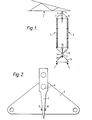
- two electric conductors 1 are suspended from a cross-arm 2 of a pylon by two strings 3 of electric insulators transversely spaced on opposite sides of the centre line of the conductors.
- the strings are connected to a yoke 5 of substantially triangular shape at positions near two of its apices.
- the yoke 5 is pivotally connected at 6 to a pair of elongate energy dissipating members 7 located on opposite sides of the yoke, each member being suspended from the cross-arm 2 by a shackle 4.
- Each elongate energy dissipating member 7 extends along the centre line of the yoke 5 between a pair of restraining stops 8 and, as will be seen clearly in Figure 2, over a part of its length extending between its pivotal axis 6 and the end nearer the restraining stops, is smoothly tapered towards that end.
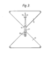
- each insulator string is connected.to a yoke 15 of substantially triangular shape at positions near two of its apices.
- Pivotly mounted at a position 16 near the third or lower of the apices of the yoke 15 are a pair of elongate energy dissipating members 17 located on opposite sides of the yoke.
- the lower ends of the elongate energy dissipating members 17 are secured on opposite sides of a yoke 19 of substantially triangular shape at a position near one of. its apices.
- Each elongate energy dissipating member 17 extends upwardly along the centre line of the yoke 15 and between a pair of restraining stops 18 positioned on opposite sides of the centre line and, as will be seen clearly from Figure 3, the part of each member 17 extending between its pivotal axis 16 and the end of the member nearer the restraining stops is smoothly tapered towards that end.
- the conductors 1 are suspended from the lower apices of the yoke 19.
- the sound insulator string will move transversely to a position in which it is co-linear with the single position of suspension from the cross-arm 2 and as the links 5 and 15 pivot, the parts of the elongate energy dissipating members 7 and 17 extending between the pivotal axes 6, 16 and the ends of the members nearer the restraining stops 8, 18, are gradually and smoothly distorted to an arcuate shape so that the additional load to which the sound insulator string is subjected gradually and smoothly increases from zero to a value such that the resultant load on the sound insulator string does not exceed the maximum safe working load of the string.
Landscapes
- Insulators (AREA)
Applications Claiming Priority (2)
| Application Number | Priority Date | Filing Date | Title |
|---|---|---|---|
| GB8039140 | 1980-12-05 | ||
| GB8039140 | 1980-12-05 |
Publications (2)
| Publication Number | Publication Date |
|---|---|
| EP0055047A2 true EP0055047A2 (de) | 1982-06-30 |
| EP0055047A3 EP0055047A3 (de) | 1982-08-04 |
Family
ID=10517793
Family Applications (1)
| Application Number | Title | Priority Date | Filing Date |
|---|---|---|---|
| EP81305737A Withdrawn EP0055047A3 (de) | 1980-12-05 | 1981-12-04 | Elektrische übertragungsfreileitungen |
Country Status (3)
| Country | Link |
|---|---|
| EP (1) | EP0055047A3 (de) |
| JP (1) | JPS57196821A (de) |
| ZA (1) | ZA818486B (de) |
Cited By (2)
| Publication number | Priority date | Publication date | Assignee | Title |
|---|---|---|---|---|
| CN106571611A (zh) * | 2016-09-26 | 2017-04-19 | 安徽华电工程咨询设计有限公司 | 一种自适应式双挂双联悬垂串 |
| CN115832946A (zh) * | 2022-12-30 | 2023-03-21 | 江西电力职业技术学院 | 绝缘子串挂接装置 |
Families Citing this family (1)
| Publication number | Priority date | Publication date | Assignee | Title |
|---|---|---|---|---|
| ZA824067B (en) * | 1981-06-12 | 1983-04-27 | Balfour Beatty Ltd | Overhead electric transmission lines |
Family Cites Families (2)
| Publication number | Priority date | Publication date | Assignee | Title |
|---|---|---|---|---|
| DE2712979C3 (de) * | 1977-03-24 | 1981-12-10 | Karl Pfisterer Elektrotechnische Spezialartikel Gmbh & Co Kg, 7000 Stuttgart | Vorrichtung zum Aufhängen von Freileitungsseilen an Abspannisolatorketten |
| DE2753544C2 (de) * | 1977-12-01 | 1983-09-15 | Karl Pfisterer Elektrotechnische Spezialartikel Gmbh & Co Kg, 7000 Stuttgart | Vorrichtung zum Anhängen von Freileitungsseilen an eine Mehrfach-Isolatorkette |
-
1981
- 1981-12-04 EP EP81305737A patent/EP0055047A3/de not_active Withdrawn
- 1981-12-05 JP JP56195135A patent/JPS57196821A/ja active Pending
- 1981-12-07 ZA ZA818486A patent/ZA818486B/xx unknown
Cited By (3)
| Publication number | Priority date | Publication date | Assignee | Title |
|---|---|---|---|---|
| CN106571611A (zh) * | 2016-09-26 | 2017-04-19 | 安徽华电工程咨询设计有限公司 | 一种自适应式双挂双联悬垂串 |
| CN106571611B (zh) * | 2016-09-26 | 2018-05-11 | 安徽华电工程咨询设计有限公司 | 一种自适应式双挂双联悬垂串 |
| CN115832946A (zh) * | 2022-12-30 | 2023-03-21 | 江西电力职业技术学院 | 绝缘子串挂接装置 |
Also Published As
| Publication number | Publication date |
|---|---|
| ZA818486B (en) | 1982-10-27 |
| JPS57196821A (en) | 1982-12-02 |
| EP0055047A3 (de) | 1982-08-04 |
Similar Documents
| Publication | Publication Date | Title |
|---|---|---|
| US3002043A (en) | Electrical transmission system | |
| CA3127209C (en) | Transmission line assembly and compact insulator and hardware assembly for a transmission line assembly | |
| US4523054A (en) | Line-past insulator support system, method of assembly thereof, and clamp for use therein | |
| EP0576983B1 (de) | Überspannungsableiteranordnung | |
| US3240870A (en) | Suspension apparatus for bundle conductors | |
| EP0055047A2 (de) | Elektrische übertragungsfreileitungen | |
| US2149875A (en) | Cable support | |
| EP0069485A1 (de) | Elektrisches Übertragungs- oder Verteilungsfreileitungssystem | |
| JP3196971B2 (ja) | 架空送電線懸垂支持装置 | |
| EP0846356A1 (de) | Aufhangungsklammer zur aufhangung von hochspannungskabel an eine tragerstruktur | |
| GB2089142A (en) | Improvements in overhead electric transmission lines | |
| EP0068689B1 (de) | Verbesserungen bei elektrischen Übertragungsfreileitungen | |
| US3443019A (en) | Spacer damper | |
| HUP0303033A2 (en) | Pole top support for aerial electric power lines | |
| US4774622A (en) | Connecting apparatus for lightning arresters for overhead transmission lines | |
| US3264400A (en) | Suppressors for transmission line conductors | |
| JP3115111B2 (ja) | ジャンパ装置及びその装置が取付けられるヨ−ク金具 | |
| DE2816509C2 (de) | Schutzeinrichtung gegen die Folgen eines Isolatorbruches bei Mehrfach-Isolatorenketten | |
| US3250852A (en) | Suspension plate assembly for bundle conductor | |
| GB2101817A (en) | Overhead electric transmission lines | |
| JPH0767236A (ja) | ジャンパー線の横振れ防止装置 | |
| JPH0310571Y2 (de) | ||
| CN215496212U (zh) | 一种重冰区线路用防碰撞双联i型悬垂串 | |
| JP2017184354A (ja) | 架空送電線の引留構造 | |
| CN217469409U (zh) | 一种相间间隔棒 |
Legal Events
| Date | Code | Title | Description |
|---|---|---|---|
| PUAI | Public reference made under article 153(3) epc to a published international application that has entered the european phase |
Free format text: ORIGINAL CODE: 0009012 |
|
| PUAL | Search report despatched |
Free format text: ORIGINAL CODE: 0009013 |
|
| AK | Designated contracting states |
Designated state(s): AT BE CH DE FR IT LU NL SE |
|
| AK | Designated contracting states |
Designated state(s): AT BE CH DE FR IT LU NL SE |
|
| STAA | Information on the status of an ep patent application or granted ep patent |
Free format text: STATUS: THE APPLICATION HAS BEEN WITHDRAWN |
|
| 18W | Application withdrawn |
Withdrawal date: 19830211 |
|
| RIN1 | Information on inventor provided before grant (corrected) |
Inventor name: ADAM, JOHN FRANCIS |