EP0054887A2 - Air flow meter assembly - Google Patents
Air flow meter assembly Download PDFInfo
- Publication number
- EP0054887A2 EP0054887A2 EP81110451A EP81110451A EP0054887A2 EP 0054887 A2 EP0054887 A2 EP 0054887A2 EP 81110451 A EP81110451 A EP 81110451A EP 81110451 A EP81110451 A EP 81110451A EP 0054887 A2 EP0054887 A2 EP 0054887A2
- Authority
- EP
- European Patent Office
- Prior art keywords
- air
- passage
- air flow
- pass
- flow meter
- Prior art date
- Legal status (The legal status is an assumption and is not a legal conclusion. Google has not performed a legal analysis and makes no representation as to the accuracy of the status listed.)
- Granted
Links
Images
Classifications
-
- G—PHYSICS
- G01—MEASURING; TESTING
- G01N—INVESTIGATING OR ANALYSING MATERIALS BY DETERMINING THEIR CHEMICAL OR PHYSICAL PROPERTIES
- G01N15/00—Investigating characteristics of particles; Investigating permeability, pore-volume, or surface-area of porous materials
-
- F—MECHANICAL ENGINEERING; LIGHTING; HEATING; WEAPONS; BLASTING
- F02—COMBUSTION ENGINES; HOT-GAS OR COMBUSTION-PRODUCT ENGINE PLANTS
- F02M—SUPPLYING COMBUSTION ENGINES IN GENERAL WITH COMBUSTIBLE MIXTURES OR CONSTITUENTS THEREOF
- F02M35/00—Combustion-air cleaners, air intakes, intake silencers, or induction systems specially adapted for, or arranged on, internal-combustion engines
- F02M35/02—Air cleaners
- F02M35/0201—Housings; Casings; Frame constructions; Lids; Manufacturing or assembling thereof
- F02M35/021—Arrangements of air flow meters in or on air cleaner housings
-
- F—MECHANICAL ENGINEERING; LIGHTING; HEATING; WEAPONS; BLASTING
- F02—COMBUSTION ENGINES; HOT-GAS OR COMBUSTION-PRODUCT ENGINE PLANTS
- F02D—CONTROLLING COMBUSTION ENGINES
- F02D41/00—Electrical control of supply of combustible mixture or its constituents
- F02D41/02—Circuit arrangements for generating control signals
- F02D41/18—Circuit arrangements for generating control signals by measuring intake air flow
- F02D41/187—Circuit arrangements for generating control signals by measuring intake air flow using a hot wire flow sensor
-
- G—PHYSICS
- G01—MEASURING; TESTING
- G01F—MEASURING VOLUME, VOLUME FLOW, MASS FLOW OR LIQUID LEVEL; METERING BY VOLUME
- G01F1/00—Measuring the volume flow or mass flow of fluid or fluent solid material wherein the fluid passes through a meter in a continuous flow
- G01F1/68—Measuring the volume flow or mass flow of fluid or fluent solid material wherein the fluid passes through a meter in a continuous flow by using thermal effects
- G01F1/684—Structural arrangements; Mounting of elements, e.g. in relation to fluid flow
- G01F1/6842—Structural arrangements; Mounting of elements, e.g. in relation to fluid flow with means for influencing the fluid flow
-
- G—PHYSICS
- G01—MEASURING; TESTING
- G01F—MEASURING VOLUME, VOLUME FLOW, MASS FLOW OR LIQUID LEVEL; METERING BY VOLUME
- G01F5/00—Measuring a proportion of the volume flow
Definitions
- the present invention relates to an air flow meter assembly and, more particularly, to a hot-wire air flow meter assembly suitable for use in a fuel supplying device for internal combustion engines.
- Japanese Patent Laying Open No. 55-37555 discloses an air flow meter having a hot-wire disposed in a by-pass air passage provided in parallel with an air passage leading from an air cleaner and having a venturi portion and a throttle valve through which the air is supplied to the engine.
- An output signal from the hot-wire corresponds to the total air flow supplied to the engine through the air passage, and the output signal is delivered, for example, to a control unit for calculation of the optimum air-fuel ratio of the mixture.
- a fuel injector or a carburetor is controlled in accordance with the optimum air-fuel ratio calculated in the control unit, so that the mixture is fed to the engine at the optimized air-fuel ratio.
- This prior-art air flow meter suffers the following disadvantages. Namely, the air flowing into the air passage through the air cleaner generates vortexes to form complicated stream lines. This turbulency of the air adversely affects the air flowing through the by-pass air passage to cause a disturbance of the output signal from the hot-wire, resulting in an incorrect indication of the air flow.
- the present invention aims as its major object at providing an air flow meter assembly capable of precisely detecting the air flow, while eliminating the above-described problems of the prior art.
- an object of the invention is to provide an air flow meter assembly capable of correctly detecting the air flow without being disturbed by the turbulency of the air flowing into the air passage.
- Another object of the invention is to provide an air flow meter assembly in which the contamination of the detecting means by the carbon and oil particles is avoided to ensure a correct measurement of the air flow.
- an air flow meter assembly comprising: an air passage having a venturi; a first by-pass air passage disposed in parallel with the air passage; and a detecting means disposed in the first by-pass air passage and adapted to generate an output signal corresponding to the air flow passing through the first by-pass air passage, wherein the improvement comprises a cylindrical second air by-pass air passage disposed at the upstream end opening of the first by-pass air passage and adapted to settle the flow of air in the first by-pass air passage.
- the length of the portion of the by-pass air passage upstream from the hot wire is selected to be at least twice as large as the diameter of the first by-pass air passage.
- a cylindrical second by-pass air passage is provided at the upstream end opening of the first by-pass air passage within the area of upper projection of the venturi portion of the air passage, the second by-pass air passage opening along a plane normal to the axis of the venturi portion.
- an air cleaner means 1 is disposed on an air passage 2 provided with a venturi portion 3 formed on the inner peripheral surface at a mid portion thereof. Throttle valves 4, 5 and a fuel injector 6 are secured to the lower portion of the air passage 2. The air induced through the air cleaner means 1 flows through the venturi portion 3 of the air passage 2 and is mixed with the fuel injected by the injector 6 to form an air-fuel mixture which is fed into the cylinders of an internal combustion engine (not shown).
- the flow Q of the air supplied to the engine is detected and the value of which is delivered to a control unit 7 which determines and sets the optimum air-fuel ratio (A/F) of the mixture supplied to the engine.
- the time length of each injection from the injector 6 is determined in accordance with the determined optimum air-fuel ratio (A/F).
- the throttle body including the air passage 2 having the venturi portion 3 is formed by, for example, a die-casting from aluminum, to have a first by-pass air passage 8 formed at a portion thereof near the venturi portion 3.
- the first by-pass air passage 8 has an inlet opening which opens to a land 10 formed at one portion of the air horn 9 on the top of the air passage 2 and an outlet opening communicated with an air passage 2 through a slit 11 formed in the throat portion of the venturi portion 3.
- a pipe or second by-pass air passage 12 made of, for example, a metallic material is secured to the upper portion of the first by-pass air passage 8.
- a heat-sensitive resistor body, i.e. a hot wire 13 is disposed in the first by-pass air passage 8.
- the hot-wire 13 is adapted to change its electric resistance in accordance with the change in the flow of air flowing therearound.
- the hot-wire 13 disposed in the first by-pass air passage is usually composed of two hot-wire elements which constitute two of four sides of a Wheatstone bridge circuit.
- the flow Q A of the air flowing in the air passage 2 of the throttle body is usually determined by the venturi portion 3, and the flow of the air in the first by-pass air passage 8 is changed in proportion to the change in the flow Q A in the air passage 2.
- the hot wire which changes its resistance in response to the change in the flow of air in the first by-pass passage 8, therefore, can generate an output signal proportional to the flow of air supplied to the engine.
- the air stream at the upstream portion of the by-pass air passage tends to be disturbed by, for example, vortexes.
- the present inventors have conducted various experiments to find out the following fact to achieve the present invention. Namely, the unfavourable influence of the turbulency of the air flow appearing in the upstream end portion of the by-pass air passage can be reduced to a negligibly small level by selecting the length t of the portion of the by-pass air passage upstream from the hot-wire 13 to be at least twice, preferably 5 to 10 times, as large as the diameter D of the by-pass air passage.
- the length of the by-pass air passage particularly the length of the portion thereof upstream from the hot-wire, is limited by the size of the throttle body or the construction of the same. It is, therefore, extremely difficult to obtain the desired length of that portion of the by-pass air passage.
- a metallic cylindrical pipe or second by-pass air passage 12 is attached to the upstream inlet portion of the by-pass air passage 8, in order to attain the desired length of the portion of the by-pass air passage upstream from the hot-wire.
- the pipe 12 may be formed from a material other than a metal and can have a cross-sectional shape other than circular. It is, however, desirable that the pipe 12 has an inner bore of a cross-section coinciding with the cross-section of the first by-pass air passage 8 and, preferably, that the cross-sectional area of the inner bore of the pipe 12 coincides with that of the first by-pass air passage 8, in order that the air flow in the by-pass air passage may be not disturbed.
- a honey-comb-like flow settling grid 14 is provided at the upstream side end of the pipe 12 secured to the upstream inlet portion of the first by-pass air passage 8. This flow settling grid 14 effectively settles further the stream of air flowing in the by-pass air passage.
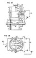
- Figs. 3A and 3B show another embodiment of the invention. More specifically, Fig. 3A is a sectional view taken along the two-dots-and-dash line A-A of Fig. 3B.
- a throttle valve 15 is mounted on a rotary shaft 16 disposed at the downstream side of the air passage 2, and acts to control the air flow supply to the engine.
- a pipe or second by-pass air passage 20 bent at a predetermined curvature is attached to the upstream inlet portion of the first by-pass air passage 8.
- This pipe is made of, for example, a metal and has a flange member 21 attached thereto by means of welding or the like measure.
- the pipe 20 having the flange 21 is firmly fixed to the land 10 of the throttle body by means of screws 22.
- a supporting member 23 of, for example, a metal is secured to the same land portion by means of screws 24 to be in support of the bent pipe 20.
- the bent pipe 20 has an inlet opening residing in the area of the upper projection of the venturi portion 3 and exists in the plane substantially perpendicular to the axis of the venturi portion 3.
- the inlet opening of the pipe 20 opens on a straight line substantially perpendicular to the axis of the venturi portion 3.
- the invention it is possible to stabilize the flow of air in the by-pass air passage, particularly in the region around the hot-wire to achieve a stable heat transfer between the hot-wire and the air flowing therearound, so that the air flow can be detected at a high precision.
Abstract
Description
- The present invention relates to an air flow meter assembly and, more particularly, to a hot-wire air flow meter assembly suitable for use in a fuel supplying device for internal combustion engines.
- Hitherto, there have been proposed various types of air flow meters for internal combustion engines. For instance, Japanese Patent Laying Open No. 55-37555 (March 15, 1980) discloses an air flow meter having a hot-wire disposed in a by-pass air passage provided in parallel with an air passage leading from an air cleaner and having a venturi portion and a throttle valve through which the air is supplied to the engine. An output signal from the hot-wire corresponds to the total air flow supplied to the engine through the air passage, and the output signal is delivered, for example, to a control unit for calculation of the optimum air-fuel ratio of the mixture. A fuel injector or a carburetor is controlled in accordance with the optimum air-fuel ratio calculated in the control unit, so that the mixture is fed to the engine at the optimized air-fuel ratio.
- This prior-art air flow meter, however, suffers the following disadvantages. Namely, the air flowing into the air passage through the air cleaner generates vortexes to form complicated stream lines. This turbulency of the air adversely affects the air flowing through the by-pass air passage to cause a disturbance of the output signal from the hot-wire, resulting in an incorrect indication of the air flow.
- In addition, it is often experienced that contaminants such as carbon particles, oil particles and so forth come into the by-pass passage due to the phenomenon peculiar in engines such as back-fire. These contaminants undesirably attach to the surface of the hot-wire to deteriorate the sensitivity of the latter.
- Accordingly, the present invention aims as its major object at providing an air flow meter assembly capable of precisely detecting the air flow, while eliminating the above-described problems of the prior art.
- Namely, an object of the invention is to provide an air flow meter assembly capable of correctly detecting the air flow without being disturbed by the turbulency of the air flowing into the air passage.
- Another object of the invention is to provide an air flow meter assembly in which the contamination of the detecting means by the carbon and oil particles is avoided to ensure a correct measurement of the air flow.
- To these ends, according to the invention, there is provided an air flow meter assembly comprising: an air passage having a venturi; a first by-pass air passage disposed in parallel with the air passage; and a detecting means disposed in the first by-pass air passage and adapted to generate an output signal corresponding to the air flow passing through the first by-pass air passage, wherein the improvement comprises a cylindrical second air by-pass air passage disposed at the upstream end opening of the first by-pass air passage and adapted to settle the flow of air in the first by-pass air passage.
- According to an embodiment of the invention, the length of the portion of the by-pass air passage upstream from the hot wire is selected to be at least twice as large as the diameter of the first by-pass air passage.
- According to another embodiment of the invention, a cylindrical second by-pass air passage is provided at the upstream end opening of the first by-pass air passage within the area of upper projection of the venturi portion of the air passage, the second by-pass air passage opening along a plane normal to the axis of the venturi portion.
- The above and other objects, as well as advantageous features of the invention will become clear from the following description of the preferred embodiments taken in conjunction with the accompanying drawings.
-
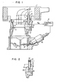
- Fig. 1 is a sectional view of a hot-wire air flow meter assembly constructed in accordance with an embodiment of the present invention;
- Fig. 2 is a sectional view of a modification of a pipe incorporated in the hot-wire air flow meter assembly as shown in Fig. 1; and
- Figs. 3A and 3B are a sectional view and a top plan view of a hot-wire air flow meter assembly constructed in accordance with another embodiment of the present invention.
- Referring first to Fig. 1, an air cleaner means 1 is disposed on an
air passage 2 provided with aventuri portion 3 formed on the inner peripheral surface at a mid portion thereof. Throttle valves 4, 5 and a fuel injector 6 are secured to the lower portion of theair passage 2. The air induced through the air cleaner means 1 flows through theventuri portion 3 of theair passage 2 and is mixed with the fuel injected by the injector 6 to form an air-fuel mixture which is fed into the cylinders of an internal combustion engine (not shown). - As is well known, the flow Q of the air supplied to the engine is detected and the value of which is delivered to a control unit 7 which determines and sets the optimum air-fuel ratio (A/F) of the mixture supplied to the engine. The time length of each injection from the injector 6 is determined in accordance with the determined optimum air-fuel ratio (A/F).
- The throttle body including the
air passage 2 having theventuri portion 3 is formed by, for example, a die-casting from aluminum, to have a first by-pass air passage 8 formed at a portion thereof near theventuri portion 3. The first by-pass air passage 8 has an inlet opening which opens to aland 10 formed at one portion of theair horn 9 on the top of theair passage 2 and an outlet opening communicated with anair passage 2 through a slit 11 formed in the throat portion of theventuri portion 3. A pipe or second by-pass air passage 12 made of, for example, a metallic material is secured to the upper portion of the first by-pass air passage 8. A heat-sensitive resistor body, i.e. ahot wire 13, is disposed in the first by-pass air passage 8. The hot-wire 13 is adapted to change its electric resistance in accordance with the change in the flow of air flowing therearound. - Although not shown, the hot-
wire 13 disposed in the first by-pass air passage is usually composed of two hot-wire elements which constitute two of four sides of a Wheatstone bridge circuit. - The flow QA of the air flowing in the
air passage 2 of the throttle body is usually determined by theventuri portion 3, and the flow of the air in the first by-pass air passage 8 is changed in proportion to the change in the flow QA in theair passage 2. The hot wire which changes its resistance in response to the change in the flow of air in the first by-pass passage 8, therefore, can generate an output signal proportional to the flow of air supplied to the engine. - In general, in the air flow meter assembly having a by-pass air passage formed in parallel with an air passage, the air stream at the upstream portion of the by-pass air passage tends to be disturbed by, for example, vortexes.
- The present inventors have conducted various experiments to find out the following fact to achieve the present invention. Namely, the unfavourable influence of the turbulency of the air flow appearing in the upstream end portion of the by-pass air passage can be reduced to a negligibly small level by selecting the length t of the portion of the by-pass air passage upstream from the hot-
wire 13 to be at least twice, preferably 5 to 10 times, as large as the diameter D of the by-pass air passage. On the other hand, the length of the by-pass air passage, particularly the length of the portion thereof upstream from the hot-wire, is limited by the size of the throttle body or the construction of the same. It is, therefore, extremely difficult to obtain the desired length of that portion of the by-pass air passage. - In the embodiment described above, therefore, a metallic cylindrical pipe or second by-
pass air passage 12 is attached to the upstream inlet portion of the by-pass air passage 8, in order to attain the desired length of the portion of the by-pass air passage upstream from the hot-wire. Thepipe 12, however, may be formed from a material other than a metal and can have a cross-sectional shape other than circular. It is, however, desirable that thepipe 12 has an inner bore of a cross-section coinciding with the cross-section of the first by-pass air passage 8 and, preferably, that the cross-sectional area of the inner bore of thepipe 12 coincides with that of the first by-pass air passage 8, in order that the air flow in the by-pass air passage may be not disturbed. - Referring to Fig. 2, a honey-comb-like flow settling grid 14 is provided at the upstream side end of the
pipe 12 secured to the upstream inlet portion of the first by-pass air passage 8. This flow settling grid 14 effectively settles further the stream of air flowing in the by-pass air passage. - Figs. 3A and 3B show another embodiment of the invention. More specifically, Fig. 3A is a sectional view taken along the two-dots-and-dash line A-A of Fig. 3B. In these Figures, the same reference numerals are used to denote the same parts or members as those in the first embodiment shown in Fig. 1. In the hot-wire air flow meter assembly of the invention shown in Figs. 3A and 3B, a
throttle valve 15 is mounted on arotary shaft 16 disposed at the downstream side of theair passage 2, and acts to control the air flow supply to the engine. A fuel injector or a carburetor of the same type as that shown in Fig. 1 secured to the lower portion of the throttle body having thethrottle valve 15. - As will be seen from Figs. 3A, 3B, a pipe or second by-
pass air passage 20 bent at a predetermined curvature is attached to the upstream inlet portion of the first by-pass air passage 8. This pipe is made of, for example, a metal and has aflange member 21 attached thereto by means of welding or the like measure. Thepipe 20 having theflange 21 is firmly fixed to theland 10 of the throttle body by means ofscrews 22. Furthermore, a supportingmember 23 of, for example, a metal is secured to the same land portion by means ofscrews 24 to be in support of thebent pipe 20. - As will be seen from these Figures, the
bent pipe 20 has an inlet opening residing in the area of the upper projection of theventuri portion 3 and exists in the plane substantially perpendicular to the axis of theventuri portion 3. - In still another embodiment, the inlet opening of the
pipe 20 opens on a straight line substantially perpendicular to the axis of theventuri portion 3. - Due to the bending of the
pipe 20, carbon and oil particles having comparatively large inertia can hardly be introduced into thepipe 20, while the air having comparatively small inertia is allowed to easily come into thepipe 20. In consequence, the attaching of carbon and oil particles to the hot-wire 13, attributable to the back-fire and other phenomenon, can fairly be avoided to ensure a correct measuring of the air flow. The change in the resistance of the hot-wire 13 is detected by a detectingmeans 25 and is sent to the control unit. - According to the invention, it is possible to stabilize the flow of air in the by-pass air passage, particularly in the region around the hot-wire to achieve a stable heat transfer between the hot-wire and the air flowing therearound, so that the air flow can be detected at a high precision. In addition, it is possible to eliminate unfavourable effect of carbon and oil particles on the measurement of the air flow.
Claims (10)
Applications Claiming Priority (2)
| Application Number | Priority Date | Filing Date | Title |
|---|---|---|---|
| JP55182272A JPS57104817A (en) | 1980-12-22 | 1980-12-22 | Air quantity measuring apparatus for internal combustion engine |
| JP182272/80 | 1980-12-22 |
Publications (3)
| Publication Number | Publication Date |
|---|---|
| EP0054887A2 true EP0054887A2 (en) | 1982-06-30 |
| EP0054887A3 EP0054887A3 (en) | 1983-10-05 |
| EP0054887B1 EP0054887B1 (en) | 1988-03-02 |
Family
ID=16115357
Family Applications (1)
| Application Number | Title | Priority Date | Filing Date |
|---|---|---|---|
| EP81110451A Expired EP0054887B1 (en) | 1980-12-22 | 1981-12-15 | Air flow meter assembly |
Country Status (5)
| Country | Link |
|---|---|
| US (1) | US4495802A (en) |
| EP (1) | EP0054887B1 (en) |
| JP (1) | JPS57104817A (en) |
| KR (1) | KR880000356B1 (en) |
| DE (1) | DE3176670D1 (en) |
Cited By (5)
| Publication number | Priority date | Publication date | Assignee | Title |
|---|---|---|---|---|
| US4982602A (en) * | 1989-02-24 | 1991-01-08 | Robert Bosch Gmbh | Air metering device |
| DE3922488A1 (en) * | 1989-07-08 | 1991-01-17 | Bosch Gmbh Robert | AIR MEASURING DEVICE |
| EP0801224A2 (en) * | 1992-08-31 | 1997-10-15 | Hitachi, Ltd. | Air intake arrangement for internal combustion engine |
| GB2328514A (en) * | 1997-08-16 | 1999-02-24 | Bosch Gmbh Robert | Air filter unit including a tube to protect a flow meter |
| USRE37269E1 (en) | 1992-08-31 | 2001-07-10 | Hitachi, Ltd. | Air intake arrangement for internal combustion engine |
Families Citing this family (12)
| Publication number | Priority date | Publication date | Assignee | Title |
|---|---|---|---|---|
| JPS58111720A (en) * | 1981-12-25 | 1983-07-02 | Japan Electronic Control Syst Co Ltd | Air intake structure of internal combustion engine |
| JPS60107525A (en) * | 1983-11-16 | 1985-06-13 | Hitachi Ltd | Hot wire type air flow meter |
| US4674460A (en) * | 1985-09-30 | 1987-06-23 | Chrysler Motors Corporation | Fuel injection system |
| DE3539013A1 (en) * | 1985-11-02 | 1987-05-07 | Vdo Schindling | ARRAY MEASURING ARRANGEMENT FOR AN INTERNAL COMBUSTION ENGINE |
| US4942763A (en) * | 1988-03-23 | 1990-07-24 | Harpster Joseph W | Flow sensor assembly |
| JPH0654251B2 (en) * | 1988-10-18 | 1994-07-20 | 株式会社日立製作所 | Air flow meter for internal combustion engine |
| KR950001326B1 (en) * | 1990-03-12 | 1995-02-17 | 가부시기가이샤 히다찌 세이사꾸쇼 | Air flow meter for internal combustion engines and manufacturing method thereof |
| US5537870A (en) * | 1994-10-03 | 1996-07-23 | Ford Motor Company | Contaminant free backflow reducing insert for mass air flow sensors |
| US6142123A (en) * | 1998-12-14 | 2000-11-07 | Cannondale Corporation | Motorcycle |
| JP4629909B2 (en) * | 2001-05-23 | 2011-02-09 | ヤンマー株式会社 | Rice transplanter planting department |
| JP5785717B2 (en) | 2011-01-14 | 2015-09-30 | 本田技研工業株式会社 | Intake device for internal combustion engine |
| US9115671B2 (en) * | 2012-11-07 | 2015-08-25 | Benebe, Inc. | Hybrid carburetor and fuel injection assembly for an internal combustion engine |
Citations (5)
| Publication number | Priority date | Publication date | Assignee | Title |
|---|---|---|---|---|
| DE2914275A1 (en) * | 1978-04-10 | 1979-10-18 | Hitachi Ltd | AIR FLOW MEASURING DEVICE |
| DE2921787A1 (en) * | 1978-06-02 | 1979-12-06 | Hitachi Ltd | AIR FLOW METER |
| GB2025062A (en) * | 1978-06-24 | 1980-01-16 | Degussa | Hot-wire Anemometer |
| JPS5578164A (en) * | 1978-12-06 | 1980-06-12 | Hitachi Ltd | Air/fuel mixture supply device |
| JPS55119925A (en) * | 1979-03-07 | 1980-09-16 | Hitachi Ltd | Hot-wire type air-flow meter for internal combustion engine |
Family Cites Families (5)
| Publication number | Priority date | Publication date | Assignee | Title |
|---|---|---|---|---|
| JPS54106720A (en) * | 1978-02-10 | 1979-08-22 | Mitsubishi Electric Corp | Measuring apparatus for flow rate sucked air in internal combustion engine |
| JPS591347B2 (en) * | 1978-06-28 | 1984-01-11 | 株式会社日立製作所 | fuel supply device |
| JPS5537555A (en) * | 1978-09-11 | 1980-03-15 | Hitachi Ltd | Air fuel ratio controller |
| JPS5676012A (en) * | 1979-11-27 | 1981-06-23 | Hitachi Ltd | Measuring device of suction air quantity |
| JPS5677716A (en) * | 1979-11-29 | 1981-06-26 | Hitachi Ltd | Detector for amount of sucked air |
-
1980
- 1980-12-22 JP JP55182272A patent/JPS57104817A/en active Pending
-
1981
- 1981-12-10 KR KR1019810004842A patent/KR880000356B1/en active
- 1981-12-15 EP EP81110451A patent/EP0054887B1/en not_active Expired
- 1981-12-15 DE DE8181110451T patent/DE3176670D1/en not_active Expired
-
1984
- 1984-02-29 US US06/584,896 patent/US4495802A/en not_active Expired - Lifetime
Patent Citations (5)
| Publication number | Priority date | Publication date | Assignee | Title |
|---|---|---|---|---|
| DE2914275A1 (en) * | 1978-04-10 | 1979-10-18 | Hitachi Ltd | AIR FLOW MEASURING DEVICE |
| DE2921787A1 (en) * | 1978-06-02 | 1979-12-06 | Hitachi Ltd | AIR FLOW METER |
| GB2025062A (en) * | 1978-06-24 | 1980-01-16 | Degussa | Hot-wire Anemometer |
| JPS5578164A (en) * | 1978-12-06 | 1980-06-12 | Hitachi Ltd | Air/fuel mixture supply device |
| JPS55119925A (en) * | 1979-03-07 | 1980-09-16 | Hitachi Ltd | Hot-wire type air-flow meter for internal combustion engine |
Non-Patent Citations (2)
| Title |
|---|
| Patent Abstracts of Japan vol. 4, no. 120, 26 August 1980 page 147M28 & JP-A-55 078 164 * |
| Patent Abstracts of Japan vol. 4, no. 169, 21 November 1980 & JP-A-55 119 925 * |
Cited By (8)
| Publication number | Priority date | Publication date | Assignee | Title |
|---|---|---|---|---|
| US4982602A (en) * | 1989-02-24 | 1991-01-08 | Robert Bosch Gmbh | Air metering device |
| DE3922488A1 (en) * | 1989-07-08 | 1991-01-17 | Bosch Gmbh Robert | AIR MEASURING DEVICE |
| US5119672A (en) * | 1989-07-08 | 1992-06-09 | Robert Bosch Gmbh | Air flow rate meter |
| EP0801224A2 (en) * | 1992-08-31 | 1997-10-15 | Hitachi, Ltd. | Air intake arrangement for internal combustion engine |
| EP0801224A3 (en) * | 1992-08-31 | 1998-04-15 | Hitachi, Ltd. | Air intake arrangement for internal combustion engine |
| USRE37269E1 (en) | 1992-08-31 | 2001-07-10 | Hitachi, Ltd. | Air intake arrangement for internal combustion engine |
| GB2328514A (en) * | 1997-08-16 | 1999-02-24 | Bosch Gmbh Robert | Air filter unit including a tube to protect a flow meter |
| GB2328514B (en) * | 1997-08-16 | 1999-07-21 | Bosch Gmbh Robert | Filter unit |
Also Published As
| Publication number | Publication date |
|---|---|
| US4495802A (en) | 1985-01-29 |
| JPS57104817A (en) | 1982-06-30 |
| DE3176670D1 (en) | 1988-04-07 |
| EP0054887A3 (en) | 1983-10-05 |
| EP0054887B1 (en) | 1988-03-02 |
| KR880000356B1 (en) | 1988-03-20 |
| KR830008155A (en) | 1983-11-16 |
Similar Documents
| Publication | Publication Date | Title |
|---|---|---|
| EP0054887A2 (en) | Air flow meter assembly | |
| US6240775B1 (en) | Flow rate sensor | |
| EP0322459B1 (en) | Hot wire type air flow meter | |
| US4991560A (en) | Hot-wire air flow meter and internal combustion engine provided with same | |
| EP0023970A2 (en) | Air flow meter | |
| US4395907A (en) | Air flow rate measuring device | |
| DE4410049C2 (en) | Air mass flow sensor assembly | |
| KR940000704Y1 (en) | Turbulence flow meter | |
| KR900001464B1 (en) | Hot wire type air flow meter | |
| US4922879A (en) | Intake arrangement for internal combustion engine | |
| EP0085987B1 (en) | Fuel feeding apparatus for internal combustion engine | |
| JPS6120499Y2 (en) | ||
| JPH0258571B2 (en) | ||
| US4986116A (en) | Air flow meter for internal combustion engine | |
| JP2993912B2 (en) | Air flow meter and internal combustion engine using it | |
| JP3058704B2 (en) | Throttle body | |
| JPS5942808B2 (en) | flow measuring device | |
| JP2804188B2 (en) | Throttle body | |
| JPH089612Y2 (en) | Intake air flow rate measuring device for internal combustion engine | |
| JPH0346199Y2 (en) | ||
| JPH0454891B2 (en) | ||
| JPH0337687B2 (en) | ||
| JPS5810612A (en) | Suction air flowmeter employing constant temperature difference heat generating resistor | |
| JPH0151131B2 (en) | ||
| JPS6253060B2 (en) |
Legal Events
| Date | Code | Title | Description |
|---|---|---|---|
| PUAI | Public reference made under article 153(3) epc to a published international application that has entered the european phase |
Free format text: ORIGINAL CODE: 0009012 |
|
| AK | Designated contracting states |
Designated state(s): BE CH DE FR GB IT NL SE |
|
| PUAL | Search report despatched |
Free format text: ORIGINAL CODE: 0009013 |
|
| AK | Designated contracting states |
Designated state(s): BE CH DE FR GB IT LI NL SE |
|
| 17P | Request for examination filed |
Effective date: 19831006 |
|
| GRAA | (expected) grant |
Free format text: ORIGINAL CODE: 0009210 |
|
| AK | Designated contracting states |
Kind code of ref document: B1 Designated state(s): DE FR GB |
|
| REF | Corresponds to: |
Ref document number: 3176670 Country of ref document: DE Date of ref document: 19880407 |
|
| ET | Fr: translation filed | ||
| PLBE | No opposition filed within time limit |
Free format text: ORIGINAL CODE: 0009261 |
|
| STAA | Information on the status of an ep patent application or granted ep patent |
Free format text: STATUS: NO OPPOSITION FILED WITHIN TIME LIMIT |
|
| 26N | No opposition filed | ||
| PGFP | Annual fee paid to national office [announced via postgrant information from national office to epo] |
Ref country code: FR Payment date: 19911018 Year of fee payment: 11 |
|
| PGFP | Annual fee paid to national office [announced via postgrant information from national office to epo] |
Ref country code: GB Payment date: 19911205 Year of fee payment: 11 |
|
| PG25 | Lapsed in a contracting state [announced via postgrant information from national office to epo] |
Ref country code: GB Effective date: 19921215 |
|
| GBPC | Gb: european patent ceased through non-payment of renewal fee |
Effective date: 19921215 |
|
| PG25 | Lapsed in a contracting state [announced via postgrant information from national office to epo] |
Ref country code: FR Effective date: 19930831 |
|
| REG | Reference to a national code |
Ref country code: FR Ref legal event code: ST |
|
| PGFP | Annual fee paid to national office [announced via postgrant information from national office to epo] |
Ref country code: DE Payment date: 20001229 Year of fee payment: 20 |