EP0054617A1 - Paliers magnétiques linéaires - Google Patents
Paliers magnétiques linéaires Download PDFInfo
- Publication number
- EP0054617A1 EP0054617A1 EP19810107072 EP81107072A EP0054617A1 EP 0054617 A1 EP0054617 A1 EP 0054617A1 EP 19810107072 EP19810107072 EP 19810107072 EP 81107072 A EP81107072 A EP 81107072A EP 0054617 A1 EP0054617 A1 EP 0054617A1
- Authority
- EP
- European Patent Office
- Prior art keywords
- electromagnets
- linear member
- housing means
- housing
- diamagnetic
- Prior art date
- Legal status (The legal status is an assumption and is not a legal conclusion. Google has not performed a legal analysis and makes no representation as to the accuracy of the status listed.)
- Granted
Links
Images


Classifications
-
- F—MECHANICAL ENGINEERING; LIGHTING; HEATING; WEAPONS; BLASTING
- F16—ENGINEERING ELEMENTS AND UNITS; GENERAL MEASURES FOR PRODUCING AND MAINTAINING EFFECTIVE FUNCTIONING OF MACHINES OR INSTALLATIONS; THERMAL INSULATION IN GENERAL
- F16C—SHAFTS; FLEXIBLE SHAFTS; ELEMENTS OR CRANKSHAFT MECHANISMS; ROTARY BODIES OTHER THAN GEARING ELEMENTS; BEARINGS
- F16C29/00—Bearings for parts moving only linearly
-
- F—MECHANICAL ENGINEERING; LIGHTING; HEATING; WEAPONS; BLASTING
- F16—ENGINEERING ELEMENTS AND UNITS; GENERAL MEASURES FOR PRODUCING AND MAINTAINING EFFECTIVE FUNCTIONING OF MACHINES OR INSTALLATIONS; THERMAL INSULATION IN GENERAL
- F16C—SHAFTS; FLEXIBLE SHAFTS; ELEMENTS OR CRANKSHAFT MECHANISMS; ROTARY BODIES OTHER THAN GEARING ELEMENTS; BEARINGS
- F16C32/00—Bearings not otherwise provided for
- F16C32/04—Bearings not otherwise provided for using magnetic or electric supporting means
- F16C32/0406—Magnetic bearings
- F16C32/044—Active magnetic bearings
- F16C32/0444—Details of devices to control the actuation of the electromagnets
-
- F—MECHANICAL ENGINEERING; LIGHTING; HEATING; WEAPONS; BLASTING
- F16—ENGINEERING ELEMENTS AND UNITS; GENERAL MEASURES FOR PRODUCING AND MAINTAINING EFFECTIVE FUNCTIONING OF MACHINES OR INSTALLATIONS; THERMAL INSULATION IN GENERAL
- F16C—SHAFTS; FLEXIBLE SHAFTS; ELEMENTS OR CRANKSHAFT MECHANISMS; ROTARY BODIES OTHER THAN GEARING ELEMENTS; BEARINGS
- F16C32/00—Bearings not otherwise provided for
- F16C32/04—Bearings not otherwise provided for using magnetic or electric supporting means
- F16C32/0406—Magnetic bearings
- F16C32/044—Active magnetic bearings
- F16C32/0472—Active magnetic bearings for linear movement
Definitions
- the invention relates to a self-regulating active magnetic bearing.
- the invention has particula-r-utility in providing radial support of a linear shaft magnetically without physical contact, while permitting it to freely translate and/or rotate, thus eliminating frictional wear which eliminates the need for lubricants and thereby guarantees a relatively long operational life.
- Such apparatus is vitally necessary in applications where the equipment becomes substantially inaccessible once put into operation..
- a magnetic bearing is a device which includes a relatively stationary electromagnetic circuit which.is adapted to hold a magnetizable element in suspension.
- An active magnetic bearing includes a displacement detector and an electronic control unit coupled thereto which forms a servosystem whereby any displacement of the suspended element as sensed by the detector is counteracted by an opposing magnetic force generated by the electromagnetic circuit in response to an output from the electronic control unit. While such apparatus is well known, it nevertheless is still subject to various physical phenomenon of non-mechanical origin such as eddy current losses, undesired phase shifts, etc. which have a deleterious effect on the operation and efficiency of the system.
- an object of the invention to provide an improved, linear, non-frictional magnetic bearing having an elongated housing for containing a shaft type armature with quadrature positioned shaft position sensors and equidistantly positioned electromagnets located at each end of the housing.
- Each set of sensors is responsive to orthogonal displacement of the armature and is utilized to generate control signals to energize the electromagnets to center the armature.
- a bumper magnet assembly is located at one end of the housing for dampening any undesired axial movement of the armature.
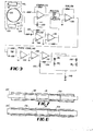
- FIG. 1 shown therein are two sets of four stationary electromagnets 10 1 , 12 1 , 14 1 , 16 1 and 102, 12 2 , 14 2 , 1 6 2 located at each end of an elongated cylindrical housing 18 comprised of diamagnetic, i.e., non-nagnetic, material which is adapted to accommodate an armature 20 in the form of a linear cylindrical shaft.
- the armature shaft 20 is adapted for both reciprocal and rotational motion within the housing 18.
- the shaft 20 is paramagnetic, i.e., highly magnetic, at least in the vicinity of two sets of pole pieces 22 1 , 24 1 , 26 1 , 28 1 , and 22 2 , 24 2 , 26 2 , 28 2 so that the flux generated by respective coils 32 1 , 34 1 , 3 6 1 , 3 8 1 , and 32 2 , 34 2 , 36 2 , 38 2 are circulated through two housing wall sections 39 1 and 39 2 , respectively, in a closed path 30 through two series air gaps 40 1 , 42 1 and 40 2 , 42 2 respectively, formed between the outer surface 43 of the shaft 20 and the pole piece faces 44 1 , 46 1 and 44 2 462.
- a magnetic attraction force is developed by each of the electromagnets in the respective pole pieces by applying a unidirectional (DC) current to the coils 32 1 , 34 1 ...36 2 , 38 2 .
- DC unidirectional
- the system shown in Figure 1 is an active system in that positional information with respect to axial alignment of the shaft 20 is provided to excite opposing pairs of coils e.g., 32 1 and 36 1 by means of one of four like feedback control loops, to be described, with reference to .
- Figure 9 The positional information at each end of the housing 18 is provided by two pairs of sensor devices which include transducers 48 1 , 50 1 and 48 2 , 50 2 . These transducers are placed at right angles to one another, aligned with and adjacent respective electromagnets 10 1 , 12 1 and 10 2 , 12 2 .
- the transducers may consist of eddy current sensor devices which include a probe tip, not shown, which extends into the interior of the housing 18 in close proximity to the outer surface 43 of the armature shaft 20.
- This type of sensor device is of a conventional design and comprises one component of a known eddy current sensor system, a typical example of which is a Probe Tip Model No. 300 marketed by the Bently Nevada Corporation.
- capacitive-type sensors may be employed.
- Position sensor 48 1 for example, is adapted to operate in conjunction with the electromagnets 10 1 and 14 1 which lie along one rectilinear axis whereas position sensor 50 1 operates in connection with electromagnets 12 1 and 16 1 , which lie along an axis perpendicular to the first axis.
- FIG. 2 the housing 18 is shown in cross section mounted between two support pedestals 52 and 54 which are secured to the base plate member 56.
- the two sets of electromagnets 10 1 , 10 2 , etc. are mounted on the housing 18 by two tubular type outer flange members 58 and 60, respectively, and a central flange member 62 which is also tubular in shape.
- the respective flange members include right angled circular flange sections 64, 66, 68 and 70 which are adapted to accept threaded hardware for securing the respective pole pieces thereto.
- the outer flange members 58 and 60 are securely fastened to the housing 18 and additionally include respective outwardly extending shield plates 72 and 74 which shield the position transducers 48 1 , 50 1 and 48 2 , 50 2 from the respective electromagnets which are located on the other side thereof.
- each transducer 48 1 , 48 1 , 48 2 , etc. includes a threaded outer wall which is adapted to engage and be held in place by nuts 80, 82 which also provide for positioning the tip of the transducers 48 1 and 48 2 within the holes 84 1 and 84 2 provided in the wall of the housing 18.
- the same structure is utilized for the orthogonally positioned transducers 50 1 and 50 2 shown in Figure 1.
- the armature shaft 20 includes enlarged cross sectional portions 86 and 88 in the region of the pole pieces 22 1 , 26 1 and 22 2 , 26 2 , respectively.
- the armature shaft 20, moreover, is comprised of magnetically permeable (paramagnetic) material throughout and accordingly the enlarged portions 86 and 88 provide a close magnetic coupling to the surrounding pole pieces.
- the cross sectional area of the shaft portions 86 and 88 is also made sufficiently large not to saturate; otherwise, a substantial amount of coil ampere turns would be required for the passage of the armature flux.
- the shaft material is typically comprised of cold rolled steel because it has a relatively high magnetic saturation level and as such a relatively'small diameter shaft can pass a large amount of flux. Its relatively low permeability also gives a larger AC skin depth for AC flux penetration than, for example, pure iron.
- FIG. 1 While the orthogonality of the electromagnets is shown in Figure 1, it is further illustrated in Figure 3 wherein electromagnets 10 1 and 14 1 are shown opposing one another along the vertical axis while electromagnets 12 1 and 16 1 oppose one another along the horizontal axis.
- Figure 3 also illustrates .the central longitudinal alignment of the shaft portion 86 within the housing 18 when suspended as well as the general shape of the pole pieces 2 2 1 , 24 1 , 26 1 and 28 1 , and their respective windings 32 1 , 34 1 , 36 1 and 38 1 .
- pole piece 22 1 is shown in perspective view in Figure 4.
- the pole piece 22 1 is a generally U-shaped, bifurcated member including leg portions 90 and 92 separated by a bight portion 93.
- the leg portions 90 and 92 are tapered downwardly toward concave pole faces 94 and 96, respectively, which have a radius just slightly larger than the inner surface of the housing 18.
- the tapering of the pole piece leg portions 90 and 92 provides a concentration of the flux whereas the curved pole faces 94 and 96 provide a constant air gap between the pole piece and the suspended shaft 40 and 42 as shown in Figures 1 and 3.
- the pole piece mid-section or bight portion 93 which accommodates a coil, not shown, and is relatively thick in the region 98 to avoid saturation and allow the flux to pass at a low flux density level through the pole faces 94 and 96 to the armature shaft 20.
- the tapered pole piece also serves to increase the magnetic suspension force of the bearing .inasmuch as the suspension force is proportional to the square of the flux divided by the gap cross sectional area. Accordingly, the smaller the cross sectional area of the gap, the greater the attractive force.
- the pole pieces need not be tapered, however, to work effectively.
- the armature shaft 20 shown in the preferred embodiment of Figure 2, is comprised of a unitary member, it nevertheless includes a small diameter axial bore 85 which terminates in enlarged diameter end bore portions 87 and 89 which exist in the region of the position transducers 48 1 , 50 1 and 48 2 , 50 2 , respectively.
- the purpose of the bore portions 85, 87 and 89 is to reduce the weight of the suspended shaft as much as possible. Accordingly, the diameter of the shaft 20 is further reduced in the intermediate region 91 shown in Figure 2.
- FIG. 7 Alternative configurations of the armature shaft 20 are shown in Figures 7 and 8.
- a relatively small diameter shaft member 20' which may be hollow, for example, includes a pair of paramagnetic sleeve members 98 and 100 fitted on the outer surface of the shaft in the region of the electromagnets, not shown.
- the shaft 20' need not be comprised of magnetically permeable material but may consist of diamagnetic material, such as plastic.
- FIG. 8 another configuration of the armature shaft comprises the configuration shown in Figure 8 wherein reference numeral 20" denotes a relatively thin hollow tubular shaft consisting of paramagnetic material within which is placed a pair of internal sleeve members 102 and 104, also comprised of paramagnetic material. In both cases the region of the location of the electromagnets in the respective air gaps is enlarged so that magnetic saturation does not occur with the design of the particular magnetic circuit utilized.
- Figures 5 and 6 respectively provide a side planar and end view of a schematic representation of the invention.
- the armature shaft 20 is centrally located between the pole pieces 22 I , 24 1P 26 1 and 28 1 .
- flux paths 30 1 and 30 2 respectively, cross the air gaps 40 1 , 42 1 and 40 2 , 42 2 to the surface of the armature shaft 20 whereupon a magnetic attraction force is developed by each individual pole piece when a DC current is applied to the respective coils.
- the applied force F produces a cantilever effect on the shaft 20 which results in different forces being applied about the respective X-Y axes at the location of the two sets of electromagnets. Therefore, counter moments must be separately created by the eight pole pieces which also results in the bearing having an enhanced torsional stability and moment carrying capability.
- each coil can be energized in response to shaft position information derived by one of the transducers 48 1 , 50 1 or 48 2 , 50 2 which are also located along the X-Y axes. While a minimum number of electromagnets required to constrain a shaft is three, a three pole configuration requires complex signal processing to direct current through the appropriate suspension coils. A four pole configuration therefore provides a simpler approach because coil excitation signals for only two axes (X and Y) are required.
- an axially magnetized bumper assembly 106 which is secured to a shaft 110 attached to one end of the shaft 20.
- the shaft 110 extends through one of a pair of stationary axially magnetized permanent magnets 112 and 114 which are held in place by a cylindrical housing 116 attached to the pedestal 52.
- the magnet 108 is poled to be repulsed by both of the stationary magnets 112 and 114 so that it is adapted to float therebetween.
- any undesired lateral, i.e., axial, displacement of the armature shaft 20 will be acted on by a restoring force developed by the assembly 106.
- a coil 118 is provided around the housing 116 which is excited by an AC current.
- an axial magnetic field will be applied to the bumper magnet 108 which will oscillate back and forth between the fixed magnets 112 and 114. Because it is attached to the armature shaft 20 by means of the rod 110, an oscillatory movement will be imparted to the shaft.
- circuit configurations one of which is shown in Figure 9, is utilized for energizing the four pairs of mutually opposing windings along the horizontal (X) and vertical (Y) axes at both ends of the housing 18.
- the circuit configuration shown in Figure 9 is typically illustrative of the circuit utilized for implementing a closed loop feedback circuit for energizing the opposing windings 32 1 and 36 1 along the vertical or Y axis in response to positional information of the shaft sensed by the transducer 48 1 .
- the transducer 48 1 forms one element of an eddy current sensor system 120 which, for example, may be a Proximeter Model No. 3000 manufactured by the Bently Nevada Corporation.
- the sensor system 120 includes an RF coil, not shown, located on the forward tip 82 of the transducer 48 . which is placed adjacent the armature shaft 20 as shown in Figure 2.
- the RF coil is excited with a nominal frequency of, for example, 2MHz from a circuit module 122 including an oscillator circuit, now shown.
- the coil in the tip 82 radiates a localized magnetic field pattern which produces eddy currents in the surface layer of the armature shaft 20 which "loads down" the RF coil.
- a resonant circuit in the circuit module 122 changes its amplitude in response to the loading, whereupon an output signal appearing on lead 124 changes correspondingly.
- a cable 126 couples the transducer 48 1 to the circuit module 122.
- the cable 126 has a specified capacitance per unit length, it interacts with the resonant circuit elements inside the circuit module 122 and accordingly affects the nominal resonant frequency, which by varying the lengths of cable, the carrier frequency exciting the RF coil can be changed.
- the various transucers 48 and 50 Interference can occur between the various transucers 48 and 50 at each end of the housing 18 because the suspended armature shaft 20 acts like a coaxial transmission line.
- the respective transducer carrier frequencies are preferably offset by predetermined amount by the selection of different cable lengths.
- the sensor output signal which appears on circuit lead 124 is split into two circuit paths.
- One circuit path connects to a position comparator circuit 126 which includes an operational amplifier having one input (-) coupled to the sensor signal, while the other input (+) is coupled to a variable DC reference signal provided by a potentiometer 130 coupled across a fixed DC voltage source, not shown.
- the operational amplifier 128 provides a difference signal.output between the existing and desired positional inputs and thus generates an error signal which is directly proportional to the displacement of the armature shaft 20 from its central or axial position within the housing 18.
- the output signal from the operational amplifier 128, moreover, is positive for displacement of the armature shaft 20 in.one direction while it is negative if the displacement is in the opposite direction.
- the other circuit path is coupled to a differentiator circuit 132 which includes a resistive-capacitive network 133 coupled to one input (-) of an operational amplifier 134 whose other input (+) is grounded.
- the output of the operational amplifier 134 accordingly comprises a signal which is proportional to velocity or rate of change of displacement of the armature shaft 20 from its desired position.
- the velocity signal is applied to one input (-) of an operational amplifier 136 whose output comprises one input to a summing circuit 138 which includes a resistive summing network 137 and an operational amplifier 139.
- the other input to the summing circuit is the position signal from the comparator circuit.
- the gain in the one or position channel determines the stiffness of the bearing while the gain in the other or velocity channel determines the dampening of the bearing.
- the gains in the respective position and velocity channels are determined by the component values associated with the various operational amplifiers and thus the output of operational amplifier 139 comprises a composite control signal which provides a suitable signal for properly energizing a
- the forces acting on the armature shaft 20 are in phase with the output of the summing amplifier 139; however, two factors cause deviation from the ideal.
- eddy currents in the armature shaft 20 and in the core material of the pole pieces 22 1 and 26 1 associated with the windings 32 1 and 36 1 cause a phase shift between the current energizing the respective windings and the magnetic flux produced thereby.
- a phase corrector circuit 140 including a parallel resistive capacitive network ' 142 and two operational amplifiers 144 and 146 are therefore included in the circuitry shown in Figure 9 to partially correct this deviation.
- the second phase shift is caused by the inductance of the coils 32 1 and 36 1 which causes the current flowing therein to lag the voltage applied across them during excitation.
- This second deviation is overcome by a current feedback signal developed across a series resistor 148 coupled to like ends of the coil windings 32 1 and 36 1 .
- This signal is fed back to one input (-) of a driver amplifier circuit 150 including the operational amplifier 152 whose other input (+) is connected to the output of operational amplifier 146.
- the driver amplifier 150 also includes a voltage feedback provided by a resistor 154 coupled between the output and the negative (-) input of the operational amplifier 152 to limit the voltage gain of the driver amplifier circuit 150 in order to insure stability of the current feedback.
- the output of the operational amplifier 152 comprises a signal current which is channeled to the pair of Y axis electromagnet coils 32 1 and 36 1 by the diodes 156 and 158 which are oppositely poled with respect to one another so that the positive output from the driver circuit 150 causes coil 32 1 to be energized thereby attracting the armature 20 upwardly along the Y axis while a negative output therefrom energizes the coil 36 1 which causes a downward attraction of the armature 20 on the Y axis.
- the electromagnets 10 1 and 14 1 will be properly energized to drive the shaft 20 in the proper direction until a zero error signal is produced at the output of the comparator circuit 126.
Applications Claiming Priority (2)
| Application Number | Priority Date | Filing Date | Title |
|---|---|---|---|
| US22021380A | 1980-12-24 | 1980-12-24 | |
| US220213 | 1980-12-24 |
Publications (2)
| Publication Number | Publication Date |
|---|---|
| EP0054617A1 true EP0054617A1 (fr) | 1982-06-30 |
| EP0054617B1 EP0054617B1 (fr) | 1987-01-28 |
Family
ID=22822564
Family Applications (1)
| Application Number | Title | Priority Date | Filing Date |
|---|---|---|---|
| EP19810107072 Expired EP0054617B1 (fr) | 1980-12-24 | 1981-09-09 | Paliers magnétiques linéaires |
Country Status (6)
| Country | Link |
|---|---|
| EP (1) | EP0054617B1 (fr) |
| JP (1) | JPS57146913A (fr) |
| AU (1) | AU547809B2 (fr) |
| CA (1) | CA1164515A (fr) |
| DE (1) | DE3175878D1 (fr) |
| IE (1) | IE52454B1 (fr) |
Cited By (18)
| Publication number | Priority date | Publication date | Assignee | Title |
|---|---|---|---|---|
| EP0076726A2 (fr) * | 1981-10-02 | 1983-04-13 | National Aeronautics And Space Administration | Appareil de réfrigération cryogénique à cycle de Stirling |
| EP0098002A2 (fr) * | 1982-06-30 | 1984-01-11 | Koninklijke Philips Electronics N.V. | Moteur linéaire à sustentation magnétique |
| FR2570488A1 (fr) * | 1984-09-19 | 1986-03-21 | Europ Propulsion | Dispositif de detection magnetique des deplacements radiaux d'un rotor |
| EP0177274A2 (fr) * | 1984-09-29 | 1986-04-09 | Kabushiki Kaisha Toshiba | Dispositif de positionnement du type à suspension magnétique |
| FR2609123A1 (fr) * | 1986-12-31 | 1988-07-01 | Mecanique Magnetique Sa | Palier fluide hybride a raideur modifiee par effet electromagnetique |
| EP0281632A1 (fr) * | 1986-09-12 | 1988-09-14 | Hitachi, Ltd. | Organe de commande de palier electromagnetique |
| WO1990001122A1 (fr) * | 1988-07-19 | 1990-02-08 | The Glacier Metal Company Limited | Paliers electromagnetiques |
| US4924128A (en) * | 1987-12-16 | 1990-05-08 | Aerospatiale Societe Nationale Industrielle | High-efficiency electric motor with low torque variation |
| WO1990015032A1 (fr) * | 1989-06-07 | 1990-12-13 | Oy Partek Ab | Unite de roue a filer de transformation en fibres d'une coulee minerale au moyen de forces centrifuges |
| EP0473723A1 (fr) * | 1989-05-25 | 1992-03-11 | Crawford R Meeks | Structure de palier magnetique. |
| EP0523002A1 (fr) * | 1991-07-11 | 1993-01-13 | LAUBE, Hans-Jürgen | Aimant composé comprenant plusieurs aimants individuels et palier magnétique permanent avec un aimant composé comprenant plusieurs aimants individuels |
| FR2720456A1 (fr) * | 1994-05-25 | 1995-12-01 | Aerospatiale | Palier magnétique radial actif sans aimants et à faible trainée. |
| FR2726338A1 (fr) * | 1994-10-28 | 1996-05-03 | Barber Colman Co | Circuit de commande pour un systeme de paliers magnetiques actifs |
| WO1997007341A1 (fr) * | 1995-08-18 | 1997-02-27 | Sulzer Electronics Ag | Palier magnetique actif radial et son procede de fonctionnement |
| WO1998013612A1 (fr) * | 1996-09-24 | 1998-04-02 | British Nuclear Fuels Plc | Dispositif de suspension electromagnetique et procede de commande associe |
| GB2363864A (en) * | 2000-06-23 | 2002-01-09 | Rolls Royce Plc | A control arrangement |
| CN105114457A (zh) * | 2015-08-24 | 2015-12-02 | 南京邮电大学 | 一种轴向径向电励磁磁轴承 |
| CN112610604A (zh) * | 2020-12-30 | 2021-04-06 | 四川龙天精工科技有限公司 | 一种基于电磁力调节的气磁混合支承误差补偿方法 |
Citations (6)
| Publication number | Priority date | Publication date | Assignee | Title |
|---|---|---|---|---|
| DE330994C (de) * | 1919-04-26 | 1920-12-28 | Franz Van Treeck | Elastisches Lager |
| US3112962A (en) * | 1962-01-17 | 1963-12-03 | Gen Motors Corp | Magnetic suspension system |
| US3243238A (en) * | 1962-07-20 | 1966-03-29 | Lyman Joseph | Magnetic suspension |
| US3787100A (en) * | 1972-12-11 | 1974-01-22 | Armement Direction Tech Engins | Devices including rotating members supported by magnetic bearings |
| US4180946A (en) * | 1975-10-02 | 1980-01-01 | Maurice Brunet | Tool holding spindle assembly particularly for a grinding machine |
| DE2420814B2 (de) * | 1974-04-30 | 1980-02-07 | Padana Ag, Zug (Schweiz) | Magnetlager mit einem Lagerelement zur Festlegung eines translatorischen Freiheitsgrades |
-
1981
- 1981-09-04 AU AU74959/81A patent/AU547809B2/en not_active Ceased
- 1981-09-04 IE IE205881A patent/IE52454B1/en unknown
- 1981-09-08 CA CA000385352A patent/CA1164515A/fr not_active Expired
- 1981-09-09 EP EP19810107072 patent/EP0054617B1/fr not_active Expired
- 1981-09-09 DE DE8181107072T patent/DE3175878D1/de not_active Expired
- 1981-09-16 JP JP14481681A patent/JPS57146913A/ja active Granted
Patent Citations (6)
| Publication number | Priority date | Publication date | Assignee | Title |
|---|---|---|---|---|
| DE330994C (de) * | 1919-04-26 | 1920-12-28 | Franz Van Treeck | Elastisches Lager |
| US3112962A (en) * | 1962-01-17 | 1963-12-03 | Gen Motors Corp | Magnetic suspension system |
| US3243238A (en) * | 1962-07-20 | 1966-03-29 | Lyman Joseph | Magnetic suspension |
| US3787100A (en) * | 1972-12-11 | 1974-01-22 | Armement Direction Tech Engins | Devices including rotating members supported by magnetic bearings |
| DE2420814B2 (de) * | 1974-04-30 | 1980-02-07 | Padana Ag, Zug (Schweiz) | Magnetlager mit einem Lagerelement zur Festlegung eines translatorischen Freiheitsgrades |
| US4180946A (en) * | 1975-10-02 | 1980-01-01 | Maurice Brunet | Tool holding spindle assembly particularly for a grinding machine |
Cited By (31)
| Publication number | Priority date | Publication date | Assignee | Title |
|---|---|---|---|---|
| EP0076726A2 (fr) * | 1981-10-02 | 1983-04-13 | National Aeronautics And Space Administration | Appareil de réfrigération cryogénique à cycle de Stirling |
| EP0076726A3 (fr) * | 1981-10-02 | 1984-08-01 | National Aeronautics And Space Administration | Appareil de réfrigération cryogénique à cycle de Stirling |
| EP0098002A2 (fr) * | 1982-06-30 | 1984-01-11 | Koninklijke Philips Electronics N.V. | Moteur linéaire à sustentation magnétique |
| EP0098002A3 (en) * | 1982-06-30 | 1985-05-02 | North American Philips Corporation | Magnetically suspended linear motor |
| EP0178972A1 (fr) * | 1984-09-19 | 1986-04-23 | SOCIETE EUROPEENNE DE PROPULSION (S.E.P.) Société Anonyme dite: | Dispositif de détection magnétique des déplacements radiaux d'un rotor |
| FR2570488A1 (fr) * | 1984-09-19 | 1986-03-21 | Europ Propulsion | Dispositif de detection magnetique des deplacements radiaux d'un rotor |
| EP0177274A2 (fr) * | 1984-09-29 | 1986-04-09 | Kabushiki Kaisha Toshiba | Dispositif de positionnement du type à suspension magnétique |
| EP0177274A3 (en) * | 1984-09-29 | 1987-05-20 | Kabushiki Kaisha Toshiba | Positioning device of magnetic suspension type |
| EP0281632A1 (fr) * | 1986-09-12 | 1988-09-14 | Hitachi, Ltd. | Organe de commande de palier electromagnetique |
| EP0281632A4 (fr) * | 1986-09-12 | 1989-01-18 | Hitachi Ltd | Organe de commande de palier electromagnetique. |
| FR2609123A1 (fr) * | 1986-12-31 | 1988-07-01 | Mecanique Magnetique Sa | Palier fluide hybride a raideur modifiee par effet electromagnetique |
| EP0275792A1 (fr) * | 1986-12-31 | 1988-07-27 | Societe De Mecanique Magnetique | Palier fluide hybride à raideur modifiée par effet électromagnétique |
| US4827169A (en) * | 1986-12-31 | 1989-05-02 | Societe De Mecanique Magnetique | Hybrid fluid bearing with stiffness modified by electromagnetic effect |
| US4924128A (en) * | 1987-12-16 | 1990-05-08 | Aerospatiale Societe Nationale Industrielle | High-efficiency electric motor with low torque variation |
| WO1990001122A1 (fr) * | 1988-07-19 | 1990-02-08 | The Glacier Metal Company Limited | Paliers electromagnetiques |
| EP0473723A1 (fr) * | 1989-05-25 | 1992-03-11 | Crawford R Meeks | Structure de palier magnetique. |
| EP0473723A4 (en) * | 1989-05-25 | 1992-03-18 | Crawford R. Meeks | Magnetic bearing structure |
| WO1990015032A1 (fr) * | 1989-06-07 | 1990-12-13 | Oy Partek Ab | Unite de roue a filer de transformation en fibres d'une coulee minerale au moyen de forces centrifuges |
| EP0523002A1 (fr) * | 1991-07-11 | 1993-01-13 | LAUBE, Hans-Jürgen | Aimant composé comprenant plusieurs aimants individuels et palier magnétique permanent avec un aimant composé comprenant plusieurs aimants individuels |
| US5506558A (en) * | 1991-07-11 | 1996-04-09 | Laube; Hans-Juergen | Unipolar composite magnets |
| FR2720456A1 (fr) * | 1994-05-25 | 1995-12-01 | Aerospatiale | Palier magnétique radial actif sans aimants et à faible trainée. |
| FR2726338A1 (fr) * | 1994-10-28 | 1996-05-03 | Barber Colman Co | Circuit de commande pour un systeme de paliers magnetiques actifs |
| WO1997007341A1 (fr) * | 1995-08-18 | 1997-02-27 | Sulzer Electronics Ag | Palier magnetique actif radial et son procede de fonctionnement |
| US6365996B2 (en) | 1995-08-18 | 2002-04-02 | Lust Antriebstechnik Gmbh | Radial active magnetic bearing apparatus and a method for operating the same |
| WO1998013612A1 (fr) * | 1996-09-24 | 1998-04-02 | British Nuclear Fuels Plc | Dispositif de suspension electromagnetique et procede de commande associe |
| GB2363864A (en) * | 2000-06-23 | 2002-01-09 | Rolls Royce Plc | A control arrangement |
| US6543992B2 (en) | 2000-06-23 | 2003-04-08 | Rolls-Royce Plc | Control arrangement |
| GB2363864B (en) * | 2000-06-23 | 2004-08-18 | Rolls Royce Plc | A control arrangement |
| CN105114457A (zh) * | 2015-08-24 | 2015-12-02 | 南京邮电大学 | 一种轴向径向电励磁磁轴承 |
| CN105114457B (zh) * | 2015-08-24 | 2017-06-09 | 南京邮电大学 | 一种轴向径向电励磁磁轴承 |
| CN112610604A (zh) * | 2020-12-30 | 2021-04-06 | 四川龙天精工科技有限公司 | 一种基于电磁力调节的气磁混合支承误差补偿方法 |
Also Published As
| Publication number | Publication date |
|---|---|
| AU7495981A (en) | 1982-07-01 |
| DE3175878D1 (en) | 1987-03-05 |
| JPS613968B2 (fr) | 1986-02-06 |
| IE52454B1 (en) | 1987-11-11 |
| JPS57146913A (en) | 1982-09-10 |
| EP0054617B1 (fr) | 1987-01-28 |
| CA1164515A (fr) | 1984-03-27 |
| IE812058L (en) | 1982-06-24 |
| AU547809B2 (en) | 1985-11-07 |
Similar Documents
| Publication | Publication Date | Title |
|---|---|---|
| US4473259A (en) | Linear magnetic bearings | |
| EP0054617A1 (fr) | Paliers magnétiques linéaires | |
| US4585282A (en) | Magnetic levitation system | |
| US3976339A (en) | Magnetic suspension apparatus | |
| US3243238A (en) | Magnetic suspension | |
| US4620752A (en) | Magnetic bearing having triaxial position stabilization | |
| US4907462A (en) | Torque sensor | |
| EP0121007B1 (fr) | Un capteur de position combiné avec un vérin magnétique | |
| US6268674B1 (en) | Magnetic bearing apparatus | |
| DE69635841T2 (de) | Integriertes magnetisches schwebe- und drehsystem | |
| US3860300A (en) | Virtually zero powered magnetic suspension | |
| US5179308A (en) | High-speed, low-loss antifriction bearing assembly | |
| US4597613A (en) | Electromagnetic bearing | |
| US4983869A (en) | Magnetic bearing | |
| US4583794A (en) | Electromagnetic bearing | |
| JP3315428B2 (ja) | 磁気軸受装置 | |
| JPS5833935B2 (ja) | マグネットベアリング、特にマグネットスラストベアリング | |
| US3473852A (en) | Magnetic suspension apparatus | |
| JPS5938457B2 (ja) | ロ−タの磁気軸受機構 | |
| WO1993004521A1 (fr) | Systeme de commande d'actionneur lineaire pour la stabilisation d'une plate-forme | |
| US3815963A (en) | Pseudo-diamagnetic suspension and pseudo-diadielectronic suspension | |
| US6581476B1 (en) | Measuring apparatus | |
| JPH0389020A (ja) | 磁性流体軸受 | |
| US3155437A (en) | Electromagnetic bearing | |
| US4480202A (en) | Magnetic linear drive |
Legal Events
| Date | Code | Title | Description |
|---|---|---|---|
| PUAI | Public reference made under article 153(3) epc to a published international application that has entered the european phase |
Free format text: ORIGINAL CODE: 0009012 |
|
| AK | Designated contracting states |
Designated state(s): BE CH DE FR GB IT NL SE |
|
| 17P | Request for examination filed |
Effective date: 19821223 |
|
| GRAA | (expected) grant |
Free format text: ORIGINAL CODE: 0009210 |
|
| AK | Designated contracting states |
Kind code of ref document: B1 Designated state(s): BE CH DE FR GB IT LI NL SE |
|
| ITF | It: translation for a ep patent filed |
Owner name: JACOBACCI & PERANI S.P.A. |
|
| REF | Corresponds to: |
Ref document number: 3175878 Country of ref document: DE Date of ref document: 19870305 |
|
| PGFP | Annual fee paid to national office [announced via postgrant information from national office to epo] |
Ref country code: NL Payment date: 19870930 Year of fee payment: 7 |
|
| PLBI | Opposition filed |
Free format text: ORIGINAL CODE: 0009260 |
|
| 26 | Opposition filed |
Opponent name: ARTHUR PFEIFFER VAKUUMTECHNIK WETZLAR GMBH Effective date: 19871024 |
|
| NLR1 | Nl: opposition has been filed with the epo |
Opponent name: ARTHUR PFEIFFER VAKUUMTECHNIK WETZLAR GMBH |
|
| PG25 | Lapsed in a contracting state [announced via postgrant information from national office to epo] |
Ref country code: SE Effective date: 19880910 |
|
| PG25 | Lapsed in a contracting state [announced via postgrant information from national office to epo] |
Ref country code: LI Effective date: 19880930 Ref country code: CH Effective date: 19880930 Ref country code: BE Effective date: 19880930 |
|
| BERE | Be: lapsed |
Owner name: NATIONAL AERONAUTICS AND SPACE ADMINISTRATION Effective date: 19880930 |
|
| PG25 | Lapsed in a contracting state [announced via postgrant information from national office to epo] |
Ref country code: NL Effective date: 19890401 |
|
| PLBN | Opposition rejected |
Free format text: ORIGINAL CODE: 0009273 |
|
| STAA | Information on the status of an ep patent application or granted ep patent |
Free format text: STATUS: OPPOSITION REJECTED |
|
| NLV4 | Nl: lapsed or anulled due to non-payment of the annual fee | ||
| REG | Reference to a national code |
Ref country code: CH Ref legal event code: PL |
|
| 27O | Opposition rejected |
Effective date: 19890129 |
|
| PGFP | Annual fee paid to national office [announced via postgrant information from national office to epo] |
Ref country code: GB Payment date: 19890831 Year of fee payment: 9 |
|
| PGFP | Annual fee paid to national office [announced via postgrant information from national office to epo] |
Ref country code: FR Payment date: 19890914 Year of fee payment: 9 |
|
| PGFP | Annual fee paid to national office [announced via postgrant information from national office to epo] |
Ref country code: DE Payment date: 19890915 Year of fee payment: 9 |
|
| PG25 | Lapsed in a contracting state [announced via postgrant information from national office to epo] |
Ref country code: GB Effective date: 19900909 |
|
| GBPC | Gb: european patent ceased through non-payment of renewal fee | ||
| PG25 | Lapsed in a contracting state [announced via postgrant information from national office to epo] |
Ref country code: FR Effective date: 19910530 |
|
| PG25 | Lapsed in a contracting state [announced via postgrant information from national office to epo] |
Ref country code: DE Effective date: 19910601 |
|
| REG | Reference to a national code |
Ref country code: FR Ref legal event code: ST |
|
| EUG | Se: european patent has lapsed |
Ref document number: 81107072.1 Effective date: 19890614 |