EP0053960A1 - Dispositif de liaison latérale d'un balai d'essuie glace - Google Patents
Dispositif de liaison latérale d'un balai d'essuie glace Download PDFInfo
- Publication number
- EP0053960A1 EP0053960A1 EP81401808A EP81401808A EP0053960A1 EP 0053960 A1 EP0053960 A1 EP 0053960A1 EP 81401808 A EP81401808 A EP 81401808A EP 81401808 A EP81401808 A EP 81401808A EP 0053960 A1 EP0053960 A1 EP 0053960A1
- Authority
- EP
- European Patent Office
- Prior art keywords
- open
- hinge pin
- axis
- wiper blade
- housings
- Prior art date
- Legal status (The legal status is an assumption and is not a legal conclusion. Google has not performed a legal analysis and makes no representation as to the accuracy of the status listed.)
- Granted
Links
Images
Classifications
-
- B—PERFORMING OPERATIONS; TRANSPORTING
- B60—VEHICLES IN GENERAL
- B60S—SERVICING, CLEANING, REPAIRING, SUPPORTING, LIFTING, OR MANOEUVRING OF VEHICLES, NOT OTHERWISE PROVIDED FOR
- B60S1/00—Cleaning of vehicles
- B60S1/02—Cleaning windscreens, windows or optical devices
- B60S1/04—Wipers or the like, e.g. scrapers
- B60S1/32—Wipers or the like, e.g. scrapers characterised by constructional features of wiper blade arms or blades
- B60S1/40—Connections between blades and arms
- B60S1/4067—Connections between blades and arms for arms provided with a side pin
Definitions
- the present invention relates to a device for lateral connection of a wiper blade at the end of a drive arm which is constituted by a U-shaped yoke whose lateral wings are crossed perpendicularly by an axis.
- a device for lateral connection of a wiper blade at the end of a drive arm which is constituted by a U-shaped yoke whose lateral wings are crossed perpendicularly by an axis.
- cylindrical extending on the outside by a portion on which is formed an a groove cooperating with the connecting device to form a hinge pin of the wiper blade comprising a rubber wiper blade connected via spreaders a main frame, the walls of which are crossed by a fixed axis, the dorsal part of which is open to allow the introduction of the connection device.
- connection device of this type comprising locking means cooperating with the groove of the hinge pin and constituted by a buttonhole-shaped opening, one of which end is of dimensions such as to allow penetration of the hinge pin which abuts against the outside of one face of the drive arm, and the other end of which comprises a rim forming a support shoulder for the groove of said axis and the middle part of which is of dimensions substantially smaller than the dimension of the bottom of the groove of said axis and deforms elastically under the effect of said bottom of the throat during the translational movement until said groove is well positioned against the support shoulder, position from which the middle part returns to its initial shape so as to ensure the elastic locking of the connection device on the hinge pin previously mounted on the end of the arm.
- the connection device thus mounted on the arm is secured to the wiper blade by means of an open light in the form of a hook coming elastically to lock it, the original fixed axis of the blade.
- the major drawback of this device is essentially at the mounting level because the hook-shaped light formed at the end of the connecting member and the buttonhole-shaped opening enclosing the articulation axis are provided along substantially parallel planes and therefore by pulling on the arm provided with the connection device to lock the brush by means of the hook, the tendency is to unlock the articulation axis of the arm previously assembled on the device licison.
- the object of the present invention is to remedy these drawbacks and to this end relates to a device for lateral connection of a wiper blade at the end of a drive arm which is constituted by a shaped yoke U whose lateral wings are crossed perpendicularly by a cylindrical axis extending outside by a part on which is formed a groove cooperating with the connecting device to form a hinge pin or wiper blade comprising a rubber scanning blade connected by lifting beams to a main frame, the walls of which are crossed by a fixed axis and the dorsal part of which is open to allow the introduction of the connection device, characterized in that the connection device, advantageously made of plastic material, consists of a nut inserted in the open dorsal part of the main frame and comprising two housings, one of which is crossed by the fixed axis of the bala i and the other by the hinge pin which disposed at the end of the arm is engaged before or after in two holes of corresponding diameter made opposite in the walls of the main frame of the
- the two housings (10 and 11) are constituted by two open buttonholes perpendicular to each other and constituting two elastic jaws opt to engage successively and respectively on the articulation axis (3), previously engaged, in the manner of a fork and on the fixed axis (7) of the brush in the manner of a hook by rotation around the axis of articulation (3).
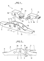
- Figure 1 is an exploded view of a wiper provided with the lateral connection device according to a preferred embodiment of the invention.
- Figure 2 is a longitudinal view of the device according to Figure 1, in the working position, the frame carrying the scanning blade being in section.
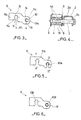
- Figure 3 is a view of the connecting device alone.
- FIG. 4 is a sectional view along line II of FIG. 2.
- Figure 5 is a view of the connecting device according to another embodiment.
- Figure 6 is a view of the connecting device according to another embodiment.
- the lateral connection device of a wiper blade (not shown) is disposed in a known manner at the end 1a of a drive arm 1 which is constituted by a yoke 2 in the shape of a U whose wings lateral 2 0 are crossed perpendicularly and freely by a cylindrical axis 3 extending outside - laughing by a part on which is formed a groove 4 cooperating with the connecting device 9 to form an axis of articulation to the wiper blade -window comprising a rubber scanning blade (not shown) connected by lifting beams to a main frame 5 whose walls 6 are crossed by a fixed axis 7 and whose back part 8 is open to allow the translation of the device liaison 9.
- the connecting device 9 is constituted by a nut comprising on the one hand a transverse opening 10 in the form of an open buttonhole menoqée at one of its ends 9a to constitute a jaw elastic capable of fitting in the manner of a fork in the groove 4 of the articulation axis and on the other hand a second opening 11 in the form of a buttonhole open approximately, perpendicular to the first 10 and formed at the another end 9b of the nut 9 to constitute another elastic jaw capable of engaging, in the manner of a hook, by rotation about the articulation axis 3.
- the articulation axis 3 which is arranged at the end as seen above is previously engaged in two holes 12 and 13 opposite, of corresponding diameter, formed in the walls 6 of the main frame 5 of the brush, at a distance d from the fixed axis 7 equal at the center line dl of the cylindrical bottoms ics 14 and 15 of the open buttonholes 10 and 11.
- the walls 10a and 11a constituting the jaws are slightly flared.
- the buttonhole 10 has on its inner contour a rim 16 of dimensions slightly lower than those of the buttonhole 10 in order to form a shoulder on which the on both sides, the sides 4a of the groove 4 in order to ensure the retention in translation of the hinge pin 3 on the brush from where the arm 1 on said brush via the connecting nut 9.
- the embodiment shown in FIG. 5 differs essentially from the previous one in that the housings corresponding on the one hand to the fixed axis 7 and on the other hand to the articulation axis 3 are constituted by two open buttonholes 11 A and 10 A whose longitudinal axes YY 'and ZZ' are mutually parallel, buttonholes constituting two elastic jaws opt to engage simultaneously on the fixed axis 7 and on the articulation axis 3 by simple pressure on the back of the nut 9.
- the embodiment shown in FIG. 6 differs essentially from the previous ones in that the housings corresponding on the one hand to the fixed axis 7 and on the other hand to the articulation axis 3 are 'constituted respectively by an open buttonhole 11 B and a hole 10 B made elastic by a radial slot 17 so as to allow the transverse engagement of the hinge pin 3 after having compared the hole 10 B of the nut 9 with the holes 12 and 13 of the frame 5, inside the open dorsal part 8 of said frame so that said hinge pin 3 snaps resiliently into the nut 9 by transverse insertion after passing through the walls 6 of the frame 5.
- the buttonhole 11 B can then be engaged in the manner of a hook on the fixed axis 7 of the brush by rotation of the nut 9 on the articulation axis 7.
- the buttonhole 11 can be inclined so that its longitudinal axis is located approximately on the tangent of the circle described by the pivot radius of the nut 9 so as to facilitate its anchoring by pivoting.
Abstract
Description
- La présente invention concerne un dispositif de liaison latérale d'un balai d'essuie-glace à l'extrémité d'un bras d'entrainement qui .est constitué par une chape en forme de U dont les ailes latérales sont traversées perpendiculairement par un axe cylindrique se prolongeant à l'extérieur par une partie sur laquelle est ménagée une gorge coopérant avec le dispositif de liaison pour constituer un axe d'articulation au balai d'essuie-glace comportant une lame de balayage en caoutchouc reliée par des palonniers à une armature principale dont les parois sont traversées par un axe fixe dont la partie dorsale est ouverte pour permettre l'introduction du dispositif de liaison.
- Il est connu un dispositif de liaisonde ce type (demande de brevet nO 79 06550 au nom de la demanderesse) comportant des moyens de verrouillage coopérant avec la gorge de l'axe d'articulation et constitués par une ouverture en forme de boutonnière dont une extrémité est de dimensions telles à autoriser la pénétration de l'axe d'articulation qui vient en butée contre l'extérieur d'une face du bras d'entrainement, et dont l'autre extrémité comprend un rebord formant un épaulement d'appui pour la gorge dudit axe et dont la partie médiane est de dimensions sensiblement inférieures à la dimension du fond de la gorge dudit axe et se déforme élastiquement sous l'effet dudit fond de la gorge lors du mouvement de translation jusqu'à ce que ladite gorge soit bien positionnée contre l'épaulement d'appui, position à partir de laquelle la partie médiane reprend sa forme initiale de manière à assurer le verrouillage élastique du dispositif de liaison sur l'axe d'articulation préalablement monté à l'extrémité du bras. Le dispositif de liaison ainsi monté sur le bras est solidarisé au balai d'essuie-glace grâce à une lumière ouverte en forme de crochet venant entourer élastiquement pour le verrouiller, l'axe fixe d'origine du balai.
- L'inconvénient majeur de ce dispositif se situe essentiellement au'niveau du montage car la lumière en forme de crochet ménagée à l'extrémité de l'organe de liaison et l'ouverture en forme de boutonnière enserrant l'axe d'articulation sont ménagées suivant des plans sensiblement parallèles et par conséquent en tirant sur le bras muni du dispositif de liaison pour verrouiller le balai par l'intermédiaire du crochet on tend à dévérouiller l'axe d'articulation du bras précédemment assemblé sur le dispositif de licison.
- Le but de la présente invention est de remédier à ces inconvénients et concerne à cet effet un dispositif de liaison latérale d'un balai d'essuie-glace à l'extrémité d'un bras d'entraînement qui est constitué par une chape en forme de U dont les ailes latérales sont traversées perpendiculairement par un axe cylindrique se prolongeant à l'extérieur par une partie sur laquelle est ménagée une gorge coopérant avec le dispositif de liaison pour constituer un axe d'articulation ou balai d'essuie-glace comportant une lame de balayage en caoutchouc reliée par des palonniers à une armature principale dont les parois sont traversées par un axe fixe et dont la partie dorsale est ouverte pour permettre l'introduction du dispositif de liaison caractérisé en ce que le dispositif de liaison, avantageusement réalisé en matière plastique, est constitué par une noix insérée dans la partie dorsale ouverte de l'armature principale et comportant deux logements dont l'un est traversé par l'axe fixe du balai et l'autre par l'axe d'articulation qui disposé à l'extrémité du bras est engagé préalablement ou ultérieurement dans deux trous de diamètre correspondant pratiqués en vis à vis dans les parois de l'armature principale du balai à une distance l'un de l'autre égale à celle séparant les deux logements.
- Selon un mode de réalisation particulier les deux logements (10 et 11) sont constitués par deux boutonnières ouvertes perpendiculaires entre elles et constituant deux mâchoires élastiques optent à s'engager successivement et respectivement sur l'axe d'articulation (3), préalablement engagé, à la manière d'une fourche et sur l'axe fixe (7) du balai à la manière d'un crochet par rotation autour de l'axe d'articulation (3).
- La description qui va suivre en regard des dessins annexés fera mieux comprendre comment l'invention peut être réalisée.
- La figure 1 est une vue éclatée d'un essuie-glace muni du dispositif de liaison latérale suivant un mode préférentiel de réalisation de l'invention.
- La figure 2 est une vue longitudinale du dispositif suivant la figure 1, en position travail, l'armature portant la lame de balayage étant en coupe.
- La figure 3 est une vue du dispositif de liaison seul.
- La figure 4 est une vue en coupe suivant la ligne II de la figure 2. La figure 5 est une vue du dispositif de liaison suivant un autre mode de réalisation.
- La figure 6 est une vue du dispositif de liaison suivant un autre mode de réalisation.
- Le dispositif de liaison latérale d'un balai d'essuie-glace (non représenté) est disposé de manière connue à l'extrémité la d'un bras d'entraînement 1 qui est constituée par une chape 2 en forme de U dont les ailes latérales 20 sont traversées perpendiculairement et librement par un axe cylindrique 3 se prolongeant à l'exté - rieur par une partie sur laquelle est ménagée une gorge 4 coopérant avec le dispositif de liaison 9 pour constituer un axe d'articulation au balai d'essuie-glace comportant une lame de balayage en caoutchouc (non représentée) reliée par des palonniers à une armature principale 5 dont les parois 6 sont traversées par un axe fixe 7 et dont la partie dorsale 8 est ouverte pour permettre l'in traduction du dispositif de liaison 9.
- Suivant un mode préféré de réalisation le dispositif de liaison 9, avantaqeusement réalisé en matière plastique, est constitué par une noix comportant d'une part une ouverture transversale 10 en forme de boutonnière ouverte ménoqée à l'une de ses extrémités 9a pour constituer une mâchoire élastique apte à s'enqager à la manière d'une fourche dans la gorge 4 de l'axe d'articulation et d'autre part une seconde ouverture 11 en forme de boutonnière ouverte approximativement, perpendiculaire à la première 10 et ménagée à l'autre extrémité 9b de la noix 9 pour constituer une autre machoire élastique apte à s'engager, à la manière d'un crochet, par rotation autour de l'axe d'articulation 3. L'axe d'articulation 3 qui est disposé à l'extrémité la comme vu précédemment est préalablement engagé dans deux trous 12 et 13 en vis à vis, de diamètre correspondant, pratiqués dans les parois 6 de l'armature principale 5 du balai, à une distance d de l'axe fixe 7 égale à l'entre axe dl des fonds cylindriques 14 et 15 des boutonnières ouvertes 10 et 11.
- Afin de faciliter l'engagement des boutonnières ouvertes 10 et 11 sur leur axe respectif 7 et 3 les parois 10a et 11a constituant les machoires sont légèrement évasées.
- De plus la boutonnière 10 comporte sur son contour intérieur un rebord 16 de dimensions légèremen inFérieures à celles de la boutonnière 10 pour former un épaulement sur lequel s'appuient de part et d'autre, les flancs 4a de la gorge 4 afin d'assurer la retenue en translation de l'axe d'articulation 3 sur le balai d'où du bras 1 sur ledit balai par l'intermédiaire de la noix de liaison 9.
- Le mode de réalisation représenté à la figure 5 diffère essentiellement du précédent en ce que les logements correspondants d'une part à l'axe fixe 7 et d'autre part à l'axe d'articulation 3 sont constitués par deux boutonnières ouvertes 11 A et 10 A dont leur axe longitudinaux YY' et ZZ' sont parallèles entre eux, boutonnières constituant deux mâchoires élastiques optent à s'engager simultanément sur l'axe fixe 7 et sur l'axe d'articulation 3 par simple pression sur le dos de la noix 9.
- Le mode de réalisation représenté à la figure 6 diffère essentiellement des précédents en ce que les logements correspondants d'une part à l'axe fixe 7 et d'outre part à l'axe d'articulation 3 sont' constituées respectivement par une boutonnière ouverte 11 B et un trou 10 B rendu élastique par une fente radiale 17 de manière à permettre l'engagement transversal de l'axe d'articulation 3 après avoir mis en regard le trou 10 B de la noix 9 avec les trous 12 et 13 de l'armature 5, à l'intérieur de la partie dorsale ouverte 8 de ladite armature de manière à ce que ledit axe d'articulation 3 s'encliquette élastiquement dans la noix 9 par introduction transversale après avoir traversé les parois 6 de l'armature 5. La boutonnière 11 B peut alors être engagée à la manière d'un crochet sur l'axe fixe 7 du balai par rotation de la noix 9 sur l'axe d'articulation 7.
- Il est bien entendu que de nombreuses modifications peuvent être apportées à ces modes de réalisation sans pour cela sortir du cadre de la présente invention comme par exemple dans le premier mode de réalisation la boutonnière 11 peut être inclinée de manière à ce que son axe longitudinal soit situé approximativement sur la tangente du cercle décrit par le rayon de pivotement de la noix 9 de manière à faciliter son ancrage par pivotement.
Claims (4)
Applications Claiming Priority (2)
| Application Number | Priority Date | Filing Date | Title |
|---|---|---|---|
| FR8025733A FR2495557B1 (fr) | 1980-12-04 | 1980-12-04 | Dispositif de liaison laterale d'un balai d'essuie-glace |
| FR8025733 | 1980-12-04 |
Publications (2)
| Publication Number | Publication Date |
|---|---|
| EP0053960A1 true EP0053960A1 (fr) | 1982-06-16 |
| EP0053960B1 EP0053960B1 (fr) | 1985-04-24 |
Family
ID=9248649
Family Applications (1)
| Application Number | Title | Priority Date | Filing Date |
|---|---|---|---|
| EP81401808A Expired EP0053960B1 (fr) | 1980-12-04 | 1981-11-18 | Dispositif de liaison latérale d'un balai d'essuie glace |
Country Status (4)
| Country | Link |
|---|---|
| EP (1) | EP0053960B1 (fr) |
| DE (1) | DE3170190D1 (fr) |
| ES (1) | ES270023Y (fr) |
| FR (1) | FR2495557B1 (fr) |
Cited By (16)
| Publication number | Priority date | Publication date | Assignee | Title |
|---|---|---|---|---|
| FR2574732A1 (fr) * | 1984-12-18 | 1986-06-20 | Champion Spark Plug Europ | Dispositif d'attache pour balais d'essuie-glace |
| DE3625063A1 (de) * | 1986-07-24 | 1988-02-04 | Swf Auto Electric Gmbh | Wischblatt, insbesondere zur reinigung von scheiben an kraftfahrzeugen |
| US5084933A (en) * | 1990-10-19 | 1992-02-04 | Franz Buechele | Adaptor for windshield wiper arms |
| US5182831A (en) * | 1991-01-17 | 1993-02-02 | Trico Products Corporation | Windscreen wiper blade arrangement with orientation indicating means |
| US5383248A (en) * | 1991-03-29 | 1995-01-24 | Ho; Chang S. Y. | Structure of double-blade wind shieldwiper with arm to blade connectors |
| US5392487A (en) * | 1993-12-15 | 1995-02-28 | Yang; Ming-Tung | Universal windshield wiper and wiper arm connector |
| US5611103A (en) * | 1993-09-10 | 1997-03-18 | Lee; Albert | Windshield wiper frame connector which accomodates different size wiper arms |
| EP0560851B2 (fr) † | 1990-12-04 | 2001-08-22 | Lego A/S | Mecanisme d'accouplement pour jeu de construction |
| WO2003051696A1 (fr) * | 2001-12-19 | 2003-06-26 | Robert Bosch Gmbh | Essuie-glace monobras |
| WO2003051688A2 (fr) * | 2001-12-19 | 2003-06-26 | Robert Bosch Gmbh | Essuie-glace dote d'un bras |
| WO2003051695A3 (fr) * | 2001-12-19 | 2003-10-16 | Bosch Gmbh Robert | Essuie-glace dote d'un bras |
| FR2838693A1 (fr) * | 2002-04-22 | 2003-10-24 | Valeo Systemes Dessuyage | Agencement de fixation d'une monture de balai d'essuie glace sur un bras |
| WO2004041604A1 (fr) * | 2002-11-04 | 2004-05-21 | Valeo Systèmes d'Essuyage | Adaptateur pour balai d'essuie-glace |
| CN105459962A (zh) * | 2014-06-06 | 2016-04-06 | 扬弘实业股份有限公司 | 刮水板及其转接器 |
| EP3159224A1 (fr) * | 2015-10-22 | 2017-04-26 | Valeo Systèmes d'Essuyage | Dispositif de connexion interposé entre un bras de manoeuvre et un balai d'essuyage d'une surface vitrée de véhicule |
| US20170136995A1 (en) * | 2015-11-17 | 2017-05-18 | Valeo Systèmes d'Essuyage | Cover equipping a connector for a motor vehicle wiper |
Citations (7)
| Publication number | Priority date | Publication date | Assignee | Title |
|---|---|---|---|---|
| FR2361253A1 (fr) * | 1976-08-12 | 1978-03-10 | J B Brevets | Perfectionnements aux balais d'essuie-glace a profil bas |
| CH609287A5 (en) * | 1976-12-20 | 1979-02-28 | Tech Handelsberatung Establish | Windscreen wiper for motor vehicles |
| CH611563A5 (en) * | 1977-04-04 | 1979-06-15 | Tech Handelsberatung Establish | Motor vehicle windscreen wiper with means for retaining the pin of the wiper arm |
| EP0012847A1 (fr) * | 1978-12-23 | 1980-07-09 | Robert Bosch Gmbh | Essuie-glace pour véhicule automobile |
| FR2451297A1 (fr) * | 1979-03-15 | 1980-10-10 | Ducellier & Cie | Dispositif de retenue et d'articulation d'un balai d'essuie-glace |
| GB2067068A (en) * | 1980-01-11 | 1981-07-22 | Bosso Fister Sas | Connection system for the connection of windshield wiper blades to wiper arms |
| FR2475481A1 (fr) * | 1980-02-13 | 1981-08-14 | Archambel Sa | Connecteur pour balai d'essui-glace |
Family Cites Families (3)
| Publication number | Priority date | Publication date | Assignee | Title |
|---|---|---|---|---|
| US4118825A (en) * | 1977-03-28 | 1978-10-10 | Monroe Auto Equipment Company | Connector assembly for windshield wipers |
| DE2753117A1 (de) * | 1977-11-29 | 1979-06-07 | Bosch Gmbh Robert | Wischvorrichtung fuer scheiben von kraftfahrzeugen |
| DE2756317A1 (de) * | 1977-12-17 | 1979-06-21 | Bosch Gmbh Robert | Wischvorrichtung fuer scheiben von kraftfahrzeugen |
-
1980
- 1980-12-04 FR FR8025733A patent/FR2495557B1/fr not_active Expired
-
1981
- 1981-11-18 DE DE8181401808T patent/DE3170190D1/de not_active Expired
- 1981-11-18 EP EP81401808A patent/EP0053960B1/fr not_active Expired
- 1981-12-03 ES ES1981270023U patent/ES270023Y/es not_active Expired
Patent Citations (9)
| Publication number | Priority date | Publication date | Assignee | Title |
|---|---|---|---|---|
| FR2361253A1 (fr) * | 1976-08-12 | 1978-03-10 | J B Brevets | Perfectionnements aux balais d'essuie-glace a profil bas |
| CH609287A5 (en) * | 1976-12-20 | 1979-02-28 | Tech Handelsberatung Establish | Windscreen wiper for motor vehicles |
| CH611563A5 (en) * | 1977-04-04 | 1979-06-15 | Tech Handelsberatung Establish | Motor vehicle windscreen wiper with means for retaining the pin of the wiper arm |
| EP0012847A1 (fr) * | 1978-12-23 | 1980-07-09 | Robert Bosch Gmbh | Essuie-glace pour véhicule automobile |
| FR2451297A1 (fr) * | 1979-03-15 | 1980-10-10 | Ducellier & Cie | Dispositif de retenue et d'articulation d'un balai d'essuie-glace |
| GB2067068A (en) * | 1980-01-11 | 1981-07-22 | Bosso Fister Sas | Connection system for the connection of windshield wiper blades to wiper arms |
| DE3047953A1 (de) * | 1980-01-11 | 1981-10-08 | Fister S.a.s. di Bosso Giacomo & C., Torino | Einrichtung zum verbinden eines wischerblattes fuer eine windschutzscheibe mit einem betaetigungsarm |
| FR2475481A1 (fr) * | 1980-02-13 | 1981-08-14 | Archambel Sa | Connecteur pour balai d'essui-glace |
| GB2072497A (en) * | 1980-02-13 | 1981-10-07 | Champion Spark Plug Europ | Connecting device for attaching a wiper blade to wiper arms of different types |
Cited By (29)
| Publication number | Priority date | Publication date | Assignee | Title |
|---|---|---|---|---|
| FR2574732A1 (fr) * | 1984-12-18 | 1986-06-20 | Champion Spark Plug Europ | Dispositif d'attache pour balais d'essuie-glace |
| US4649591A (en) * | 1984-12-18 | 1987-03-17 | Champion Spark Plug Europe S.A. | Connector for wiper blades |
| AU573409B2 (en) * | 1984-12-18 | 1988-06-09 | Champion Spark Plug Europe S.A. | Wiper blade assembly |
| DE3625063A1 (de) * | 1986-07-24 | 1988-02-04 | Swf Auto Electric Gmbh | Wischblatt, insbesondere zur reinigung von scheiben an kraftfahrzeugen |
| US5084933A (en) * | 1990-10-19 | 1992-02-04 | Franz Buechele | Adaptor for windshield wiper arms |
| EP0560851B2 (fr) † | 1990-12-04 | 2001-08-22 | Lego A/S | Mecanisme d'accouplement pour jeu de construction |
| US5182831A (en) * | 1991-01-17 | 1993-02-02 | Trico Products Corporation | Windscreen wiper blade arrangement with orientation indicating means |
| AU648861B2 (en) * | 1991-01-17 | 1994-05-05 | Trico-Folberth Limited | Windscreen wiper blade arrangement |
| US5383248A (en) * | 1991-03-29 | 1995-01-24 | Ho; Chang S. Y. | Structure of double-blade wind shieldwiper with arm to blade connectors |
| US5435041A (en) * | 1991-03-29 | 1995-07-25 | Ho; Chang S. Y. | Double bladed windshield wiper and drive arm conector therefor |
| US5611103A (en) * | 1993-09-10 | 1997-03-18 | Lee; Albert | Windshield wiper frame connector which accomodates different size wiper arms |
| US5392487A (en) * | 1993-12-15 | 1995-02-28 | Yang; Ming-Tung | Universal windshield wiper and wiper arm connector |
| WO2003051695A3 (fr) * | 2001-12-19 | 2003-10-16 | Bosch Gmbh Robert | Essuie-glace dote d'un bras |
| WO2003051688A2 (fr) * | 2001-12-19 | 2003-06-26 | Robert Bosch Gmbh | Essuie-glace dote d'un bras |
| WO2003051696A1 (fr) * | 2001-12-19 | 2003-06-26 | Robert Bosch Gmbh | Essuie-glace monobras |
| WO2003051688A3 (fr) * | 2001-12-19 | 2003-10-16 | Bosch Gmbh Robert | Essuie-glace dote d'un bras |
| US6789289B2 (en) | 2001-12-19 | 2004-09-14 | Robert Bosch Gmbh | Windscreen wiper comprising a wiper arm |
| US6792644B2 (en) | 2001-12-19 | 2004-09-21 | Robert Bosch Gmbh | Windscreen wiper with a wiper arm |
| FR2838693A1 (fr) * | 2002-04-22 | 2003-10-24 | Valeo Systemes Dessuyage | Agencement de fixation d'une monture de balai d'essuie glace sur un bras |
| WO2004041604A1 (fr) * | 2002-11-04 | 2004-05-21 | Valeo Systèmes d'Essuyage | Adaptateur pour balai d'essuie-glace |
| CN100377936C (zh) * | 2002-11-04 | 2008-04-02 | 瓦莱奥清洗系统公司 | 用于刮水片的转接器 |
| CN105459962A (zh) * | 2014-06-06 | 2016-04-06 | 扬弘实业股份有限公司 | 刮水板及其转接器 |
| CN105459962B (zh) * | 2014-06-06 | 2020-07-31 | 罗伯特·博世有限公司 | 刮水板 |
| EP3159224A1 (fr) * | 2015-10-22 | 2017-04-26 | Valeo Systèmes d'Essuyage | Dispositif de connexion interposé entre un bras de manoeuvre et un balai d'essuyage d'une surface vitrée de véhicule |
| FR3042760A1 (fr) * | 2015-10-22 | 2017-04-28 | Valeo Systemes Dessuyage | Dispositif de connexion interpose entre un bras de manœuvre et un balai d’essuyage d’une surface vitree de vehicule. |
| CN107010014A (zh) * | 2015-10-22 | 2017-08-04 | 法雷奥系统公司 | 用于车辆玻璃表面的插入操作臂和刮水器之间的连接装置 |
| CN107010014B (zh) * | 2015-10-22 | 2019-07-09 | 法雷奥系统公司 | 用于车辆玻璃表面的插入操作臂和刮水器之间的连接装置 |
| US20170136995A1 (en) * | 2015-11-17 | 2017-05-18 | Valeo Systèmes d'Essuyage | Cover equipping a connector for a motor vehicle wiper |
| US10618500B2 (en) * | 2015-11-17 | 2020-04-14 | Vale Systèmes d'Essuyage | Cover equipping a connector for a motor vehicle wiper |
Also Published As
| Publication number | Publication date |
|---|---|
| FR2495557A1 (fr) | 1982-06-11 |
| EP0053960B1 (fr) | 1985-04-24 |
| ES270023U (es) | 1983-10-01 |
| DE3170190D1 (en) | 1985-05-30 |
| FR2495557B1 (fr) | 1985-06-07 |
| ES270023Y (es) | 1984-03-16 |
Similar Documents
| Publication | Publication Date | Title |
|---|---|---|
| EP0053960B1 (fr) | Dispositif de liaison latérale d'un balai d'essuie glace | |
| EP0632991B1 (fr) | Balai-éponge | |
| EP0410854B1 (fr) | Déflecteur d'air mobile pour balai d'essuie-glace, notamment de véhicule automobile | |
| FR2596711A3 (fr) | Bras de monture d'essuie-glace de pare-brise | |
| FR2482541A1 (fr) | Dispositif de liaison servant a raccorder le bras et le balai d'un essuie-glace | |
| EP0479659B1 (fr) | Bras d'essuie-glace notamment pour véhicule automobile | |
| FR2625152A1 (fr) | Dispositif d'essuie-glace | |
| EP0788950A1 (fr) | Dispositif d'essuie-glace, notamment pour un véhicule automobile, muni de moyens d'indexation de l'essuie-glace par rapport à un arbre d'entraînement | |
| EP0433169B1 (fr) | Dispositif déflecteur pour balai d'essuie-glace | |
| FR2647401A1 (fr) | Dispositif d'essuie-glace pour un vehicule automobile comportant des moyens perfectionnes de liaison d'une armature de balai sur un bras | |
| EP1021122B1 (fr) | Ensemble constitué d'un dispositif d'essorage et d'un balai comportant une tête de balai et un manche | |
| FR2647402A1 (fr) | Dispositif d'essuie-glace pour un vehicule automobile comportant des moyens perfectionnes de liaison d'une armature balai sur un bras | |
| EP2883760A1 (fr) | Agrafe de fixation d'un tuyau de circulation de fluide à un bras d'entraînement d'un balai d'essuie-glace de véhicule | |
| FR2692215A1 (fr) | Dispositif d'essuie-glace à liaison esthétique entre le carter et la tête d'entraînement. | |
| EP0565436B1 (fr) | Bras d'essuie-glace | |
| FR2673152A1 (fr) | Articulation d'un etrier de balai d'essuie-glace a un bras d'essuie-glace d'un systeme essuie-glace. | |
| FR2851267A1 (fr) | Dispositif permettant d'associer des barrieres | |
| FR2594767A1 (fr) | Attache pour la fixation d'un balai d'essuie-glace a axe d'articulation sur un bras en forme de crochet | |
| FR2492750A1 (fr) | Dispositif de liaison articulee pour balai d'essuie-glace | |
| FR2756239A1 (fr) | Dispositif d'essuyage d'une vitre de vehicule automobile comportant des moyens perfectionnes d'accrochage d'un balai d'essuie-glace | |
| FR2569642A1 (fr) | Embout d'articulation destine a etre monte a l'extremite d'un bras d'essuie-glace, et bras d'essuie-glace equipe d'un tel embout | |
| WO2021170359A1 (fr) | Capot pour un dispositif de connexion d'un systeme d'essuyage | |
| FR3030410A1 (fr) | Capot pour un bras d'essuie-glace | |
| FR2562852A1 (fr) | Systeme d'essuie-glace pour vehicules a moteur | |
| FR2671528A1 (fr) | Etrier modulaire pour balai d'essuie-glace. |
Legal Events
| Date | Code | Title | Description |
|---|---|---|---|
| PUAI | Public reference made under article 153(3) epc to a published international application that has entered the european phase |
Free format text: ORIGINAL CODE: 0009012 |
|
| AK | Designated contracting states |
Designated state(s): DE GB IT |
|
| 17P | Request for examination filed |
Effective date: 19820924 |
|
| ITF | It: translation for a ep patent filed |
Owner name: SOCIETA' ITALIANA BREVETTI S.P.A. |
|
| GRAA | (expected) grant |
Free format text: ORIGINAL CODE: 0009210 |
|
| AK | Designated contracting states |
Designated state(s): DE GB IT |
|
| REF | Corresponds to: |
Ref document number: 3170190 Country of ref document: DE Date of ref document: 19850530 |
|
| PLBE | No opposition filed within time limit |
Free format text: ORIGINAL CODE: 0009261 |
|
| STAA | Information on the status of an ep patent application or granted ep patent |
Free format text: STATUS: NO OPPOSITION FILED WITHIN TIME LIMIT |
|
| 26N | No opposition filed | ||
| PG25 | Lapsed in a contracting state [announced via postgrant information from national office to epo] |
Ref country code: GB Effective date: 19881118 |
|
| GBPC | Gb: european patent ceased through non-payment of renewal fee | ||
| PG25 | Lapsed in a contracting state [announced via postgrant information from national office to epo] |
Ref country code: DE Effective date: 19890801 |