EP0053906A2 - Umschlagvorrichtung für Reifenaufbaumaschinen - Google Patents
Umschlagvorrichtung für Reifenaufbaumaschinen Download PDFInfo
- Publication number
- EP0053906A2 EP0053906A2 EP81305664A EP81305664A EP0053906A2 EP 0053906 A2 EP0053906 A2 EP 0053906A2 EP 81305664 A EP81305664 A EP 81305664A EP 81305664 A EP81305664 A EP 81305664A EP 0053906 A2 EP0053906 A2 EP 0053906A2
- Authority
- EP
- European Patent Office
- Prior art keywords
- rings
- assembly
- fingers
- set forth
- ring
- Prior art date
- Legal status (The legal status is an assumption and is not a legal conclusion. Google has not performed a legal analysis and makes no representation as to the accuracy of the status listed.)
- Withdrawn
Links
Images
Classifications
-
- B—PERFORMING OPERATIONS; TRANSPORTING
- B29—WORKING OF PLASTICS; WORKING OF SUBSTANCES IN A PLASTIC STATE IN GENERAL
- B29D—PRODUCING PARTICULAR ARTICLES FROM PLASTICS OR FROM SUBSTANCES IN A PLASTIC STATE
- B29D30/00—Producing pneumatic or solid tyres or parts thereof
- B29D30/06—Pneumatic tyres or parts thereof (e.g. produced by casting, moulding, compression moulding, injection moulding, centrifugal casting)
- B29D30/08—Building tyres
- B29D30/20—Building tyres by the flat-tyre method, i.e. building on cylindrical drums
- B29D30/32—Fitting the bead-rings or bead-cores; Folding the textile layers around the rings or cores
-
- B—PERFORMING OPERATIONS; TRANSPORTING
- B29—WORKING OF PLASTICS; WORKING OF SUBSTANCES IN A PLASTIC STATE IN GENERAL
- B29D—PRODUCING PARTICULAR ARTICLES FROM PLASTICS OR FROM SUBSTANCES IN A PLASTIC STATE
- B29D30/00—Producing pneumatic or solid tyres or parts thereof
- B29D30/06—Pneumatic tyres or parts thereof (e.g. produced by casting, moulding, compression moulding, injection moulding, centrifugal casting)
- B29D30/08—Building tyres
- B29D30/10—Building tyres on round cores, i.e. the shape of the core is approximately identical with the shape of the completed tyre
- B29D30/16—Applying the layers; Guiding or stretching the layers during application
-
- B—PERFORMING OPERATIONS; TRANSPORTING
- B29—WORKING OF PLASTICS; WORKING OF SUBSTANCES IN A PLASTIC STATE IN GENERAL
- B29D—PRODUCING PARTICULAR ARTICLES FROM PLASTICS OR FROM SUBSTANCES IN A PLASTIC STATE
- B29D30/00—Producing pneumatic or solid tyres or parts thereof
- B29D30/06—Pneumatic tyres or parts thereof (e.g. produced by casting, moulding, compression moulding, injection moulding, centrifugal casting)
- B29D30/08—Building tyres
- B29D30/20—Building tyres by the flat-tyre method, i.e. building on cylindrical drums
- B29D30/32—Fitting the bead-rings or bead-cores; Folding the textile layers around the rings or cores
- B29D2030/3221—Folding over means, e.g. bladders or rigid arms
- B29D2030/3278—Folding down the ends of the tubular tyre component, e.g. the carcass, over the drum shoulders
-
- Y—GENERAL TAGGING OF NEW TECHNOLOGICAL DEVELOPMENTS; GENERAL TAGGING OF CROSS-SECTIONAL TECHNOLOGIES SPANNING OVER SEVERAL SECTIONS OF THE IPC; TECHNICAL SUBJECTS COVERED BY FORMER USPC CROSS-REFERENCE ART COLLECTIONS [XRACs] AND DIGESTS
- Y10—TECHNICAL SUBJECTS COVERED BY FORMER USPC
- Y10T—TECHNICAL SUBJECTS COVERED BY FORMER US CLASSIFICATION
- Y10T29/00—Metal working
- Y10T29/49—Method of mechanical manufacture
- Y10T29/49826—Assembling or joining
- Y10T29/4984—Retaining clearance for motion between assembled parts
- Y10T29/49844—Through resilient media
-
- Y—GENERAL TAGGING OF NEW TECHNOLOGICAL DEVELOPMENTS; GENERAL TAGGING OF CROSS-SECTIONAL TECHNOLOGIES SPANNING OVER SEVERAL SECTIONS OF THE IPC; TECHNICAL SUBJECTS COVERED BY FORMER USPC CROSS-REFERENCE ART COLLECTIONS [XRACs] AND DIGESTS
- Y10—TECHNICAL SUBJECTS COVERED BY FORMER USPC
- Y10T—TECHNICAL SUBJECTS COVERED BY FORMER US CLASSIFICATION
- Y10T29/00—Metal working
- Y10T29/49—Method of mechanical manufacture
- Y10T29/49826—Assembling or joining
- Y10T29/4984—Retaining clearance for motion between assembled parts
- Y10T29/49845—Retaining clearance for motion between assembled parts by deforming interlock
-
- Y—GENERAL TAGGING OF NEW TECHNOLOGICAL DEVELOPMENTS; GENERAL TAGGING OF CROSS-SECTIONAL TECHNOLOGIES SPANNING OVER SEVERAL SECTIONS OF THE IPC; TECHNICAL SUBJECTS COVERED BY FORMER USPC CROSS-REFERENCE ART COLLECTIONS [XRACs] AND DIGESTS
- Y10—TECHNICAL SUBJECTS COVERED BY FORMER USPC
- Y10T—TECHNICAL SUBJECTS COVERED BY FORMER US CLASSIFICATION
- Y10T29/00—Metal working
- Y10T29/49—Method of mechanical manufacture
- Y10T29/49826—Assembling or joining
- Y10T29/49863—Assembling or joining with prestressing of part
- Y10T29/4987—Elastic joining of parts
Definitions
- This invention relates generally as indicated to a ply down assembly for a tire building machine and more particularly to a ply down and bead set assembly in which an array of axially projecting spring fingers are employed.
- Spring finger ply downs are generally employed at each axial end of the drum of-a tire building machine.
- Such assemblies generally comprise an array of axially extending spring fingers which project-toward the center of the drum and which in their unflexed condition extend at an angle radially outwardly.
- Such fingers are usually flexed inwardly by the axial movement of a bead setting device causing the ends thereof to sweep or fold inwardly liner or ply material overhanging the ends of the drum. In this manner the materials of the tire are turned down over the shoulder or edge of the drum to form a shoulder of tire material rigidly backed by the edge or shoulder of the drum to receive the tire bead.
- the ply material will normally be turned and stitched around the bead and up over the top of the drum by a dual bladder assembly such as seen, for example, in Cantarutti U.S. Patent No. 3,438,832, or the copending application of George E. Enders entitled “Tire Building Machine” Serial No. 122,605, filed February 19, 1980.
- the problem is similar to trying to assemble a barrel without special tools or jigs, or trying to replace a single barrel stave without affecting adjacent barrel staves.
- the fingers are clamped between two rings but to assemble the fingers or remove a single finger requires the rings to be separated sufficiently to accomplish the purpose. This is difficult to do without affecting or loosening adjacent fingers.
- Another important object is the provision of such assembly wherein the fingers can individually quickly be removed or reinserted without affecting adjacent fingers.
- a similar object is the provision of such assembly wherein the fingers may be inserted, or removed, without requiring the disassembly of parts.
- Another object is the provision of a spring finger assembly for a tire building machine wherein the fingers may be assembled, removed, or replaced, without the requirement of special tools.
- Still another object is the provision of a tire building machine incorporating a spring finger ply down wherein down time for maintenance or repair is greatly reduced.
- a simple two ring ring assembly is provided to secure the fingers, one ring fitting within the other.
- One ring has projections interfitting with the fingers and one or the other may be locally deformable to enable the fingers to be bent for insertion or removal without affecting adjacent fingers.
- a yet further object is the provision of such nested ring mounting assembly wherein one of such rings is locally deformable.
- a further object is the provision of a nested ring mounting assembly for such fingers, one of which rings has. projections interfitting with the fingers.
- FIG. 10 there is illustrated a tire building machine shown generally at 10.
- the machine illustrated is a first stage machine which simply constructs the tire band which may later be shaped to a toroid or tire shape on a second stage machine where other components such as a belt or tread are assembled. It will, however, be appreciated that the present invention may be utilized with other types of tire building machines such as a single stage machine wherein the band is both formed and shaped.
- the machine includes a conventional tire building drum 12 which may be radially expanded and contracted.
- the drum is provided with two axially oppositely extending shoulders seen at 13 and 14.
- the drum is rotatable on shafting shown schematically at 15.
- the dual bladder assembly includes an inner bladder 19 and an outer bladder 20. In the uninflated condition of such bladders they lie generally flat and beneath the extending shoulder 14.
- bead setter 22 which includes a .shoulder or shelf 23 adapted to receive the bead 24.
- the bead setter ring or assembly 22 is also movable axially of the machine.
- the spring finger ply down assembly 26 includes an axially projecting array of spring fingers 27 which project axially toward the drum 12 inside of the bead setting ring 22.
- the fingers are mounted at their proximal end on a ring mounting assembly shown generally at 28 which comprises nesced rings 29 and 30.
- the mounting assembly and thus the spring finger ply down is mounted for movement axially of the drum as is the bead setting ring and the dual bladder assembly. .It will be appreciated that a dual bladder assembly, bead setting assembly and spring finger ply down will also be provided on the opposite end of the drum although not illustrated in Figures 1 and 2.
- the spring fingers in their normal or unflexed condition extend axially and then radially outwardly as indicated at 32 in Figure 2 so that the distal ends 33 are positioned radially outwardly of the overhanging plys 34. In such unstressed state of the fingers they form a generally axially projecting cone, with the overhanging plys within the cone.
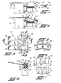
- the rings 29 and 30 are nested with the ring 29 being metallic and including a radially extending leg 39 as well as an axially extending outer somewhat shorter leg 40.
- the leg or flange 40 extends toward the end of the drum in ring form.
- the ring 29 may be connected to a support movable axially of the tire building machine.
- ring 30 Nested within the flange 40 of the ring 29 is ring 30, such rings being interconnected by fasteners 42 extending through holes in L he ring 30 provided with the recessed counterbores 43 accomodating the heads in the recessed fashion illustrated while still providing a large bearing area for the fastener head.
- the ring 30 extends axially substantially beyond the flange 40 and is provided on its outer surface with a series of axially extending flats seen more clearly at 46, 47 and 48 in Figures 6 and 7. Such flats extend between axially extending ribs seen at 50 and 51.
- Each rib is provided with a circular projection as seen at 52 and 53, the centers of which are aligned with the respective ribs.
- Such projections extend slightly beyond ._ the ribs and are offset toward what may be termed the front or projecting edge 54 of the ring 30. In such offset position, the projections 52 are also forward of the front edge 55 of the flange 40 of the ring 29, leaving a slight gap as seen at 56.
- the array of spring fingers 27 includes individual fingers such as seen at 60, 61 and 62, each of which includes lateral circular edge notches which are transversely aligned as seen at 64 and 65. Such notches are designed to mate with the sides of the projections 52, 53, etc. In their attached position, the proximal end 67 of each finger extends beneath the flange 40.
- the fingers In the assembled position of the fingers between the. nested rings, the fingers will be firmly held against axial displacement because of the interfitting projections and notches. Such fingers will also be held because of the snug fit between the flange 40 and the opposed flat on the exterior of the ring 30.
- the ring may be made of a locally deformable material such as a polyurethane elastomer having a durometer hardness of from about 85 to about 95.
- the projections and ribs on the exterior of the ring 30 lock the fingers in place and maintain their proper spacing and alignment when assembled.
- a spring finger ply down assembly is provided which may be assembled in the manner indicated by first assembling the rings 29 and 30, or in which the individual fingers may be removed and replaced without affecting adjoining fingers. Such assembly considerably reduces both assembly time and machine down time for maintenance or repair.
Landscapes
- Engineering & Computer Science (AREA)
- Mechanical Engineering (AREA)
- Tyre Moulding (AREA)
- Tires In General (AREA)
Applications Claiming Priority (2)
| Application Number | Priority Date | Filing Date | Title |
|---|---|---|---|
| US214123 | 1980-12-08 | ||
| US06/214,123 US4353771A (en) | 1980-12-08 | 1980-12-08 | Ply down assembly for tire building machine |
Publications (2)
| Publication Number | Publication Date |
|---|---|
| EP0053906A2 true EP0053906A2 (de) | 1982-06-16 |
| EP0053906A3 EP0053906A3 (de) | 1984-08-01 |
Family
ID=22797867
Family Applications (1)
| Application Number | Title | Priority Date | Filing Date |
|---|---|---|---|
| EP81305664A Withdrawn EP0053906A3 (de) | 1980-12-08 | 1981-12-01 | Umschlagvorrichtung für Reifenaufbaumaschinen |
Country Status (7)
| Country | Link |
|---|---|
| US (1) | US4353771A (de) |
| EP (1) | EP0053906A3 (de) |
| JP (1) | JPS5841190B2 (de) |
| KR (1) | KR850001397B1 (de) |
| AU (1) | AU7760581A (de) |
| BR (1) | BR8107929A (de) |
| CA (1) | CA1164778A (de) |
Cited By (1)
| Publication number | Priority date | Publication date | Assignee | Title |
|---|---|---|---|---|
| EP0199488A3 (de) * | 1985-04-18 | 1988-11-02 | Nrm Corporation | Umfaltfinger für Reifenaufbaumaschine |
Families Citing this family (5)
| Publication number | Priority date | Publication date | Assignee | Title |
|---|---|---|---|---|
| US4584038A (en) * | 1984-01-13 | 1986-04-22 | Nrm Corporation | Tire building method |
| US4705589A (en) * | 1984-01-13 | 1987-11-10 | Nrm Corporation | Tire building machine |
| JP2001260247A (ja) * | 2000-03-17 | 2001-09-25 | Sumitomo Rubber Ind Ltd | 空気入りタイヤの製造方法 |
| US9701083B2 (en) * | 2008-07-23 | 2017-07-11 | Pirelli Tyre S.P.A. | Process and apparatus for manufacturing tyres for vehicle wheels |
| WO2010064066A1 (en) * | 2008-07-23 | 2010-06-10 | Pirelli Tyre S.P.A. | Apparatus and process for manufacturing tyres for vehicle wheels |
Family Cites Families (5)
| Publication number | Priority date | Publication date | Assignee | Title |
|---|---|---|---|---|
| US2998049A (en) * | 1958-01-28 | 1961-08-29 | Goodyear Tire & Rubber | Apparatus for building air spring |
| US3438832A (en) * | 1964-08-17 | 1969-04-15 | Nrm Corp | Tire building machine |
| US3676261A (en) * | 1970-07-06 | 1972-07-11 | Goodyear Tire & Rubber | Bead setting and ply turnup apparatus |
| JPS5221086A (en) * | 1975-08-11 | 1977-02-17 | Mitsubishi Heavy Ind Ltd | Finger ply downing device in tire molder |
| US4238268A (en) * | 1979-02-07 | 1980-12-09 | Mccreary Tire And Rubber Company | Tire building machine ply turn-down finger assembly |
-
1980
- 1980-12-08 US US06/214,123 patent/US4353771A/en not_active Expired - Lifetime
-
1981
- 1981-10-09 JP JP56160349A patent/JPS5841190B2/ja not_active Expired
- 1981-11-18 AU AU77605/81A patent/AU7760581A/en not_active Abandoned
- 1981-11-19 CA CA000390470A patent/CA1164778A/en not_active Expired
- 1981-12-01 EP EP81305664A patent/EP0053906A3/de not_active Withdrawn
- 1981-12-07 BR BR8107929A patent/BR8107929A/pt unknown
- 1981-12-08 KR KR1019810004791A patent/KR850001397B1/ko not_active Expired
Cited By (1)
| Publication number | Priority date | Publication date | Assignee | Title |
|---|---|---|---|---|
| EP0199488A3 (de) * | 1985-04-18 | 1988-11-02 | Nrm Corporation | Umfaltfinger für Reifenaufbaumaschine |
Also Published As
| Publication number | Publication date |
|---|---|
| US4353771A (en) | 1982-10-12 |
| JPS5841190B2 (ja) | 1983-09-10 |
| KR830007280A (ko) | 1983-10-19 |
| JPS5796842A (en) | 1982-06-16 |
| BR8107929A (pt) | 1982-09-14 |
| EP0053906A3 (de) | 1984-08-01 |
| AU7760581A (en) | 1982-06-17 |
| KR850001397B1 (ko) | 1985-09-30 |
| CA1164778A (en) | 1984-04-03 |
Similar Documents
| Publication | Publication Date | Title |
|---|---|---|
| US2145806A (en) | Tire building drum | |
| US4214939A (en) | Tire building machine | |
| EP0431854B1 (de) | Trommel zum Aufbauen von Reifenbestandteilen | |
| CA2058397A1 (en) | Method of forming ply member | |
| EP2698244B1 (de) | Manschettenlose Reifenbautrommel mit auswechselbaren Breitenelementen | |
| US4353771A (en) | Ply down assembly for tire building machine | |
| CA2006988C (en) | Expandable tire building drum | |
| US4427473A (en) | Belt folding machine and method | |
| US4582557A (en) | Tire building machine and method | |
| US3925141A (en) | Machine for manufacturing pneumatic tires, in particular radial tires | |
| US2353767A (en) | Tire building drum | |
| US4402783A (en) | Axially collapsible and expandable tire building drum | |
| US3476633A (en) | Tire building drum | |
| JP2006168367A (ja) | タイヤ製造ドラム用の交錯させられたビード固定セグメント | |
| EP0015113A1 (de) | Reifen Aufbaumaschine und Verfahren | |
| DE2444431A1 (de) | Luftreifenkarkassen-aufbaumaschine mit einer wulsthalteanordnung und verfahren zur verwendung derselben | |
| JP2021503388A (ja) | タイヤ組み立てドラム及びタイヤ組み立て方法 | |
| US4718968A (en) | Finger ply down for tire building machine | |
| US2882139A (en) | Process of manufacture of buffing elements | |
| CA1074540A (en) | Method for mounting a tire bladder | |
| US2214825A (en) | Tire building drum | |
| US4238268A (en) | Tire building machine ply turn-down finger assembly | |
| EP0951986A1 (de) | Einstufige maschine zum formen von radialreifen | |
| US12083761B2 (en) | Shoulder assembly for tire building machine | |
| KR200177796Y1 (ko) | 타이어 성형기용 비드록킹 세그먼트 |
Legal Events
| Date | Code | Title | Description |
|---|---|---|---|
| PUAI | Public reference made under article 153(3) epc to a published international application that has entered the european phase |
Free format text: ORIGINAL CODE: 0009012 |
|
| AK | Designated contracting states |
Designated state(s): DE FR GB IT NL |
|
| 17P | Request for examination filed |
Effective date: 19820915 |
|
| PUAL | Search report despatched |
Free format text: ORIGINAL CODE: 0009013 |
|
| AK | Designated contracting states |
Designated state(s): DE FR GB IT NL |
|
| STAA | Information on the status of an ep patent application or granted ep patent |
Free format text: STATUS: THE APPLICATION IS DEEMED TO BE WITHDRAWN |
|
| 18D | Application deemed to be withdrawn |
Effective date: 19850202 |
|
| RIN1 | Information on inventor provided before grant (corrected) |
Inventor name: YUHAS, GERALD J. |