EP0053829A2 - Garniture pour tours de refroidissement - Google Patents
Garniture pour tours de refroidissement Download PDFInfo
- Publication number
- EP0053829A2 EP0053829A2 EP81110227A EP81110227A EP0053829A2 EP 0053829 A2 EP0053829 A2 EP 0053829A2 EP 81110227 A EP81110227 A EP 81110227A EP 81110227 A EP81110227 A EP 81110227A EP 0053829 A2 EP0053829 A2 EP 0053829A2
- Authority
- EP
- European Patent Office
- Prior art keywords
- elements
- film pack
- sheet
- corrugations
- pack
- Prior art date
- Legal status (The legal status is an assumption and is not a legal conclusion. Google has not performed a legal analysis and makes no representation as to the accuracy of the status listed.)
- Granted
Links
Images


Classifications
-
- F—MECHANICAL ENGINEERING; LIGHTING; HEATING; WEAPONS; BLASTING
- F28—HEAT EXCHANGE IN GENERAL
- F28F—DETAILS OF HEAT-EXCHANGE AND HEAT-TRANSFER APPARATUS, OF GENERAL APPLICATION
- F28F25/00—Component parts of trickle coolers
- F28F25/02—Component parts of trickle coolers for distributing, circulating, and accumulating liquid
- F28F25/08—Splashing boards or grids, e.g. for converting liquid sprays into liquid films; Elements or beds for increasing the area of the contact surface
- F28F25/087—Vertical or inclined sheets; Supports or spacers
Definitions
- THIS INVENTION relates to a pack for cooling towers.
- the invention relates to a film pack for use in cooling towers. More particularly the invention relates to such a film pack for use in wet cooling towers in which a heated liquid is cooled evaporatively by natural or induced air flow.
- 'Film packs known to the applicant comprise a pack or stack of spaced apart sheet elements which can be located substantially vertically within a wet cooling tower and upon which a liquid film of heated liquid can form which can flow under gravity down these elements along the opposing surfaces thereof. This liquid film can thus be cooled by air flowing in an opposite direction to the liquid through the spaces defined between adjacent spaced apart sheet elements.
- the sheet elements may be planar or corrugated, the latter sheets providing an extended contact area for cooling purposes without using additional space.
- a film pack which includes a plurality of substantially parallel at least partially spaced apart asbestos cement sheet elements; and at least one sheet-like intermediate element of a plastics material disposed in a space defined between two adjacent sheet elements.
- the film pack may include sheet-like intermediate elements disposed in spaces defined between all adjacent sheet elements.
- the intermediate elements may be spacer elements for spacing apart adjacent sheet elements.
- the intermediate elements may be substantially rigid.
- the intermediate elements may be in the form of corrugated sheets.
- the intermediate elements may define primary corrugations, the amplitude of the primary corrugations determining the spacing between adjacent sheet elements. More particularly the primary corrugations may be vertically disposed in the operative configuration of the film pack. Also, in a modified embodiment, the primary corrugations may define corrugated paths with respect to the median plane of the intermediate elements.
- intermediate elements may define auxiliary corrugations of smaller amplitude than the primary corrugations and disposed angularly with respect to the primary corrugations.
- the primary and auxiliary corrugations may be mutually orthogonal to one another.
- Intermediate elements having primary and auxiliary corrugations as above defined are substantially rigid, particularly in a direction perpendicular to the plane of the plastics sheet,'so that the spacing between adjacent sheet elements can be rigidly fixed thereby.
- the angle of the primary corrugations where each intermediate element adjoinects its median plane may be between 30° and 60° and may prefereably be 45°. It will be understood that this angle can determine and control the spacing between adjacent sheet elements.
- the sheet elements may be planar.
- the film pack may include securing means for securing the sheet elements and intermediate elements together.
- the securing means may be wire elements which can clip onto the sheet elements and intermediate elements to hold them together.
- the securing means may be plastics securing elements which can simultaneously engage a sheet element and an adjacent intermediate element to hold them together.
- the securing elements may define at least one clip formation which can clip onto a sheet element and an adjacent intermediate element to hold them together. More particularly the securing elements may define at least two clip formations which can clip onto sheet elements and their adjacent intermediate elements.
- Each clip formation defined by a securing element may two opposing legs which can similtaneously clip onto a sheet element and an adjacent intermediate element to hold them together.
- the opposing legs may clip onto an edge region of a sheet element and an adjacent intermediate element.
- the opposing legs may project from a base portion which is cominon to at least two pairs of opposing legs, all the legs lying in the same plane.
- the opposing legs may define edge regions complimentary to the regions of the sheet elements or intermediate elements which they engage to enhance such engagement.
- at least one leg of a pair of opposing legs may define a serrated edge region to enhance engagement with a sheet element or intermediate element which it engages for holding together a sheet element and an intermediate element.
- the securing means may secure together the sheet elements and intermediate elements on at least two sides of the pack so as to hold an entire pack together.
- the sheet elements may be corrugated.
- the intermediate elements may include additional locating corrugations complimentary to the corrugations of the sheet elements so that the sheet elements and intermediate elements nest within one another.
- the locating corrugations of the intermediate elements may be mutually orthogonal with respect to the primary corrugations and may be of larger amplitude than the auxiliary corrugations.
- the sheet elements and the intermediate elements may be located with respect to one another by the location of the outer sheet elements.
- the film pack may have sheet elements that are corrugated, the corrugations being vertically disposed in the operative configuration of the film pack.
- adjacent sheet elements may be arranged so that the peaks of the corrugations of one element abut the valleys of the corrugations of an adjacent element, thereby defining a series of spaces between adjacent elements within which intermediate elements are disposed.
- corrugated sheet elements may abut additional planar sheet elements disposed between them, spaces being defined between the corrugated and planar sheet elements within which intermediate elements are disposed.
- the intermediate elements may be in the form of corrugated sheets. More particularly the intermediate elements may define primary corrugations which are adapted so that the intermediate elements fit into the spaces defined between the sheet elements abutting both such sheet elements. In addition the intermediate elements may define auxiliary corrugations of smaller amplitude than the primary corrugation and mutually orthogonal therewith.
- the film pack in accordance with the invention may furtter include end spacers disposed between the sheet elements at opposite side ends of the pack. Also the film pack may be adapted to be supported on a support structure therefor in a cooling tower.
- the invention further extends to a cooling tower including a film pack in accordance with the invention. Still further, the invention extends to an asbestos cement sheet element for a film pack in accordance with the invention and to a sheet-like intermediate element and a securing means for such a film pack.
- the intermediate elements and the securing elements above defined may both be of a PVC material.
- the securing elements may alternatively be of polyethylene or polypropylene.
- the intermediate elements may additionally be dimpled.
- the configuration of such dimples and/or of the corrugations may be such that the resistance to air flow through a film pack is kept to a maximum. It will be understood that the provision of the and dimples add to the extension of .the surface, upen which a liquid film can form, over and above the surface of a planar sheet element.
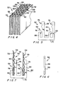
- a first embodiment of a film pack for cooling towers is generally indicated by the reference numeral 10.
- the film pack 10 includes a plurality of planar asbestos cement sheet elements 12 spaced apart from one another by plastics sheet intermediate elements 14.
- the sheet elements 12 are substantially vertically disposed whereas the intermediate elements 14 are provided with primary corrugations 16, which are also vertically disposed, and the amplitude of which determines the spacing between adjacent sheet elements 12.
- the intermediate elements 14 are further provided with axillary corrugations 18 which are disposed orthogonally with respect to the primary corrugations 16 and which have a subostantially smaller amplitude than the primary corrugations 16.
- the intermediate elements are substantially rigid, particularly in a direction perpendicular to the plane of the plastics sheet, intermediate spacer elements 14.
- the intermediate elements define a plurality of apices 20 providing point contact between the sheet elements 12 and intermediate elements 14.
- the sheet elements 12 and intermediate elements 14 are secured to one another by one or more wire elements 22 which clip onto the sheet elements 12 and intermediate elements 14 as is particularly shown in Figure 2. In this way a rigid film pack of any required size and incorporating any required number of sheet elements 12 can be provided.
- a modified intermediate element 14.1 also includes primary corrugations 16 and auxiliary corrugations 18.
- the primary corrugations define corrugated paths 23 with respect to the median plane of the intermediate elements. This provides additional rigidity to these elements and also prevents any liquid droplets to drop straight through the pack 10 when sprayed onto the pack as is hereinafter described.
- the film pack 10 is installed into a cooling tower in the configuration shown. Heated liquid to be cooled, is sprayed onto the film pack 10 and forms a'liquid film on the surfaces of the sheet elements 12 and intermediate elements 14.
- the film of liquid flows downwardly along the surfaces of the sheet elements 12 and intermediate elements 14 under gravity and is cooled by air flow, which may be natural or induced, flowing vertically upwardly through the spaces defined between the sheet elements 12 by the corrugations 16 of the intermediate elements 14.
- air flow which may be natural or induced, flowing vertically upwardly through the spaces defined between the sheet elements 12 by the corrugations 16 of the intermediate elements 14.
- the auxiliary corrugations 18 will permit some airflow and liquid flow horizontally and in this way it is ensured that the flow of liquid and air is substantially constant throughout the entire film pack 10.
- the Provision of a plastics sheet intermediate element 14 between adjacent sheet elements 12 increases the surface area upon which a liquid film for cooling can form and thus the contact area between liquid and air.
- the corrugations 16 and 18 of the intermediate elements 14 further increases this area.
- the efficiency of a-pack 10 as described above is thus higher than that of a conventional pack of the same size not having intermediate elements 14, the increased contact area always being measured against increased air flow resistance to provide optimum efficiency.
- the abovementioned contact area can be further increased by providing corrugated sheet elements 30, corrugations of the sheet elements 30 being horizontally disposed as shown.
- the sheet elements are again spaced apart by plastics sheet intermediate elements 32.
- the intermediate elements 32 also have primary corrugations 16 and auxiliary corrugations 18 as described above but are additionally corrugated to be couplementary to the corrugated sheets 30 as shown.
- wire elements are not required as these elements locate themselves by means of their complementary corrugations. Only the opposing outer sheet elements of such a film pack need thus be located. '
- the intermediate elements 14, 32 may particularly be of P.V.C. sheeting which may be vacuum formed to define the required corrugations.
- the angle of the primary corrugations 16 where each intermediate element intersects its median plane clearly determines the spacing between. adjacent sheet elements and this angle may thus be varied between, for example, 30° and 60°. Preferably this angle may be 45°.
- resistance against air flow, as measured against contact area, through a film pack may be such as to provide optimum efficiency of the pack.
- the surface of the spacer elements and/or the sheet elements may be dimpled, the design of such dimples, as for that of the corrugations, being such that air flow resistance is minimised as far as is practically possible.
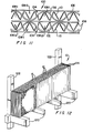
- a third embodiment of a film pack for cooling towers is generally indicated by the reference numeral 50.
- the pack 50 includes a plurality of planar asbestos sheet elements 52 spaced apart from one another by plastics sheet intermediate elements 54.
- the sheet elements 52 are substantially vertically disposed whereas the intermediate elements 54 are provided with primary corrugations 56 which are also vertically disposed, and the amplitude of which determines the spacing between adjacent sheet elements 52.
- the intermediate elements are further provided with auxilliary corrugations 58 which are disposed orthogonally with respect to the primary corrugations 56 and which have a substantially smaller amplitude than the primary corrugations 56: Having primary corrugations 56 and auxiliary corrugations 58 the intermediate elements are substantially rigid, particularly in a direction perpendicular to the plane of the plastics sheet, intermediate elements 54.
- the intermediate elements define a plurality of apices 60 providing point contacts between the sheet elements 52 and the intermediate elements 54.
- the sheet elements 52 and the intermediate elements 54 are secured to one another by a plurality of moulded plastics securing elements 62 which clip onto the sheet elements 52 and the intermediate elements 54 as is particularly shown in Figure 4. In this way a rigid film pack of any required size and incorporating any required number of sheet elements 12 can be provided.
- Each securing element 62 comprises two clip formations 64, each clip formation being defined by two opposing legs 62 and 68 respectively, projecting from a common base portion 70.
- the legs 66 and 68 of each clip formation 64 lie in a common plane and the spacing between the clip formations 64 is equal to the spacing between adjacent sheet elements 52.
- the securing elements 62 engage the sheet elements 52 and the intermediate elements 54 in the region of peaks 72 defined by the primary corrugations 56.
- each securing element 62 engages simultaneously two sheet elements 52 and the abutting intermediate elements 54 in the above described regions by means of the two clip formations respectively.
- the legs 66 of the clip formations 64 define serrated edges 74 which abut the sheet elements 52 whereas the legs 68 define corrugated edges 76 which abut the intermediate elements 54.
- the corrugated edges 76 are complimentary to the auxiliary corrugations 58 of the intermediate elements 54 and together with the serrated edges 74 and the proper spacing between the legs 66 and 68, it is ensured that the securing elements clip securely onto the sheets 52 and 54 so that the film pack 50 can be securely held together.
- the securing elements 62 can clip onto the sheets 52 and 54 in a pre-determined staggered configuration as shown, so that all the sheets 52 and 54 of a film pack 50 can thereby be securely held together.
- the securing elements 62 are further disposed at opposite ends of the pack 50, only those elements 62 on the top end of the pack being visible in Figure 4.
- the securing elements 62 may be of any suitable plastics material and may be formed in any suitable manner such as by moulding, pressing or the like. Typically, the elements 62 may be of P V C, polyethylene or polypropylene.
- a fourth embodiment of a film pack, in accordance with the invention is generally indicated by the reference numeral 80.
- the film pack 80 includes corrugated asbestos cement sheet elements 82, the corrugations 84 being vertically disposed in the operative configuration of the film pack 80.
- Adjacent sheet elements 82 are off-set with respect to one another so that the packs of one sheet element 82 abut the valleys of an adjacent sheet element 82 and vice versa.
- the sheet elements define spaces 86 between them, the spaces 86 having intermediate elements 88 disposed therein as shown.
- the intermediate elements 88 each define a vertically disposed primary, corrugation and auxiliary corrugations 92, orthogonal to the primary corrugation, an intermediate element as above described being shown in detail in Figure 9.
- the elements 88 are held in position by planer end regions 94 which are clamped between adjacent sheet elements 82 where they effectively abut.
- FIGs 10 and 11 show a fifth embodiment of a film pack, indicated by the numeral 100.
- the film pack 100 again, includes asbestos cement sheet elements 102, having corrugations 104 that are vertically disposed in the operative configuration of the film pack 100.
- additional planar asbestos cement sheet elements 106 are provided which are located between the elements 102, the elements 102 being effectively arranged as the elements 82 described with reference to Figures 8 and 9.
- Spaces 108 defined between the sheet elements 102 are now divided in half by the elements 106, providing half spaces 108.1 and 108.2.
- Each half space 108.1 and 108.2 has an intermediate element 110, disposed therein the elements 110 being equivalent to the element 88 described with reference to Figure 9 and being arranged in the spaces 108 in the configuration as is cleatly shown in Figure 11. In this configuration the intermediate elements 110 can be frictionally held in the spaces 108.
- FIG. 12 there is shown a film pack 10 supported in a typical configuration in a cooling tower, As shown the pack 10 is supported upon support beams 120 being horizontally disposed in a cooling tower, upright columns 122 providing for the pack 10 to remain in its upright configuration. Additional spacer members 124, are provided between the sheet elements 12 and thus clearly permit any intermediate elements 14 to be removed as may be required. This may be necessary since the effective life of the intermediate elements is significantly shorter than that of the asbestos cement elements 12 and by such replacement the life of a pack 10 can thus be extended.
- the spacer members 124 may be of plastics, asbestos cement or concrete and clearly, at least partially, fulfill the function of the intermediate elements 14 insofar as they space apart the sheet elements 12. Such spacer members may clearly also be used for packs 29 and 50 but will not be essential for packs 80 and 100 described above.
- the beams 120 and columns 122 may define a concrete framework in a cooling tower articularly disposed and adapted to support an entire film pack arrangement in such a tower.
- Film packs as above described are relatively economic to manufacture and construct and provide superior efficiency as compared with conventional packs not employing intermediate elements of a plastics sheet.
Priority Applications (1)
| Application Number | Priority Date | Filing Date | Title |
|---|---|---|---|
| AT81110227T ATE10029T1 (de) | 1980-12-08 | 1981-12-08 | Fuellkoerper fuer kuehltuerme. |
Applications Claiming Priority (4)
| Application Number | Priority Date | Filing Date | Title |
|---|---|---|---|
| ZA807676 | 1980-12-08 | ||
| ZA807676 | 1980-12-08 | ||
| ZA812114 | 1981-03-30 | ||
| ZA812114 | 1981-03-30 |
Publications (3)
| Publication Number | Publication Date |
|---|---|
| EP0053829A2 true EP0053829A2 (fr) | 1982-06-16 |
| EP0053829A3 EP0053829A3 (en) | 1982-10-27 |
| EP0053829B1 EP0053829B1 (fr) | 1984-10-24 |
Family
ID=27132639
Family Applications (1)
| Application Number | Title | Priority Date | Filing Date |
|---|---|---|---|
| EP81110227A Expired EP0053829B1 (fr) | 1980-12-08 | 1981-12-08 | Garniture pour tours de refroidissement |
Country Status (4)
| Country | Link |
|---|---|
| EP (1) | EP0053829B1 (fr) |
| DE (1) | DE3166869D1 (fr) |
| ES (1) | ES8301012A1 (fr) |
| GR (1) | GR76687B (fr) |
Cited By (3)
| Publication number | Priority date | Publication date | Assignee | Title |
|---|---|---|---|---|
| EP0070676A2 (fr) * | 1981-07-16 | 1983-01-26 | Film Cooling Towers Limited | Perfectionnements aux garnitures d'échange de chaleur |
| GB2258524A (en) * | 1991-08-08 | 1993-02-10 | Nat Power Plc | Film type packing element for use in cooling towers |
| EP1398593A3 (fr) * | 2002-09-13 | 2008-05-28 | Air Products And Chemicals, Inc. | Echangeur de chaleur à plaques et ailettes avec surfaces texturées |
Citations (10)
| Publication number | Priority date | Publication date | Assignee | Title |
|---|---|---|---|---|
| US1831533A (en) * | 1929-01-08 | 1931-11-10 | Babcock & Wilcox Co | Heat exchange device |
| US2759719A (en) * | 1952-05-02 | 1956-08-21 | Balcke Ag Maschbau | Cooling tower for liquids |
| US3084918A (en) * | 1960-04-21 | 1963-04-09 | Fluor Corp | Corrugated packing for counterflow cooling towers |
| GB1011035A (en) * | 1963-05-31 | 1965-11-24 | Turners Asbestos Cement Co | Improvements relating to packing of cooling towers and like apparatus |
| FR1479375A (fr) * | 1966-03-17 | 1967-05-05 | Perfectionnements aux appareils de réfrigération d'eau ou liquides analogues | |
| GB1106566A (en) * | 1964-03-24 | 1968-03-20 | Munters Carl Georg | An improved contact body or heat exchanger packing in a contact apparatus |
| US3395515A (en) * | 1964-03-16 | 1968-08-06 | William Stanley Lovely | Cooling towers |
| FR2263484A1 (fr) * | 1974-03-11 | 1975-10-03 | Baltimore Aircoil Co Inc | |
| DE2607312A1 (de) * | 1975-03-11 | 1976-09-23 | Svenska Flaektfabriken Ab | Vorrichtung zur befeuchtung von durch eine kammer stroemender luft |
| FR2386008A1 (fr) * | 1977-04-01 | 1978-10-27 | Svenska Flaektfabriken Ab | Corps de contact entre liquide et gaz, en particulier pour des humidificateurs d'air et des tours de refroidissement |
-
1981
- 1981-12-07 GR GR66718A patent/GR76687B/el unknown
- 1981-12-07 ES ES507772A patent/ES8301012A1/es not_active Expired
- 1981-12-08 DE DE8181110227T patent/DE3166869D1/de not_active Expired
- 1981-12-08 EP EP81110227A patent/EP0053829B1/fr not_active Expired
Patent Citations (10)
| Publication number | Priority date | Publication date | Assignee | Title |
|---|---|---|---|---|
| US1831533A (en) * | 1929-01-08 | 1931-11-10 | Babcock & Wilcox Co | Heat exchange device |
| US2759719A (en) * | 1952-05-02 | 1956-08-21 | Balcke Ag Maschbau | Cooling tower for liquids |
| US3084918A (en) * | 1960-04-21 | 1963-04-09 | Fluor Corp | Corrugated packing for counterflow cooling towers |
| GB1011035A (en) * | 1963-05-31 | 1965-11-24 | Turners Asbestos Cement Co | Improvements relating to packing of cooling towers and like apparatus |
| US3395515A (en) * | 1964-03-16 | 1968-08-06 | William Stanley Lovely | Cooling towers |
| GB1106566A (en) * | 1964-03-24 | 1968-03-20 | Munters Carl Georg | An improved contact body or heat exchanger packing in a contact apparatus |
| FR1479375A (fr) * | 1966-03-17 | 1967-05-05 | Perfectionnements aux appareils de réfrigération d'eau ou liquides analogues | |
| FR2263484A1 (fr) * | 1974-03-11 | 1975-10-03 | Baltimore Aircoil Co Inc | |
| DE2607312A1 (de) * | 1975-03-11 | 1976-09-23 | Svenska Flaektfabriken Ab | Vorrichtung zur befeuchtung von durch eine kammer stroemender luft |
| FR2386008A1 (fr) * | 1977-04-01 | 1978-10-27 | Svenska Flaektfabriken Ab | Corps de contact entre liquide et gaz, en particulier pour des humidificateurs d'air et des tours de refroidissement |
Cited By (7)
| Publication number | Priority date | Publication date | Assignee | Title |
|---|---|---|---|---|
| EP0070676A2 (fr) * | 1981-07-16 | 1983-01-26 | Film Cooling Towers Limited | Perfectionnements aux garnitures d'échange de chaleur |
| EP0070676B1 (fr) * | 1981-07-16 | 1988-05-04 | Film Cooling Towers Limited | Perfectionnements aux garnitures d'échange de chaleur |
| GB2258524A (en) * | 1991-08-08 | 1993-02-10 | Nat Power Plc | Film type packing element for use in cooling towers |
| GB2258524B (en) * | 1991-08-08 | 1995-05-31 | Nat Power Plc | Film type packing element for use in cooling towers |
| US5474832A (en) * | 1991-08-08 | 1995-12-12 | National Power Plc | Film type packing element for use in cooling towers |
| EP1398593A3 (fr) * | 2002-09-13 | 2008-05-28 | Air Products And Chemicals, Inc. | Echangeur de chaleur à plaques et ailettes avec surfaces texturées |
| EP1398593B1 (fr) | 2002-09-13 | 2016-02-03 | Air Products And Chemicals, Inc. | Echangeur de chaleur à plaques et ailettes avec surfaces texturées |
Also Published As
| Publication number | Publication date |
|---|---|
| ES507772A0 (es) | 1982-11-01 |
| GR76687B (fr) | 1984-08-24 |
| EP0053829A3 (en) | 1982-10-27 |
| EP0053829B1 (fr) | 1984-10-24 |
| DE3166869D1 (en) | 1984-11-29 |
| ES8301012A1 (es) | 1982-11-01 |
Similar Documents
| Publication | Publication Date | Title |
|---|---|---|
| US5217788A (en) | Corrugated sheet assembly | |
| EP0671963B1 (fr) | Garnissage a emboitement pour colonne echangeuse | |
| US4668443A (en) | Contact bodies | |
| EP1004839B1 (fr) | Elément de garnissage à écoulement en film, avec circulation en tourbillons du gaz pour appareil de contact à échange de masse et de chaleur comprenant des feuilles de ruissellement avec distanceurs | |
| US4361426A (en) | Angularly grooved corrugated fill for water cooling tower | |
| JPS60243495A (ja) | 水用クーリングタワーのためのフイルム装填シートおよびフイルム装填パツク | |
| US3652066A (en) | Packing for a cooling tower | |
| US4579693A (en) | Liquid/gas contact means | |
| KR900004394A (ko) | 공기유도 간격자들을 구비한 물 냉각탑용 플라스틱 침투시이트 | |
| JPH01180203A (ja) | 向流する気体−液体接触設備における充填装置用滴下シート該滴下シート用帯体及び該滴下シートにより構成された充填装置 | |
| AU6064899A (en) | Film fill-pack for inducement of spiraling gas flow in heat and mass transfer contact apparatus with self-spacing fill-sheets | |
| US5204027A (en) | Fluid contact panels | |
| EP0053829A2 (fr) | Garniture pour tours de refroidissement | |
| AU766548B2 (en) | Film fill-pack for inducement of spiraling gas flow in heat and mass transfer contact apparatus with self-spacing fill-sheets | |
| JPH0319478B2 (fr) | ||
| US4579694A (en) | Wet deck fill | |
| US20190226693A1 (en) | Insert element for inserting into a device for humidifying, cleaning and/or cooling a fluid, in particular a gas, such as, for example, air | |
| SK76294A3 (en) | Filling for evaporative cooler and method of its construction | |
| GB1587388A (en) | Clips | |
| JPH0534089A (ja) | 熱交換エレメント | |
| CN217042615U (zh) | 一种高强度聚合体填料 | |
| CN116829895A (zh) | 科技清洁直接热交换填料 | |
| JP2024508100A (ja) | テッククリーン(techclean)(登録商標)直接熱交換型充填材 | |
| RU22704U1 (ru) | Ороситель градирни | |
| JPH01171602A (ja) | プレート式流下液膜蒸発装置用伝熱プレートエレメント |
Legal Events
| Date | Code | Title | Description |
|---|---|---|---|
| PUAI | Public reference made under article 153(3) epc to a published international application that has entered the european phase |
Free format text: ORIGINAL CODE: 0009012 |
|
| AK | Designated contracting states |
Designated state(s): AT BE CH DE FR GB IT LU NL SE |
|
| PUAL | Search report despatched |
Free format text: ORIGINAL CODE: 0009013 |
|
| AK | Designated contracting states |
Designated state(s): AT BE CH DE FR GB IT LU NL SE |
|
| 17P | Request for examination filed |
Effective date: 19821215 |
|
| ITF | It: translation for a ep patent filed |
Owner name: BARZANO' E ZANARDO MILANO S.P.A. |
|
| GRAA | (expected) grant |
Free format text: ORIGINAL CODE: 0009210 |
|
| AK | Designated contracting states |
Designated state(s): AT BE CH DE FR GB IT LI LU NL SE |
|
| PG25 | Lapsed in a contracting state [announced via postgrant information from national office to epo] |
Ref country code: SE Effective date: 19841024 Ref country code: NL Effective date: 19841024 |
|
| REF | Corresponds to: |
Ref document number: 10029 Country of ref document: AT Date of ref document: 19841115 Kind code of ref document: T |
|
| REF | Corresponds to: |
Ref document number: 3166869 Country of ref document: DE Date of ref document: 19841129 |
|
| PGFP | Annual fee paid to national office [announced via postgrant information from national office to epo] |
Ref country code: CH Payment date: 19841205 Year of fee payment: 4 |
|
| PGFP | Annual fee paid to national office [announced via postgrant information from national office to epo] |
Ref country code: FR Payment date: 19841206 Year of fee payment: 4 |
|
| ET | Fr: translation filed | ||
| PG25 | Lapsed in a contracting state [announced via postgrant information from national office to epo] |
Ref country code: LU Free format text: LAPSE BECAUSE OF NON-PAYMENT OF DUE FEES Effective date: 19841231 |
|
| PGFP | Annual fee paid to national office [announced via postgrant information from national office to epo] |
Ref country code: BE Payment date: 19841231 Year of fee payment: 4 |
|
| NLV1 | Nl: lapsed or annulled due to failure to fulfill the requirements of art. 29p and 29m of the patents act | ||
| PLBE | No opposition filed within time limit |
Free format text: ORIGINAL CODE: 0009261 |
|
| STAA | Information on the status of an ep patent application or granted ep patent |
Free format text: STATUS: NO OPPOSITION FILED WITHIN TIME LIMIT |
|
| 26N | No opposition filed | ||
| PGFP | Annual fee paid to national office [announced via postgrant information from national office to epo] |
Ref country code: AT Payment date: 19861128 Year of fee payment: 6 |
|
| PGFP | Annual fee paid to national office [announced via postgrant information from national office to epo] |
Ref country code: DE Payment date: 19890126 Year of fee payment: 8 |
|
| PG25 | Lapsed in a contracting state [announced via postgrant information from national office to epo] |
Ref country code: GB Effective date: 19891208 Ref country code: AT Effective date: 19891208 |
|
| PG25 | Lapsed in a contracting state [announced via postgrant information from national office to epo] |
Ref country code: LI Effective date: 19891231 Ref country code: CH Effective date: 19891231 Ref country code: BE Effective date: 19891231 |
|
| BERE | Be: lapsed |
Owner name: WLPU HOLDINGS (PROPRIETARY) LTD Effective date: 19891231 |
|
| GBPC | Gb: european patent ceased through non-payment of renewal fee | ||
| PG25 | Lapsed in a contracting state [announced via postgrant information from national office to epo] |
Ref country code: FR Effective date: 19900831 |
|
| REG | Reference to a national code |
Ref country code: CH Ref legal event code: PL |
|
| PG25 | Lapsed in a contracting state [announced via postgrant information from national office to epo] |
Ref country code: DE Effective date: 19900901 |
|
| REG | Reference to a national code |
Ref country code: FR Ref legal event code: ST |
|
| REG | Reference to a national code |
Ref country code: CH Ref legal event code: AUV Free format text: DAS OBENGENANNTE PATENT IST, MANGELS BEZAHLUNG DER 9.JAHRESGEBUEHR GELOESCHT WORDEN. |