EP0053552A1 - Reaktorgebäude mit Kesselbehälter, dessen Rand mittels einer Betonplatte fixiert ist - Google Patents
Reaktorgebäude mit Kesselbehälter, dessen Rand mittels einer Betonplatte fixiert ist Download PDFInfo
- Publication number
- EP0053552A1 EP0053552A1 EP81401877A EP81401877A EP0053552A1 EP 0053552 A1 EP0053552 A1 EP 0053552A1 EP 81401877 A EP81401877 A EP 81401877A EP 81401877 A EP81401877 A EP 81401877A EP 0053552 A1 EP0053552 A1 EP 0053552A1
- Authority
- EP
- European Patent Office
- Prior art keywords
- slab
- internal structures
- raft
- buton
- reactor building
- Prior art date
- Legal status (The legal status is an assumption and is not a legal conclusion. Google has not performed a legal analysis and makes no representation as to the accuracy of the status listed.)
- Granted
Links
- 239000012791 sliding layer Substances 0.000 claims description 9
- WDECIBYCCFPHNR-UHFFFAOYSA-N chrysene Chemical compound C1=CC=CC2=CC=C3C4=CC=CC=C4C=CC3=C21 WDECIBYCCFPHNR-UHFFFAOYSA-N 0.000 claims description 6
- 239000011083 cement mortar Substances 0.000 claims description 4
- 239000003921 oil Substances 0.000 claims description 3
- 229920000915 polyvinyl chloride Polymers 0.000 claims description 3
- 239000004800 polyvinyl chloride Substances 0.000 claims description 3
- 239000004793 Polystyrene Substances 0.000 claims description 2
- 229920001971 elastomer Polymers 0.000 claims description 2
- 239000000806 elastomer Substances 0.000 claims description 2
- 239000002184 metal Substances 0.000 claims description 2
- 229920002223 polystyrene Polymers 0.000 claims description 2
- 230000000630 rising effect Effects 0.000 claims description 2
- 125000000391 vinyl group Chemical group [H]C([*])=C([H])[H] 0.000 claims description 2
- 229920002554 vinyl polymer Polymers 0.000 claims description 2
- 239000011248 coating agent Substances 0.000 description 6
- 238000000576 coating method Methods 0.000 description 6
- 230000000903 blocking effect Effects 0.000 description 4
- 229910001209 Low-carbon steel Inorganic materials 0.000 description 3
- PPBRXRYQALVLMV-UHFFFAOYSA-N Styrene Chemical compound C=CC1=CC=CC=C1 PPBRXRYQALVLMV-UHFFFAOYSA-N 0.000 description 2
- 238000006073 displacement reaction Methods 0.000 description 2
- 238000004519 manufacturing process Methods 0.000 description 2
- 239000000463 material Substances 0.000 description 2
- 238000007789 sealing Methods 0.000 description 2
- 238000004873 anchoring Methods 0.000 description 1
- 238000006243 chemical reaction Methods 0.000 description 1
- 230000000295 complement effect Effects 0.000 description 1
- 238000010276 construction Methods 0.000 description 1
- 230000000694 effects Effects 0.000 description 1
- 238000010438 heat treatment Methods 0.000 description 1
- 239000010410 layer Substances 0.000 description 1
- 230000001681 protective effect Effects 0.000 description 1
- 239000012857 radioactive material Substances 0.000 description 1
Images

Classifications
-
- G—PHYSICS
- G21—NUCLEAR PHYSICS; NUCLEAR ENGINEERING
- G21C—NUCLEAR REACTORS
- G21C13/00—Pressure vessels; Containment vessels; Containment in general
-
- G—PHYSICS
- G21—NUCLEAR PHYSICS; NUCLEAR ENGINEERING
- G21C—NUCLEAR REACTORS
- G21C19/00—Arrangements for treating, for handling, or for facilitating the handling of, fuel or other materials which are used within the reactor, e.g. within its pressure vessel
- G21C19/32—Apparatus for removing radioactive objects or materials from the reactor discharge area, e.g. to a storage place; Apparatus for handling radioactive objects or materials within a storage place or removing them therefrom
-
- Y—GENERAL TAGGING OF NEW TECHNOLOGICAL DEVELOPMENTS; GENERAL TAGGING OF CROSS-SECTIONAL TECHNOLOGIES SPANNING OVER SEVERAL SECTIONS OF THE IPC; TECHNICAL SUBJECTS COVERED BY FORMER USPC CROSS-REFERENCE ART COLLECTIONS [XRACs] AND DIGESTS
- Y02—TECHNOLOGIES OR APPLICATIONS FOR MITIGATION OR ADAPTATION AGAINST CLIMATE CHANGE
- Y02E—REDUCTION OF GREENHOUSE GAS [GHG] EMISSIONS, RELATED TO ENERGY GENERATION, TRANSMISSION OR DISTRIBUTION
- Y02E30/00—Energy generation of nuclear origin
- Y02E30/30—Nuclear fission reactors
Definitions
- the present invention relates to a reactor building which comprises a device ensuring the positioning of the internal structures while allowing their free thermal expansion.
- the building in which a nuclear reactor is installed is constituted by a confinement enclosure inside which structures, called internal structures, are arranged, which support the components of the primary circuit.
- These structures essentially comprise a raft called the raft of internal structures, a structure called vessel well surrounding and supporting the reactor vessel and casemates located around the vessel well.
- the purpose of the containment is to prevent any leakage of radioactive material in the event of an accident and to resist the effects of pressure and temperature resulting from a possible rupture of the primary or secondary circuits.
- the containment is constituted by a raft called general raft, by a cylindrical skirt which rises on the general raft, and by a dome which closes the cylindrical skirt at its upper part.
- the containment is sealed by a mild steel metallic coating, also called skin.
- Reactor buildings are known in which the blocking of the internal structures relative to the general raft is obtained by clamping the base of the tank well by means of mechanical stops. These mechanical stops are anchored in a concrete slab which rests on the general raft.
- the concrete slab has a recess in the central part of its underside.
- a circular boss of complementary shape made in the general raft engages in the recess of the concrete slab.
- the blocking of the slab is thus obtained relative to the general raft and consequently, the blocking of the vessel well and of the internal structures relative to the general raft.
- the containment is sealed by a mild steel metallic coating. This coating follows the detachment of the boss made in the general raft. This system is a complex achievement. On the other hand, it makes the production of the waterproof coating much more delicate.
- the present invention relates to a reactor building which overcomes these drawbacks.
- the internal structures are positioned relative to the enclosure by anchoring the vessel well in a slab blocked at its periphery against the confinement enclosure.
- the reactor building according to the invention constituted by a confinement enclosure inside which internal structures are positioned, the confinement enclosure consisting of a cylindrical skirt closed at its upper part by a dome and rising on a raft known as general raft, the internal structures consisting of a raft called raft internal structures, of a concrete cylinder said well of tank located substantially in the center of the raft of internal structures and casemates surrounding the well of tank, is characterized in that the cylindrical skirt is connected to the general raft by a lower part by determining a cuvet te with a flat bottom in which said internal structures are positioned, a so-called buton slab being disposed between the general slab and the slab of the internal structures, the vessel well being anchored in the slab, the buton slab being blocked at its periphery against the lower part of the skirt, a horizontal joint constituted by a sliding product being arranged in a crown from the well of the tank between the buton slab and the raft from the internal structures.
- the sliding layer is produced by means of polyvinyl chloride sheets gelled with chrysene oils and plasticized. Its mechanical protection, during the realization of the raft of the internal structures is ensured by a screed not reinforced with cement mortar.
- the sliding layer allows free expansion from the well of the raft of the internal structures relative to the slab of struts.
- the sliding layer may by itself have sufficient strength to support the floor of the internal structures. According to an alternative embodiment, it is also possible to provide supports arranged at the periphery of the buton slab, between the latter and the floor of the internal structures, which makes it possible to use for the sliding layer a material with lower mechanical characteristics.
- FIG. 1 a sectional view of the assembly of a nuclear reactor building.
- the vessel 2 of the nuclear reactor is disposed inside a confinement enclosure designated by the general reference 4.
- This enclosure consists of a cylindrical skirt 6, a slab 8, called general slab, and a dome (not shown) which closes the enclosure at its upper part.
- the tightness of the confinement enclosure 4 is ensured by a metallic coating 10 made of mild steel also called skin.
- the lower part of the cylinder skirt 6 is connected to the general raft 8.
- This connection can take the form of a frustoconical gusset 12 as shown in FIGS. 1 and 2, but can also be of cylindrical shape.
- a flat-bottomed bowl is thus determined inside which the internal structures are positioned.
- the part of the covering 10 disposed on the general raft 8 thus exhibits no drop in level.
- the internal concrete structures, designated by the reference 14 are located in the confinement enclosure 4 and serve mainly as support for the components of the primary circuit. They consist a slab 16, said to scour internal structures, a concrete cylinder 18 said well of support vessel of the tank 2 of the reactor, and located substantially in the center of the slab of internal structures 16, and casemates 20 arranged so radiant with respect to the tank well 18 of which they are integral.
- the internal structures are separated from the confinement enclosure 4 and a seal 5 made of styrene or a similar material prevails between the enclosure 4 and the upper facing of the raft of the internal structures 16.
- a slab 22 known as a buton slab is disposed between the general raft 8 and the slab of the internal structures 16. The buton slab 22 is blocked at its periphery against the gusset 12 of the confinement enclosure 4.
- the role of the buton slab 22 is to avoid, in the event of an earthquake, any relative horizontal displacement between the slab of the internal structures and the general slab.
- a horizontal joint 24 consisting of a product sliding is arranged in a crown from the tank well 18 between the buton slab 22 and this slab.
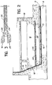
- FIG. 2 shows a partial sectional view of the reactor building shown in FIG. 1.
- Channels 13 embedded in a layer of protective concrete 11 make it possible to control the welds of the sealing skin 10.
- the sliding layer 24 is arranged in a crown from the well 18 between the buton slab 22 and the slab of the internal structures 16.
- This sliding layer can be produced by means polyvinyl chloride sheets gelled with chrysene oils and plasticized.
- a screed 26 not reinforced with cement mortar, poured over the sliding layer 24, provides its mechanical protection during the production of the raft of the internal structures 16.
- the hot part of the buton slab 22 located to the right of the well 18 has a relatively small average diameter compared to the contact diameter between the buton slab 22 and the gusset 12.
- the thickness of the buton slab 22 is as reduced as possible within the limit allowed by the seismic forces to be transmitted.
- the horizontal sliding joint 24 can have sufficient mechanical strength by itself, but supports 28 can also be inserted between the slab 22 and the floor of the internal structures 16, as shown, in the variant of FIG. 3.
- These supports while allowing the relative horizontal movement of the internal structures 14 with respect to the buton slab 22., have the advantage of ensuring precise positioning of the support reactions of the raft of the internal structures 16 on the buton slab 22 and on the general raft 8; to improve the earthquake stability of the internal structures 14, and to use a sliding product with lower mechanical characteristics, for example polystyrene with vinyl protection.
- the supports 28 are sliding metal supports arranged at the periphery of the buton slab 22. According to an alternative embodiment, the supports 28 are made of hooped elastomer.
Landscapes
- Physics & Mathematics (AREA)
- Engineering & Computer Science (AREA)
- Plasma & Fusion (AREA)
- General Engineering & Computer Science (AREA)
- High Energy & Nuclear Physics (AREA)
- Buildings Adapted To Withstand Abnormal External Influences (AREA)
- Structure Of Emergency Protection For Nuclear Reactors (AREA)
- Building Environments (AREA)
- Production Of Liquid Hydrocarbon Mixture For Refining Petroleum (AREA)
Applications Claiming Priority (2)
| Application Number | Priority Date | Filing Date | Title |
|---|---|---|---|
| FR8025304 | 1980-11-28 | ||
| FR8025304A FR2495370B1 (fr) | 1980-11-28 | 1980-11-28 | Batiment reacteur comportant un puits de cuve ancre dans une dalle bloquee a sa peripherie |
Publications (2)
| Publication Number | Publication Date |
|---|---|
| EP0053552A1 true EP0053552A1 (de) | 1982-06-09 |
| EP0053552B1 EP0053552B1 (de) | 1985-04-03 |
Family
ID=9248461
Family Applications (1)
| Application Number | Title | Priority Date | Filing Date |
|---|---|---|---|
| EP81401877A Expired EP0053552B1 (de) | 1980-11-28 | 1981-11-26 | Reaktorgebäude mit Kesselbehälter, dessen Rand mittels einer Betonplatte fixiert ist |
Country Status (13)
| Country | Link |
|---|---|
| US (1) | US4472349A (de) |
| EP (1) | EP0053552B1 (de) |
| JP (1) | JPS57119293A (de) |
| KR (1) | KR880002049B1 (de) |
| DE (1) | DE3169743D1 (de) |
| EG (1) | EG16615A (de) |
| ES (1) | ES507525A0 (de) |
| FI (1) | FI71849C (de) |
| FR (1) | FR2495370B1 (de) |
| GR (1) | GR78025B (de) |
| MA (1) | MA19341A1 (de) |
| PT (1) | PT74007B (de) |
| YU (1) | YU42001B (de) |
Families Citing this family (1)
| Publication number | Priority date | Publication date | Assignee | Title |
|---|---|---|---|---|
| EP0265697B1 (de) * | 1986-10-13 | 1993-04-07 | Siemens Aktiengesellschaft | Bauwerk mit radioaktiven Anlageteilen |
Citations (3)
| Publication number | Priority date | Publication date | Assignee | Title |
|---|---|---|---|---|
| GB1084064A (de) * | 1900-01-01 | |||
| DE1965850A1 (de) * | 1969-12-31 | 1971-07-08 | Siemens Ag | Deckelabdichtung fuer Spannbeton-Druckbehaelter |
| FR2427446A1 (fr) * | 1978-05-31 | 1979-12-28 | Freyssinet Int Stup | Dispositif amortisseur d'effets sismiques pour constructions |
Family Cites Families (5)
| Publication number | Priority date | Publication date | Assignee | Title |
|---|---|---|---|---|
| US3454466A (en) * | 1967-12-29 | 1969-07-08 | Atomic Energy Commission | Nuclear reactor containment system for metropolitan sites |
| US3605362A (en) * | 1969-06-10 | 1971-09-20 | Stone & Webster Eng Corp | Connection system for relieving stress in concrete structures |
| DE2052335C3 (de) * | 1970-10-24 | 1979-08-30 | Interatom Internationale Atomreaktorbau Gmbh, 5060 Bergisch Gladbach | Sicherheitsbehältersystem für natriumgekfihlte Kernreaktoren |
| DE2320201A1 (de) * | 1973-04-19 | 1974-11-07 | Siemens Ag | Kernkraftwerk |
| DE2328556A1 (de) * | 1973-06-05 | 1975-01-02 | Kraftwerk Union Ag | Waermetauscheranordnung fuer einen geschlossenen gaskreislauf z.b. einer waermekraftanlage |
-
1980
- 1980-11-28 FR FR8025304A patent/FR2495370B1/fr not_active Expired
-
1981
- 1981-11-17 US US06/322,387 patent/US4472349A/en not_active Expired - Fee Related
- 1981-11-17 GR GR66549A patent/GR78025B/el unknown
- 1981-11-18 PT PT74007A patent/PT74007B/pt not_active IP Right Cessation
- 1981-11-25 YU YU2763/81A patent/YU42001B/xx unknown
- 1981-11-26 DE DE8181401877T patent/DE3169743D1/de not_active Expired
- 1981-11-26 EP EP81401877A patent/EP0053552B1/de not_active Expired
- 1981-11-27 FI FI813818A patent/FI71849C/fi not_active IP Right Cessation
- 1981-11-27 MA MA19545A patent/MA19341A1/fr unknown
- 1981-11-27 ES ES507525A patent/ES507525A0/es active Granted
- 1981-11-27 KR KR1019810004598A patent/KR880002049B1/ko not_active Expired
- 1981-11-27 JP JP56190474A patent/JPS57119293A/ja active Granted
- 1981-11-28 EG EG698/81A patent/EG16615A/xx active
Patent Citations (3)
| Publication number | Priority date | Publication date | Assignee | Title |
|---|---|---|---|---|
| GB1084064A (de) * | 1900-01-01 | |||
| DE1965850A1 (de) * | 1969-12-31 | 1971-07-08 | Siemens Ag | Deckelabdichtung fuer Spannbeton-Druckbehaelter |
| FR2427446A1 (fr) * | 1978-05-31 | 1979-12-28 | Freyssinet Int Stup | Dispositif amortisseur d'effets sismiques pour constructions |
Also Published As
| Publication number | Publication date |
|---|---|
| US4472349A (en) | 1984-09-18 |
| KR880002049B1 (ko) | 1988-10-13 |
| EP0053552B1 (de) | 1985-04-03 |
| EG16615A (en) | 1993-07-30 |
| KR830008342A (ko) | 1983-11-18 |
| PT74007A (fr) | 1981-12-01 |
| FI71849C (fi) | 1987-02-09 |
| PT74007B (fr) | 1983-03-31 |
| FR2495370A1 (fr) | 1982-06-04 |
| FI71849B (fi) | 1986-10-31 |
| GR78025B (de) | 1984-09-26 |
| FI813818L (fi) | 1982-05-29 |
| FR2495370B1 (fr) | 1985-12-06 |
| MA19341A1 (fr) | 1982-07-01 |
| YU276381A (en) | 1984-02-29 |
| YU42001B (en) | 1988-04-30 |
| JPH0225474B2 (de) | 1990-06-04 |
| JPS57119293A (en) | 1982-07-24 |
| ES8600551A1 (es) | 1985-10-01 |
| DE3169743D1 (en) | 1985-05-09 |
| ES507525A0 (es) | 1985-10-01 |
Similar Documents
| Publication | Publication Date | Title |
|---|---|---|
| EP0267134B1 (de) | Schachtabdeckung | |
| FR2533960A1 (fr) | Structure de protection du plancher d'une enceinte de beton | |
| EP0388253B1 (de) | Belade- und Sicherheitswasservorlagebecken für einen Druckwasserkernreaktor | |
| EP0053552A1 (de) | Reaktorgebäude mit Kesselbehälter, dessen Rand mittels einer Betonplatte fixiert ist | |
| US3540740A (en) | Sealing means for plug valve stems | |
| FR2460026A1 (fr) | Dispositif collecteur pour les elements combustibles entrant en fusion d'un reacteur nucleaire | |
| FR2484056A1 (fr) | Joint flexible de coin pour recipient cryogenique | |
| FR2505980A1 (fr) | Perfectionnements aux couvercles pour reservoirs sous pression | |
| EP0058583B1 (de) | Mit flüssigem Metall gekühlter Kernreaktor, dessen Deckel Hohlräume aufweist | |
| EP0053553B1 (de) | Reaktorgebäude mit inneren Strukturen, deren Beanspruchung unabhängig von der Formveränderung der Betonplatte sind, und Verfahren zum Herstellen dieser Strukturen | |
| EP0156689B1 (de) | Schneller Kernreaktor mit hängendem Hauptbecken und Deckel | |
| US4696790A (en) | Prestressed concrete pressure vessel, in particular for a nuclear reactor installation | |
| EP0021919B1 (de) | Vorrichtung zum Befestigen und Abdichten von Kühlplatten am Hochofen | |
| EP0130911B1 (de) | Abdichtungsanordnung für drehbare Deckelverschlüsse eines Kernreaktors | |
| FR2555284A1 (fr) | Joint etanche et dispositif de raccordement pour des canalisations, notamment sur des installations de voirie | |
| US4106759A (en) | Device and method for the introduction of gases into reaction vessels containing liquids | |
| FR2542908A1 (fr) | Perfectionnements aux puits de reacteur nucleaire pour limiter les consequences d'une perte de fluide de refroidissement | |
| FR2615928A1 (fr) | Procede et installation destines a la mise en place d'une cuve de stockage de gaz sous pression, ainsi que la cuve adaptee | |
| CA2099807A1 (fr) | Four, notamment four electrique, de traitement de metal liquide | |
| FR2563323A1 (fr) | Disposi | |
| FR2680597A1 (fr) | Structure interne d'un reacteur nucleaire a neutrons rapides. | |
| SU1547945A1 (ru) | Контейнер-ковш дл хранени и транспортировки жидкого металла, преимущественно алюмини | |
| EP0456313B1 (de) | Sicherheitsventil, insbesondere für die Entlüftungskanalisation eines Kraftstoffbehälters | |
| FR2602531A1 (fr) | Systeme d'evier-vidoir comprenant un evier et une cuve en dessous de celui-ci | |
| JPS6020080Y2 (ja) | 燃料プ−ル用ゲ−ト |
Legal Events
| Date | Code | Title | Description |
|---|---|---|---|
| PUAI | Public reference made under article 153(3) epc to a published international application that has entered the european phase |
Free format text: ORIGINAL CODE: 0009012 |
|
| AK | Designated contracting states |
Designated state(s): BE CH DE FR GB IT |
|
| 17P | Request for examination filed |
Effective date: 19821110 |
|
| ITF | It: translation for a ep patent filed | ||
| GRAA | (expected) grant |
Free format text: ORIGINAL CODE: 0009210 |
|
| AK | Designated contracting states |
Designated state(s): BE CH DE FR GB IT LI |
|
| REF | Corresponds to: |
Ref document number: 3169743 Country of ref document: DE Date of ref document: 19850509 |
|
| PLBE | No opposition filed within time limit |
Free format text: ORIGINAL CODE: 0009261 |
|
| STAA | Information on the status of an ep patent application or granted ep patent |
Free format text: STATUS: NO OPPOSITION FILED WITHIN TIME LIMIT |
|
| 26N | No opposition filed | ||
| ITTA | It: last paid annual fee | ||
| PGFP | Annual fee paid to national office [announced via postgrant information from national office to epo] |
Ref country code: BE Payment date: 19941031 Year of fee payment: 14 |
|
| PGFP | Annual fee paid to national office [announced via postgrant information from national office to epo] |
Ref country code: DE Payment date: 19941102 Year of fee payment: 14 |
|
| PGFP | Annual fee paid to national office [announced via postgrant information from national office to epo] |
Ref country code: GB Payment date: 19941111 Year of fee payment: 14 |
|
| PGFP | Annual fee paid to national office [announced via postgrant information from national office to epo] |
Ref country code: CH Payment date: 19941114 Year of fee payment: 14 |
|
| PGFP | Annual fee paid to national office [announced via postgrant information from national office to epo] |
Ref country code: FR Payment date: 19941129 Year of fee payment: 14 |
|
| PG25 | Lapsed in a contracting state [announced via postgrant information from national office to epo] |
Ref country code: GB Effective date: 19951126 |
|
| PG25 | Lapsed in a contracting state [announced via postgrant information from national office to epo] |
Ref country code: LI Effective date: 19951130 Ref country code: CH Effective date: 19951130 Ref country code: BE Effective date: 19951130 |
|
| BERE | Be: lapsed |
Owner name: FRAMATOME Effective date: 19951130 |
|
| REG | Reference to a national code |
Ref country code: CH Ref legal event code: PL |
|
| GBPC | Gb: european patent ceased through non-payment of renewal fee |
Effective date: 19951126 |
|
| PG25 | Lapsed in a contracting state [announced via postgrant information from national office to epo] |
Ref country code: FR Effective date: 19960731 |
|
| PG25 | Lapsed in a contracting state [announced via postgrant information from national office to epo] |
Ref country code: DE Effective date: 19960801 |
|
| REG | Reference to a national code |
Ref country code: FR Ref legal event code: ST |