EP0053514A1 - Kombiniertes Ventil - Google Patents
Kombiniertes Ventil Download PDFInfo
- Publication number
- EP0053514A1 EP0053514A1 EP19810305661 EP81305661A EP0053514A1 EP 0053514 A1 EP0053514 A1 EP 0053514A1 EP 19810305661 EP19810305661 EP 19810305661 EP 81305661 A EP81305661 A EP 81305661A EP 0053514 A1 EP0053514 A1 EP 0053514A1
- Authority
- EP
- European Patent Office
- Prior art keywords
- valve
- steam
- stop
- combined
- reheating
- Prior art date
- Legal status (The legal status is an assumption and is not a legal conclusion. Google has not performed a legal analysis and makes no representation as to the accuracy of the status listed.)
- Granted
Links
Images


Classifications
-
- F—MECHANICAL ENGINEERING; LIGHTING; HEATING; WEAPONS; BLASTING
- F16—ENGINEERING ELEMENTS AND UNITS; GENERAL MEASURES FOR PRODUCING AND MAINTAINING EFFECTIVE FUNCTIONING OF MACHINES OR INSTALLATIONS; THERMAL INSULATION IN GENERAL
- F16K—VALVES; TAPS; COCKS; ACTUATING-FLOATS; DEVICES FOR VENTING OR AERATING
- F16K39/00—Devices for relieving the pressure on the sealing faces
- F16K39/02—Devices for relieving the pressure on the sealing faces for lift valves
- F16K39/024—Devices for relieving the pressure on the sealing faces for lift valves using an auxiliary valve on the main valve
-
- F—MECHANICAL ENGINEERING; LIGHTING; HEATING; WEAPONS; BLASTING
- F01—MACHINES OR ENGINES IN GENERAL; ENGINE PLANTS IN GENERAL; STEAM ENGINES
- F01D—NON-POSITIVE DISPLACEMENT MACHINES OR ENGINES, e.g. STEAM TURBINES
- F01D17/00—Regulating or controlling by varying flow
- F01D17/10—Final actuators
- F01D17/12—Final actuators arranged in stator parts
- F01D17/14—Final actuators arranged in stator parts varying effective cross-sectional area of nozzles or guide conduits
- F01D17/141—Final actuators arranged in stator parts varying effective cross-sectional area of nozzles or guide conduits by means of shiftable members or valves obturating part of the flow path
- F01D17/145—Final actuators arranged in stator parts varying effective cross-sectional area of nozzles or guide conduits by means of shiftable members or valves obturating part of the flow path by means of valves, e.g. for steam turbines
-
- Y—GENERAL TAGGING OF NEW TECHNOLOGICAL DEVELOPMENTS; GENERAL TAGGING OF CROSS-SECTIONAL TECHNOLOGIES SPANNING OVER SEVERAL SECTIONS OF THE IPC; TECHNICAL SUBJECTS COVERED BY FORMER USPC CROSS-REFERENCE ART COLLECTIONS [XRACs] AND DIGESTS
- Y10—TECHNICAL SUBJECTS COVERED BY FORMER USPC
- Y10T—TECHNICAL SUBJECTS COVERED BY FORMER US CLASSIFICATION
- Y10T137/00—Fluid handling
- Y10T137/8593—Systems
- Y10T137/86928—Sequentially progressive opening or closing of plural valves
- Y10T137/86936—Pressure equalizing or auxiliary shunt flow
- Y10T137/86944—One valve seats against other valve [e.g., concentric valves]
- Y10T137/86976—First valve moves second valve
-
- Y—GENERAL TAGGING OF NEW TECHNOLOGICAL DEVELOPMENTS; GENERAL TAGGING OF CROSS-SECTIONAL TECHNOLOGIES SPANNING OVER SEVERAL SECTIONS OF THE IPC; TECHNICAL SUBJECTS COVERED BY FORMER USPC CROSS-REFERENCE ART COLLECTIONS [XRACs] AND DIGESTS
- Y10—TECHNICAL SUBJECTS COVERED BY FORMER USPC
- Y10T—TECHNICAL SUBJECTS COVERED BY FORMER US CLASSIFICATION
- Y10T137/00—Fluid handling
- Y10T137/8593—Systems
- Y10T137/86928—Sequentially progressive opening or closing of plural valves
- Y10T137/86936—Pressure equalizing or auxiliary shunt flow
- Y10T137/86944—One valve seats against other valve [e.g., concentric valves]
- Y10T137/86984—Actuator moves both valves
-
- Y—GENERAL TAGGING OF NEW TECHNOLOGICAL DEVELOPMENTS; GENERAL TAGGING OF CROSS-SECTIONAL TECHNOLOGIES SPANNING OVER SEVERAL SECTIONS OF THE IPC; TECHNICAL SUBJECTS COVERED BY FORMER USPC CROSS-REFERENCE ART COLLECTIONS [XRACs] AND DIGESTS
- Y10—TECHNICAL SUBJECTS COVERED BY FORMER USPC
- Y10T—TECHNICAL SUBJECTS COVERED BY FORMER US CLASSIFICATION
- Y10T137/00—Fluid handling
- Y10T137/8593—Systems
- Y10T137/87917—Flow path with serial valves and/or closures
- Y10T137/88046—Biased valve with external operator
Definitions
- This invention relates to a combined valve suitable for use in a reheating steam turbine which combines a stop valve with a control valve.
- a turbine bypass system is provided to reduce the time required for starting the steam turbine.
- Startup of a steam turbine is effected by first introducing the reheating steam generated in the reheater of a boiler to a medium pressure turbine through a combined reheating valve which combines a reheating stop valve with an intercepting valve in the same valve casing, to thereby raise the speed of operation of the turbine and apply an initial load.
- the use of an intercepting valve of a large diameter use for effecting control of the flow rate of steam in normal operating condition would make it impossible to effect precise control as desired.
- This combined reheating valve is constructed such that an intercepting valve has its head loosely fitted through a seal ring to the inner periphery side of a cylindrical projection of a valve casing to define a chamber therebetween, and a reheating stop valve having a built-in bypass valve is arranged on the lower end of the intercepting valve which is located on the downstream side with respect to the stream of steam.
- reheating steam is introduced through a gap between the seal ring and the intercepting valve into the chamber, to fill the upstream side of the reheating stop valve with the reheating steam through a balance hole formed in the intercepting valve communicating with the chamber.
- the combined reheating valve described hereinabove has some disadvantages.
- One of them is that the flow rate of the reheating steam flowing downwardly at turbine startup is limited, and another disadvantage is that it is necessary to switch the valve operation between the reheating valve and the intercepting valve at turbine startup or, more specifically, to first actuate the reheating stop valve to open the reheating stop valve having the built-in bypass valve and then actuate the intercepting valve for opening the intercepting valve.
- the disadvantage that is first mentioned is such that since the intercepting valve is brought to a full close condition at initial stages of turbine startup, the volume of the reheating steam flowing through the gap between the seal ring and the intercepting valve is restricted, so that the steam necessary in the process of turbine startup increase of turbine operation speed + actuation of turbines in combination (application of an initial load) is not positively provided.
- the last mentioned disadvantage is such that when the intercepting valve is first fully opened before the turbine is started, the problem that the steam would be lacking in volume as stated with regard to the first mentioned disadvantage can be eliminated, but it becomes necessary to switch the valve operation to the intercepting valve which effects control of the flow rate of reheating steam during normal operation after the process of turbine startup + increase of turbine operation speed actuation of turbines in combination (application of an initial load) has been completed.
- the reheating stop valve is constructed such that it cannot be opened until the pressure differential between the front and the rear of the valve is reduced below a predetermined level as the reheating stop valve serves as a sort of safety valve, it is necessary to adjust the opening of the intercepting valve so as to control the pressure in the front of the reheating stop.valve or the pressure at the rear of the intercepting valve by detecting the pressure at the rear of the reheating stop valve when switching of valve operation is effected.
- This invention has as its object the provision of a combined valve comprising a stop valve and a control valve in combination which enables steam necessary for starting a steam turbine to be supplied in a desired volume and which eliminates limitations that have hitherto been placed on the operation of the stop valve.
- a combined valve comprising in combination a stop valve for blocking heating steam and a control valve for adjusting the flow rate of the heating steam assembled in a valve casing, an improvement residing in that the stop valve is arranged upstream of the control valve with respect to the flow of the heating steam, and that a main valve of the control valve has built therein a bypass valve for allowing the heating steam to flow downwardly therethrough, whereby the heating steam can be made to flow through the combined valve in a desired volume at steam turbine startup.
- a steam turbine plant provided with a turbine bypass system equipped with the combined reheating valve comprising one embodiment of the invention will first be described by referring to Fig. 1.
- Fig. 1 the water produced in a condenser 16 by condensation of steam is fed by a feedwater pump 17 to a boiler 1 where it is changed into steam by a heater la.
- a main steam stop valve 2 being fully closed when the turbine is shutout, the generated steam is prevented from entering a high pressure (hereinafter HP) turbine 4.
- HP high pressure
- the steam is introduced, therefore, to a reheater 1b of the boiler 1 through a high pressure bypass system 13 having mounted therein a high pressure (hereinafter HP) bypass valve 13a and via a filter.
- a check valve 10 is mounted in a main steam system leading from the HP turbine 4 to the reheater 1b, to avoid backflow of steam to the HP turbine 4.
- reheating stop valve (hereinafter RSV) 6 of a combined reheating valve 5 With a reheating stop valve (hereinafter RSV) 6 of a combined reheating valve 5 being still fully closed, the reheating steam from the reheater lb is introduced into the condenser 16 through a low pressure bypass system 14 having mounted therein a low pressure (hereinafter LP) bypass valve 14a, to be changed into water again in the condenser 16. The water produced by condensation of the steam is returned to the boiler 1 in a cycle.
- RSV reheating stop valve
- the reheating steam generated in the reheater lb of the boiler 1 is introduced through the combined reheating valve 5 to an intermediate pressure (hereinafter IP) turbine 8,thereby to raise the speed of operation of the turbine and apply an initial load.
- IP intermediate pressure
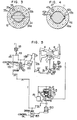
- Fig. 2 shows in detail the construction of the combined reheating valve incorporating therein the present invention.
- the combined reheating valve includes the RSV 6 of the upper level located on the upstream side with respect to the flow of steam, and an intercepting valve (hereinafter ICV) 7 of the lower level located on the downstream side thereof, the RSV 6 and the ICV 7 being mounted in a valve casing 25 having an upper cover 29 on its top and formed with a valve seat 26 shared by the RSV 6 and the ICV 7 as a valve seat.
- the RSV 6 on the upstream side will first be described.
- the RSV 6 comprises a planar plate portion 27 in the center and is in the form of an elongated cylinder in the up and down direction (or in the form of a letter H in cross section).
- the RSV 6 also has at its lowermost end surface a seat in contact with the valve seat 26, and is fitted at the outer peripheral surface of the cylinder for sliding movement to the inner peripheral surface of a guide cylinder 28 mounted in the upper cover 29 and formed with a plurality of steam apertures 36 at its uppermost end.
- This construction is intended to prevent the RSV 6 from wobbling when subjected to the force of steam.
- the planar plate 27 of the RSV 6 is formed in its central portion with a steam passageway 51, and a valve seat of a spherical daughter valve 12 is provided at the forward end of a valve stem 31 guided by a bush 30 inserted in the upper cover 29.
- the spherical daughter valve 12 serving as a bypass valve for the RSV 6 has applied thereto from above a cap 34 formed, as shown in Fig. 3, with grooves 33a and 33b for guiding opposite ends of a transversely inserted pin 32, and a bolt receiving opening 35a for inserting a clamping bolt 35 and steam inlet ducts 34a, the cap 34 being clamped to the body of the RSV 6 by the bolt 35.
- the valve stem 31 is formed with a spherical shoulder 31a in an upper portion of the daughter valve section at the forward end of the valve stem 31.
- the ICV 7 located on the downstream side will be described.
- the ICV 7 which is in the form of a parent valve (ICV) of an outer diameter smaller than the inner diameter of the cylinder of the RSV 6 located on the upstream side has an intercepting bypass valve (hereinafter ICBV) 11 which is a bypass valve screwed to the forward end portion of a valve stem 40 guided by a bush 39 inserted in a packing 38 attached to the lower portion of the valve casing 25 to better control the combined reheating valve.
- ICBV intercepting bypass valve
- the ICV 7 has bolted thereto as indicated at 47 a cap 46 formed, as shown in Fig. 4, with grooves 43a and 43b allowing lugs 42a and 42b of the ICBV 11 to slightly move vertically and with a shoulder 45 engaging a shoulder 44 of the ICBV 11 as well as a bolt receiving opening 47a and a steam passageway 46a, to have the ICBV 11 built-in the ICV 7.
- the ICV 7 is formed in its body with a steam passageway 37 allowing the reheating steam to flow therethrough.
- a steam strainer 48 of a cylindrical shape is mounted at the inner periphery of the valve casing 25 in a manner to surround the RSV 6 and ICV 7.
- reheating steam Q supplied from the reheater of the boiler flows into the valve casing 25 through a steam inlet 5a located substantially at the intermediate stage thereof and to the outer periphery of the RSV 6 in the closed condition and the outer peripheral portion of the guide cylinder 28 via the steam strainer 48. Thereafter the reheating steam flows into the upper half portion of the RSV 6 after passing through the steam apertures 36 in the guide cylinder 28.
- the reheating steam thus introduced into the upper half portion of the RSV 6 acts as a steam for closing the RSV 6 to provide an excellent seal to the valve seat 26 and the RSV 6 at the time the latter is fully closed.
- the RSV 6 is opened as follows.
- the valve stem 31 is first lifted by a hydraulic cylinder, not shown, for actuating the RSV 6, to lift the daughter valve 12 at the forward end of the valve stem 31 acting as a bypass valve until the spherical shoulder in the upper portion of the daughter valve portion is brought into contact with the shoulder of the cap 34. That is, this is the stroke S 1 of the daughter valve 12 and the RSV 6 is opened at the end of this stroke.
- the reheating steam disposed in the upper portion of the RSV 6 above the gap of the stroke S 1 flows through the steam passageway 51 into the lower chamber to raise the pressure therein, so that balance can be maintained.
- the ICV 7 and ICBV 11 are both in the fully closed position.
- the RSV 6 should be capable of being brought to a fully closed position instantaneously (in about 0.3 sec) in case of emergency of the turbine. Thus when the RSV moves a full stroke from the fully open position to the fully closed position, a sort of vacuum would occur in the guide cylinder 28 and interfere with the operation of closing the RSV 6. To avoid this accident, steam inlet apertures 36 are formed in the upper portion of the guide cylinder 28. By opening the RSV 6 as described hereinabove, the reheating steam flows into the head portion of the ICV 7 through a gap between the lowermost end portion of the RSV 6 and the valve seat 26.
- valve stem 40 coupled to a hydraulic cylinder, not shown, is brought into contact at its forward end with the ICBV 11 in a portion 11C and pushed upwardly so as to slightly open the ICBV 11 and allow the reheating steam to flow through the steam passageway 46a in the cap 46 and the steam passageway 37 in the ICV 7 into the lower chamber.
- the reheating steam thus introduced into the lower chamber of the ICV 7 flows into the chamber of the IP turbine 8 described by referring to Fig. 1, to start the steam turbine.
- the ICBV 11 has a relatively small diameter, so that it is possible to effect fine control commensurate with the rate of increase in the operation speed of the steam turbine.
- the reheating steam flows downwardly between the valve seat 26 and the ICV 7 into the IP turbine 8, so that the steam turbine can be operated in a normal fashion.
- the combined reheating steam valve according to the invention is constructed such that the RCV 6 and the ICV 7 can be fully opened and closed independently of each other without interfering with each other.
- the combined reheating valve according to the invention is constructed such that the reheating stop valve is located on the upstream side of the intercepting valve and the main valve of the intercepting valve has a bypass valve built therein.
- a combined reheating valve constructed such that the reheating stop valve is located on the upstream side of the intercepting valve and the reheating stop valve and the intercepting valve each have a bypass valve built therein.
- Fig. 5 shows a control mechanism for operating the combined reheating. valve according to the invention.
- a steam regulating valve 3 for controlling the reheating steam introduced from an evaporator, not shown, of the boiler into the HP turbine 4 has its opening and closing operation controlled by a servomotor 120 provided with a control valve 121 and having a lever 119 connected thereto.
- the lever 119 has connected thereto a speed relay 118 for operating the lever 119 in accordance with a control signal, not shown, and has connected to one end a link 132 whose operation is controlled by the speed relay 118.
- the link 132 has connected thereto a control valve 153 which controls the operation of a hydraulic cylinder 150 for operating the ICV 7 of the combined reheating valve 5.
- the ICBV 11 built-in the ICV 7 is connected through a valve stem to a piston of the hydraulic cylinder 150.
- the ICV 7 is intended to control reheating steam introduced into the IP turbine 8.
- actuation of the hydraulic cylinder 150 opens first the ICBV 11 and then the ICV 7.
- operation of the servomotor 120 is transmitted to the link 126 which successively actuates a rack 127, a pinion 128, a cam 129 and a roller 130, to thereby operate the steam regulating valve 3 through the lever 131 to control the volume of steam introduced into the HP turbine 4.
- the ICV 7 and the ICBV 11 are operated in conjunction with the steam regulating valve 3 by the speed relay 118.
- the RSV 6 In the valve casing 25 of the combined reheating valve 5, the RSV 6 is located in opposed relation to the ICV 7.
- the RSV 6 has built therein bypass valve 12, so that the valves 6 and 12 have their opening and closing operation controlled by an RSV hydraulic cylinder 151.
- Figs. 6a - 6c Operation for controlling the combined reheating valve of the aforesaid construction will be described by referring to Figs. 6a - 6c.
- Fig. 6a the valve is shown in a closed condition in which the RSV 6 is brought into contact with the valve seat of the valve casing 25 by the action of the RSV hydraulic cylinder 151 to close the steam passageway between a reheating steam inlet A and a reheating steam outlet B.
- the bypass valve 12 of the RSV 6 is in contact with the valve seat of the RSV 6 on the steam inlet side to thereby close the steam passageway.
- the ICV 7 is also in contact with the valve seat C of the valve casing 25 and the ICBV 11 is in contact with the valve seat of the ICV 7 on the steam inlet side.
- the turbine is under a small load. More specifically, the RSV 6 is located in an upper position after the turbine is started. In this case, the ICV 7 remains in contact with the valve seat C of the valve casing 25, to thereby avoid leaking of the steam. As the ICBV 11 is slightly moved upwardly by the ICV hydraulic cylinder 150, a steam inlet and a steam outlet of the ICV 7 are brought into communication with each other. Thus the reheating steam flows from the reheating steam inlet A in the direction of an arrow and is discharged through the reheating steam outlet B.' In this case, since the area of the opening of the steam passageway is small enough to effect control of the flow rate of the steam, the flow rate is controlled by the stroke of the ICBV 11.
- Fig. 6c shows the combined reheating valve 5 in a fully open condition. More specifically, the ICBV 11 is in contact with the valve seat of the ICV 7 on the steam inlet side and lifted, to thereby lift the ICV 7. Thus the ICV 7 is released from contact with the valve seat C of the valve casing 25, to thereby open the steam passageway. In this case, the reheating steam flows through the reheating steam inlet A and passes by the valve seat C of the valve casing 25 to the reheating steam outlet B as indicated by an arrow.
- the position between the positions shown in Figs. 6b and 6c is suitably selected by moving the ICBV 11 contacting the ICV 7.
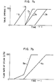
- Fig. 7 shows the steam turbine starting time t in relation to the valve opening V of the ICV and the steam regulating valve and the steam flow rate Q flowing downwardly through these valves.
- a straight line lla represents a valve opening of the ICBV 11 and a point llb indicate a fully open position of the ICBV 11.
- the ICV 7 is not opened until point llb is reached, and the flow rate of steam flowing into the IP turbine 8 is controlled by the ICBV 11 alone.
- the ICV 7 is opened as indicated by a straight line 7a to control the flow rate of the steam.
- Straight lines 3a and 3b represent the opening of the steam regulating valves (which are two in number in this embodiment) 3 for controlling the flow rate of the steam introduced into the HP turbine 4.
- a straight line 8a represents the flow rate of the steam flowing into the IP turbine 8 via the ICBV 11 or ICV 7 of the combined reheating valve.
- a straight lien 4a represents the flow rate of the steam flowing into the HP turbine 4 via the steam regulating valves 3.
- the steam regulating valves 3 and the ICBV 11 can be readily operated in conjunction with each other due to the feature that they are both connected to the speed relay 118. Also, by altering the linkage connected to the speed relay 118, it is possible to readily change the relation between the flow rate of the steam introduced into the HP turbine 4 and that introduced into the IP turbine 8.
- the flow rate of the steam can be controlled positively and with ease by opening and closing the ICV 7 by means of the ICBV 11.
Landscapes
- Engineering & Computer Science (AREA)
- General Engineering & Computer Science (AREA)
- Mechanical Engineering (AREA)
- Control Of Turbines (AREA)
Applications Claiming Priority (4)
| Application Number | Priority Date | Filing Date | Title |
|---|---|---|---|
| JP16909180A JPS5793609A (en) | 1980-12-02 | 1980-12-02 | Controller for combined reheating valve of turbine |
| JP169091/80 | 1980-12-02 | ||
| JP6336/81 | 1981-01-21 | ||
| JP633681A JPS6038521B2 (ja) | 1981-01-21 | 1981-01-21 | 組合せ蒸気弁 |
Publications (2)
| Publication Number | Publication Date |
|---|---|
| EP0053514A1 true EP0053514A1 (de) | 1982-06-09 |
| EP0053514B1 EP0053514B1 (de) | 1985-08-14 |
Family
ID=26340449
Family Applications (1)
| Application Number | Title | Priority Date | Filing Date |
|---|---|---|---|
| EP19810305661 Expired EP0053514B1 (de) | 1980-12-02 | 1981-12-01 | Kombiniertes Ventil |
Country Status (5)
| Country | Link |
|---|---|
| US (1) | US4481776A (de) |
| EP (1) | EP0053514B1 (de) |
| AU (1) | AU537607B2 (de) |
| CA (1) | CA1172134A (de) |
| DE (1) | DE3171849D1 (de) |
Cited By (3)
| Publication number | Priority date | Publication date | Assignee | Title |
|---|---|---|---|---|
| WO1998051952A1 (de) * | 1997-05-09 | 1998-11-19 | Siemens Aktiengesellschaft | Verfahren und vorrichtung zum erwärmen einer ventilanordnung |
| CN102434228A (zh) * | 2011-11-24 | 2012-05-02 | 哈尔滨汽轮机厂有限责任公司 | 一种抽汽汽轮机用的抽汽压力调整机构 |
| EP2642084A1 (de) * | 2012-03-22 | 2013-09-25 | Alstom Technology Ltd | Ventilanordnung für die Regelung der Dampfzufuhr zu einer geothermischen Dampfturbine |
Families Citing this family (39)
| Publication number | Priority date | Publication date | Assignee | Title |
|---|---|---|---|---|
| US5228597A (en) * | 1992-09-08 | 1993-07-20 | Wilshire Partners | Flow valve arrangement for beverage dispenser |
| CN1221471A (zh) * | 1996-04-26 | 1999-06-30 | 西门子公司 | 用于将过负荷蒸汽导入汽轮机中的控制装置和方法 |
| EP1191190A1 (de) * | 2000-09-20 | 2002-03-27 | Siemens Aktiengesellschaft | Verfahren zur Regelung einer Dampfturbine und Dampfturbine |
| US6638014B2 (en) | 2001-08-17 | 2003-10-28 | Alstom (Switzerland) Ltd | Valve arrangement for a power plant |
| US6655409B1 (en) * | 2002-09-04 | 2003-12-02 | General Electric Company | Combined stop and control valve for supplying steam |
| EP1557537B1 (de) * | 2002-10-29 | 2011-11-23 | Kabushiki Kaisha Toshiba | Dampfventil |
| US7543604B2 (en) * | 2006-09-11 | 2009-06-09 | Honeywell International Inc. | Control valve |
| JP4776494B2 (ja) * | 2006-10-18 | 2011-09-21 | 株式会社東芝 | 蒸気弁および蒸気タービン |
| JP5022853B2 (ja) * | 2007-10-03 | 2012-09-12 | 株式会社東芝 | 蒸気弁および発電設備 |
| JP5674521B2 (ja) * | 2011-03-25 | 2015-02-25 | 株式会社東芝 | 蒸気弁装置および蒸気タービンプラント |
| US9846440B2 (en) | 2011-12-15 | 2017-12-19 | Honeywell International Inc. | Valve controller configured to estimate fuel comsumption |
| US9851103B2 (en) | 2011-12-15 | 2017-12-26 | Honeywell International Inc. | Gas valve with overpressure diagnostics |
| US8905063B2 (en) | 2011-12-15 | 2014-12-09 | Honeywell International Inc. | Gas valve with fuel rate monitor |
| US8947242B2 (en) | 2011-12-15 | 2015-02-03 | Honeywell International Inc. | Gas valve with valve leakage test |
| US9074770B2 (en) | 2011-12-15 | 2015-07-07 | Honeywell International Inc. | Gas valve with electronic valve proving system |
| US8839815B2 (en) | 2011-12-15 | 2014-09-23 | Honeywell International Inc. | Gas valve with electronic cycle counter |
| US9835265B2 (en) | 2011-12-15 | 2017-12-05 | Honeywell International Inc. | Valve with actuator diagnostics |
| US8899264B2 (en) | 2011-12-15 | 2014-12-02 | Honeywell International Inc. | Gas valve with electronic proof of closure system |
| US9995486B2 (en) | 2011-12-15 | 2018-06-12 | Honeywell International Inc. | Gas valve with high/low gas pressure detection |
| US9557059B2 (en) | 2011-12-15 | 2017-01-31 | Honeywell International Inc | Gas valve with communication link |
| US9234661B2 (en) | 2012-09-15 | 2016-01-12 | Honeywell International Inc. | Burner control system |
| US10422531B2 (en) | 2012-09-15 | 2019-09-24 | Honeywell International Inc. | System and approach for controlling a combustion chamber |
| EP2868970B1 (de) | 2013-10-29 | 2020-04-22 | Honeywell Technologies Sarl | Regelungsvorrichtung |
| US10024439B2 (en) | 2013-12-16 | 2018-07-17 | Honeywell International Inc. | Valve over-travel mechanism |
| US9279345B2 (en) * | 2014-01-17 | 2016-03-08 | General Electric Company | Steam turbomachine valve having a valve member and seal assembly |
| US9841122B2 (en) | 2014-09-09 | 2017-12-12 | Honeywell International Inc. | Gas valve with electronic valve proving system |
| US9645584B2 (en) | 2014-09-17 | 2017-05-09 | Honeywell International Inc. | Gas valve with electronic health monitoring |
| US10605110B2 (en) * | 2015-10-14 | 2020-03-31 | Mechanical Dynamics & Analysis Llc | Bypass valve assembly for turbine generators |
| USD823992S1 (en) | 2015-10-27 | 2018-07-24 | Mechanical Dynamics & Analysis Llc | Poppet valve |
| US10503181B2 (en) | 2016-01-13 | 2019-12-10 | Honeywell International Inc. | Pressure regulator |
| US10564062B2 (en) | 2016-10-19 | 2020-02-18 | Honeywell International Inc. | Human-machine interface for gas valve |
| CN106523716B (zh) * | 2016-12-23 | 2020-04-17 | 上海电气电站设备有限公司 | 汽轮机一体式进汽阀 |
| JP6666280B2 (ja) * | 2017-02-15 | 2020-03-13 | 三菱日立パワーシステムズ株式会社 | 開閉弁、及び蒸気タービン |
| US11073281B2 (en) | 2017-12-29 | 2021-07-27 | Honeywell International Inc. | Closed-loop programming and control of a combustion appliance |
| US10697815B2 (en) | 2018-06-09 | 2020-06-30 | Honeywell International Inc. | System and methods for mitigating condensation in a sensor module |
| JP7236272B2 (ja) * | 2018-12-28 | 2023-03-09 | 三菱重工業株式会社 | 蒸気弁、及び発電システム |
| JP2022158044A (ja) * | 2021-04-01 | 2022-10-14 | 株式会社東芝 | 蒸気弁および蒸気タービン |
| CN114278396A (zh) * | 2021-12-03 | 2022-04-05 | 哈尔滨汽轮机厂有限责任公司 | 一种具备连续调节蒸汽流量功能的汽轮机用中压调节阀门 |
| JP2023087843A (ja) * | 2021-12-14 | 2023-06-26 | 株式会社東芝 | 蒸気弁および蒸気タービンプラント |
Citations (6)
| Publication number | Priority date | Publication date | Assignee | Title |
|---|---|---|---|---|
| US2561214A (en) * | 1950-07-26 | 1951-07-17 | Gen Electric | Combination balanced shutoff and throttling valve assembly |
| US3027137A (en) * | 1958-09-30 | 1962-03-27 | Gen Electric | Control mechanism for operating steam turbines under partial load with full arc admission |
| FR2215529A1 (de) * | 1973-01-25 | 1974-08-23 | Kalb Hans | |
| FR2309709A1 (fr) * | 1975-04-30 | 1976-11-26 | Bbc Brown Boveri & Cie | Soupape combinee a fermeture rapide et de regulation |
| FR2309708A1 (fr) * | 1975-04-30 | 1976-11-26 | Bbc Brown Boveri & Cie | Soupape combinee a fermeture rapide et de regulation |
| GB1470061A (en) * | 1973-04-02 | 1977-04-14 | Ishikawajima Harima Heavy Ind | Fluid control valve |
Family Cites Families (4)
| Publication number | Priority date | Publication date | Assignee | Title |
|---|---|---|---|---|
| US2333455A (en) * | 1942-04-04 | 1943-11-02 | Gen Electric | Valve arrangement |
| CH539805A (de) * | 1971-09-24 | 1973-07-31 | Bbc Brown Boveri & Cie | Kombiniertes Schnellschluss- und Regelventil |
| CH584350A5 (de) * | 1975-04-30 | 1977-01-31 | Bbc Brown Boveri & Cie | |
| DE3071051D1 (en) * | 1980-03-10 | 1985-10-10 | Bbc Brown Boveri & Cie | Excluding device for gaseous media comprising an equipment for damping of selfexciting acoustic vibrations in cavities |
-
1981
- 1981-11-27 AU AU77935/81A patent/AU537607B2/en not_active Expired
- 1981-11-30 US US06/325,869 patent/US4481776A/en not_active Expired - Lifetime
- 1981-11-30 CA CA000391212A patent/CA1172134A/en not_active Expired
- 1981-12-01 DE DE8181305661T patent/DE3171849D1/de not_active Expired
- 1981-12-01 EP EP19810305661 patent/EP0053514B1/de not_active Expired
Patent Citations (9)
| Publication number | Priority date | Publication date | Assignee | Title |
|---|---|---|---|---|
| US2561214A (en) * | 1950-07-26 | 1951-07-17 | Gen Electric | Combination balanced shutoff and throttling valve assembly |
| US3027137A (en) * | 1958-09-30 | 1962-03-27 | Gen Electric | Control mechanism for operating steam turbines under partial load with full arc admission |
| FR2215529A1 (de) * | 1973-01-25 | 1974-08-23 | Kalb Hans | |
| US3958600A (en) * | 1973-01-25 | 1976-05-25 | Hans Kalb | Combined starting and rapid shut-off mechanism for steam and gas turbines |
| GB1470061A (en) * | 1973-04-02 | 1977-04-14 | Ishikawajima Harima Heavy Ind | Fluid control valve |
| FR2309709A1 (fr) * | 1975-04-30 | 1976-11-26 | Bbc Brown Boveri & Cie | Soupape combinee a fermeture rapide et de regulation |
| FR2309708A1 (fr) * | 1975-04-30 | 1976-11-26 | Bbc Brown Boveri & Cie | Soupape combinee a fermeture rapide et de regulation |
| US4114651A (en) * | 1975-04-30 | 1978-09-19 | Bbc Brown Boveri & Company Limited | Combined stop and control valve |
| US4121617A (en) * | 1975-04-30 | 1978-10-24 | Bbc Brown, Boveri & Company Limited | Combined stop and control valve |
Cited By (4)
| Publication number | Priority date | Publication date | Assignee | Title |
|---|---|---|---|---|
| WO1998051952A1 (de) * | 1997-05-09 | 1998-11-19 | Siemens Aktiengesellschaft | Verfahren und vorrichtung zum erwärmen einer ventilanordnung |
| CN102434228A (zh) * | 2011-11-24 | 2012-05-02 | 哈尔滨汽轮机厂有限责任公司 | 一种抽汽汽轮机用的抽汽压力调整机构 |
| EP2642084A1 (de) * | 2012-03-22 | 2013-09-25 | Alstom Technology Ltd | Ventilanordnung für die Regelung der Dampfzufuhr zu einer geothermischen Dampfturbine |
| CN103321695A (zh) * | 2012-03-22 | 2013-09-25 | 阿尔斯通技术有限公司 | 地热发电 |
Also Published As
| Publication number | Publication date |
|---|---|
| AU7793581A (en) | 1982-07-15 |
| AU537607B2 (en) | 1984-07-05 |
| CA1172134A (en) | 1984-08-07 |
| US4481776A (en) | 1984-11-13 |
| DE3171849D1 (en) | 1985-09-19 |
| EP0053514B1 (de) | 1985-08-14 |
Similar Documents
| Publication | Publication Date | Title |
|---|---|---|
| EP0053514B1 (de) | Kombiniertes Ventil | |
| US3971412A (en) | Quick acting valves | |
| GB1418177A (en) | Servopiston-operated valves | |
| GB1503243A (en) | Safety trip valve for gas or steam turbines | |
| US4041980A (en) | Control valve having two independently driven valves | |
| JPS6038521B2 (ja) | 組合せ蒸気弁 | |
| CA1210664A (en) | Valve assemblies | |
| CN88102794A (zh) | 可调阀座力的阀系统 | |
| EP0073148B1 (de) | Hydraulisches Steuersystem | |
| CN210599129U (zh) | 一种小流量汽轮机的中间抽汽调节机构 | |
| JPS6139498B2 (de) | ||
| JPS62141395A (ja) | スチ−ムトラツプ | |
| US3456990A (en) | Air pressure operated braking systems | |
| US3790076A (en) | Pilot-operated steam traps | |
| EP0419946B1 (de) | Stellantrieb | |
| US3820917A (en) | Safety device for preventing the excessive speed of water turbines | |
| JPS6033446Y2 (ja) | 圧力制御弁装置用パイロツト圧調整弁 | |
| JPS6157442B2 (de) | ||
| US2586688A (en) | Automatically and manually controlled servomotor for interceptor valve of turbine and reheater apparatus | |
| US3403891A (en) | Full arc/partial arc admission using control valves | |
| CN210153222U (zh) | 一种可抵消不平衡力的双座控制阀 | |
| KR0179581B1 (ko) | 중장비의 유압작동기 제어용 변위비례감압밸브 | |
| JPS6128543Y2 (de) | ||
| DE111487C (de) | ||
| CA1138299A (en) | Gas valve assembly |
Legal Events
| Date | Code | Title | Description |
|---|---|---|---|
| PUAI | Public reference made under article 153(3) epc to a published international application that has entered the european phase |
Free format text: ORIGINAL CODE: 0009012 |
|
| AK | Designated contracting states |
Designated state(s): DE FR |
|
| 17P | Request for examination filed |
Effective date: 19821206 |
|
| GRAA | (expected) grant |
Free format text: ORIGINAL CODE: 0009210 |
|
| AK | Designated contracting states |
Designated state(s): DE FR |
|
| REF | Corresponds to: |
Ref document number: 3171849 Country of ref document: DE Date of ref document: 19850919 |
|
| ET | Fr: translation filed | ||
| PLBE | No opposition filed within time limit |
Free format text: ORIGINAL CODE: 0009261 |
|
| STAA | Information on the status of an ep patent application or granted ep patent |
Free format text: STATUS: NO OPPOSITION FILED WITHIN TIME LIMIT |
|
| 26N | No opposition filed | ||
| PGFP | Annual fee paid to national office [announced via postgrant information from national office to epo] |
Ref country code: FR Payment date: 19930914 Year of fee payment: 13 |
|
| PGFP | Annual fee paid to national office [announced via postgrant information from national office to epo] |
Ref country code: DE Payment date: 19931231 Year of fee payment: 13 |
|
| PG25 | Lapsed in a contracting state [announced via postgrant information from national office to epo] |
Ref country code: FR Effective date: 19950831 |
|
| PG25 | Lapsed in a contracting state [announced via postgrant information from national office to epo] |
Ref country code: DE Effective date: 19950901 |
|
| REG | Reference to a national code |
Ref country code: FR Ref legal event code: ST |