EP0053083A1 - Direct current contact device - Google Patents
Direct current contact device Download PDFInfo
- Publication number
- EP0053083A1 EP0053083A1 EP81420152A EP81420152A EP0053083A1 EP 0053083 A1 EP0053083 A1 EP 0053083A1 EP 81420152 A EP81420152 A EP 81420152A EP 81420152 A EP81420152 A EP 81420152A EP 0053083 A1 EP0053083 A1 EP 0053083A1
- Authority
- EP
- European Patent Office
- Prior art keywords
- blade
- source
- blades
- contactor according
- electrical
- Prior art date
- Legal status (The legal status is an assumption and is not a legal conclusion. Google has not performed a legal analysis and makes no representation as to the accuracy of the status listed.)
- Granted
Links
Images


Classifications
-
- F—MECHANICAL ENGINEERING; LIGHTING; HEATING; WEAPONS; BLASTING
- F21—LIGHTING
- F21L—LIGHTING DEVICES OR SYSTEMS THEREOF, BEING PORTABLE OR SPECIALLY ADAPTED FOR TRANSPORTATION
- F21L4/00—Electric lighting devices with self-contained electric batteries or cells
- F21L4/005—Electric lighting devices with self-contained electric batteries or cells the device being a pocket lamp
-
- F—MECHANICAL ENGINEERING; LIGHTING; HEATING; WEAPONS; BLASTING
- F21—LIGHTING
- F21V—FUNCTIONAL FEATURES OR DETAILS OF LIGHTING DEVICES OR SYSTEMS THEREOF; STRUCTURAL COMBINATIONS OF LIGHTING DEVICES WITH OTHER ARTICLES, NOT OTHERWISE PROVIDED FOR
- F21V23/00—Arrangement of electric circuit elements in or on lighting devices
- F21V23/04—Arrangement of electric circuit elements in or on lighting devices the elements being switches
- F21V23/0414—Arrangement of electric circuit elements in or on lighting devices the elements being switches specially adapted to be used with portable lighting devices
-
- H—ELECTRICITY
- H01—ELECTRIC ELEMENTS
- H01M—PROCESSES OR MEANS, e.g. BATTERIES, FOR THE DIRECT CONVERSION OF CHEMICAL ENERGY INTO ELECTRICAL ENERGY
- H01M50/00—Constructional details or processes of manufacture of the non-active parts of electrochemical cells other than fuel cells, e.g. hybrid cells
- H01M50/20—Mountings; Secondary casings or frames; Racks, modules or packs; Suspension devices; Shock absorbers; Transport or carrying devices; Holders
- H01M50/204—Racks, modules or packs for multiple batteries or multiple cells
- H01M50/207—Racks, modules or packs for multiple batteries or multiple cells characterised by their shape
- H01M50/213—Racks, modules or packs for multiple batteries or multiple cells characterised by their shape adapted for cells having curved cross-section, e.g. round or elliptic
-
- H—ELECTRICITY
- H01—ELECTRIC ELEMENTS
- H01M—PROCESSES OR MEANS, e.g. BATTERIES, FOR THE DIRECT CONVERSION OF CHEMICAL ENERGY INTO ELECTRICAL ENERGY
- H01M50/00—Constructional details or processes of manufacture of the non-active parts of electrochemical cells other than fuel cells, e.g. hybrid cells
- H01M50/50—Current conducting connections for cells or batteries
-
- Y—GENERAL TAGGING OF NEW TECHNOLOGICAL DEVELOPMENTS; GENERAL TAGGING OF CROSS-SECTIONAL TECHNOLOGIES SPANNING OVER SEVERAL SECTIONS OF THE IPC; TECHNICAL SUBJECTS COVERED BY FORMER USPC CROSS-REFERENCE ART COLLECTIONS [XRACs] AND DIGESTS
- Y02—TECHNOLOGIES OR APPLICATIONS FOR MITIGATION OR ADAPTATION AGAINST CLIMATE CHANGE
- Y02E—REDUCTION OF GREENHOUSE GAS [GHG] EMISSIONS, RELATED TO ENERGY GENERATION, TRANSMISSION OR DISTRIBUTION
- Y02E60/00—Enabling technologies; Technologies with a potential or indirect contribution to GHG emissions mitigation
- Y02E60/10—Energy storage using batteries
Definitions
- the invention relates to a new type of electrical contactor operating on a battery or the like.
- an "electrical contactor” is a switch used to establish connections between different circuits or electrical devices.
- this contactor is used to establish the electrical connection, therefore the passage of current, between the electrical source of direct current (battery, accumulator, battery or the like) and the member using this current (bulb, motor, etc. .).
- the invention aims to produce this type of product.
- plastic all known materials can be used insofar as under the conditions of use, they are not brittle and are capable of forming blades capable of receiving a certain flexion and finally, they are capable of being covered with an electrically conductive coating.
- use is made of ABS or styrene resins.
- the part is one piece.
- plastics such as injection.
- a conductive coating it is possible to use either known coatings or paints. In practice, copper plating is carried out by electroplating. In addition, as said, the allowable elastic coefficient of elongation of the flexible strip and of the bond-flexion strip are as close as possible to that of the conductive coating. In fact, the flexion of these two blades is calculated to adapt them to the lowest elongation.
- the dimensions of the part are calculated according to the application envisaged.
- small batteries or micro-accumulators can also be used, as the case may be.
- blades (1) and (2) are connected to their base by a bending blade (4) in the shape of a rounded V (5), this rounded being intended to receive the pole (6) of the stack (3).
- this receptacle (8) is cylindrical and has inside the spiral grooves (11), directly molded, intended to allow the face of the base of this light bulb.
- this member is an electric motor (FIG. 3)
- this receptacle can have a flared shape (12) intended to receive the metal cage output from this motor.
- the blade (2) called flexible has at its end a pusher formed in two parts (13) and (14) in the form of a button which has come directly into molding.
- the bent part (15) allows the blade (2) to flex by a simple manual or controlled pressure (fugitive contact or continuous contact) on the button (13), the counter-button ( 1 4) then coming into contact with the receptacle (8) and thus establishes the electrical connection between the user member (bulb, motor) connected to the receptacle (8) and with the blade ( 1 0) (see 6) and between the other pole of the pile (3), thanks to the conductive coating with which the monobloc part is covered.
- these blades have on their length legs (16), (17), (18 ), molded, offset from each other and forming clips.
- suitable elements can be provided on these blades, such as holes or bosses.
- this contactor can be used successfully in uses where it is essential to establish an electrical connection between a direct current source and a user member, such as for example a toy or a portable lighting system.
Abstract
Description
L'invention concerne un.nouveau type de contacteur électrique fonctionnant sur pile ou similaire.The invention relates to a new type of electrical contactor operating on a battery or the like.
Comme on le sait, un "contacteur électrique" est un interrupteur servant à établir des liaisons entre différents circuits ou appareils électriques. Dans le cas présent, ce contacteur sert à établir la liaison électrique, donc le passage du courant, entre la source électrique du courant continu (pile, accumulateur, batterie ou similaire) et l'organe utilisateur de ce courant (ampoule, moteur, etc.).As is known, an "electrical contactor" is a switch used to establish connections between different circuits or electrical devices. In this case, this contactor is used to establish the electrical connection, therefore the passage of current, between the electrical source of direct current (battery, accumulator, battery or the like) and the member using this current (bulb, motor, etc. .).
A ce jour, le plus généralement, on a essentiellement proposé deux formules pour réaliser ces liaisons.To date, most generally, two formulas have essentially been proposed for making these connections.
Tout d'abord, on a proposé d'utiliser des fils électriques. Si ce mode de liaison souple présente de nombreux avantages, il a pour lui l'inconvénient notable d'être coûteux à réaliser.First, it has been proposed to use electrical wires. If this flexible connection mode has many advantages, it has the significant disadvantage of being costly to produce.
En pratique, les contacteurs les plus répandus sont à ce jour à base de lames métalliques souples, dénommées souvent lames de contact. Bien que très largement répandue dans tous les appareils où l'on utilise des piles, tels-que les jouets ou les dispositifs d'éclairage portatifs (lampes de poche, etc), cette solution présente des inconvénients notables. On peut citer :
- - du fait du manque d'élasticité des lames, une fiabilité douteuse dans le temps,
- - la réalisation de forme limitée,
- - la nécessité d'utiliser plusieurs lames, de formes appropriées, pour réaliser un contact, ainsi que la pré= sence obligatoire d'un interrupteur et d'éléments d'accrochage isolants,
- - la difficulté à absorber les tolérances dimensionnelles des piles,
- - la mauvaise résistance aux chocs répétés, ce qui limite leur emploi dans l'industrie du jouet où l'on exige une certaine résistance aux chutes répétées, alors que cette industrie a un fort besoin de ce type de produit,
- - enfin, un prix élevé, notamment par suite des techniques assez peu précises utilisées pour courber les lames, et des manoeuvres de montage.
- - due to the lack of elasticity of the blades, doubtful reliability over time,
- - the realization of limited form,
- - the need to use several blades, of appropriate shapes, to make a contact, as well as the compulsory presence of a switch and insulating hooking elements,
- - difficulty absorbing the dimensional tolerances of the cells,
- - poor resistance to repeated shocks, which limits their use in the toy industry where some resistance to repeated drops is required, while this industry has a great need for this type of product,
- - Finally, a high price, particularly due to the rather imprecise techniques used to bend the blades, and assembly maneuvers.
Le marché demande de plus en plus des contacteurs pour pile électrique ou similaire plus fiables, plus résistants, moins coûteux et même plus miniaturisables. L'invention vise à réaliser ce type de produit.The market increasingly demands more reliable, more resistant, less expensive and even more miniaturizable contactors for electric cells or the like. The invention aims to produce this type of product.
Elle se rapporte à un nouveau contacteur électrique destiné à assurer la liaison électrique entre une source de courant continu (pile, batterie, accumulateur) et un organe utilisateur de c-e courant (moteur, ampoule...). Ce contacteur se caractérise en ce qu'il est formé par une pièce monobloc en matière plastique semi-rigide, isolante, recouverte d'un revêtement conducteur, ladite pièce étant constituée par :
- - deux lames parallèles, disposées de part et d'autre de la source du courant continu, et équipées de moyens pour maintenir cette source en place, lesdites lames étant réunies entre elles à leur base par une lame de liaison-flexion destinée, d'une part, à assurer le contact avec l'un des pôles de la source électrique et, d'autre part, à absorber à la fois les variations dimensionnelles de cette source électrique et l'énergie de choc lors des chutes,
- - une des deux lames est fixe et comporte à son extrémité un moyen apte à assurer la liaison entre l'autre pôle de la source électrique et l'organe utilisateur et présente sur sa longueur une solution de continuité dans la transmission du courant,
- - l'autre lame, souple, présente à son extrémité un moyen pour assurer la liaison électrique avec l'organe utilisateur et joue le rôle de lame de flexion pour ledit moyen.
- - two parallel blades, arranged on either side of the source of direct current, and equipped with means for holding this source in place, said blades being joined together at their base by a connecting-bending blade intended for on the one hand, to ensure contact with one of the poles of the electrical source and, on the other hand, to absorb both the dimensional variations of this electrical source and the impact energy during falls,
- one of the two blades is fixed and comprises at its end a means capable of ensuring the connection between the other pole of the electrical source and the user member and has along its length a solution of continuity in the transmission of current,
- - The other flexible blade has at its end a means for ensuring the electrical connection with the user member and acts as a bending blade for said means.
Avantageusement :
- - les moyens pour maintenir la source électrique en place entre les deux lames sont constitués par des clips ou des pattes moulées directement sur chacune des faces en regard des lames ;
- - la lame de liaison-flexion a une forme générale de V renversé, arrondi à la pointe, relié par ses branches à la base des deux lames parallèles, la pointe arrondie du V venant assurer le contact avec le pôle concerné de la source électrique ;
- - le moyen pour assurer la liaison entre l'autre pô- le de la source électrique et l'organe utilisateur placé à l'extrémité des lames fixes est formé par un réceptacle connecté à l'extrémité d'une lame et dans lequel vient se placer l'organe utilisateur ;
- - dans le cas d'une ampoule d'éclairage, ce réceptacle, venu directement de moulage, forme douille pour le culot de cette ampoule ;
- - dans le cas d'un moteur électrique, ce réceptacle reçoit la cage métallique de sortie du moteur ;
- - la solution de continuité dans la transmission du courant portée par cette lame fixe est réalisée, soit par une couche de vernis, soit par une forme moulée ou usinée particulière, découpée dans cette lame fixe et qui ultérieurement empêchera le dépôt de la couche conductrice (par exemple une gorge étroite plus profonde que large) ;
- - le moyen pour assurer la liaison entre l'extrémité de la lame souple et l'organe utilisateur est un poussoir moulé directement à l'extrémité de cette lame souple ; ce poussoir peut être à contact fugitif ou continu avec accrochage ;
- - le coefficient d'allongement élastique admissible de cette lame souple.et celui de la lame de flexion-liaison sont le plus près possible de celui du revêtement conducteur.
- the means for holding the electric source in place between the two blades are constituted by clips or tabs molded directly on each of the faces facing the blades;
- - The connecting-bending blade has a general shape of an inverted V, rounded at the tip, connected by its branches to the base of the two parallel blades, the rounded tip of the V coming into contact with the pole concerned from the electrical source;
- the means for ensuring the connection between the other pole of the electrical source and the user member placed at the end of the fixed blades is formed by a receptacle connected to the end of a blade and in which comes place the user device;
- - In the case of a light bulb, this receptacle, coming directly from molding, forms a socket for the base of this bulb;
- - In the case of an electric motor, this receptacle receives the metal cage for the output of the motor;
- - the continuity solution in the transmission of the current carried by this fixed strip is produced, either by a layer of varnish, or by a particular molded or machined shape, cut from this fixed strip and which subsequently will prevent the deposition of the conductive layer ( for example a narrow throat deeper than wide);
- - The means for ensuring the connection between the end of the flexible blade and the user member is a pusher molded directly at the end of this flexible blade; this pusher can be in fugitive or continuous contact with hanging;
- - the allowable elastic coefficient of elongation of this flexible strip. and that of the bending-bonding strip are as close as possible to that of the conductive coating.
Comme matière plastique, on peut faire appel à toutes les matières connues dans la mesure où dans les conditions d'utilisation, elles ne soient pas cassantes et soient aptes à former des lames susceptibles de recevoir une certaine flexion et enfin, elles soient aptes à être recouvertes d'un revêtement conducteur de l'électricité. En pratique, on fait appel à des résines d'ABS ou styré- niques.As plastic, all known materials can be used insofar as under the conditions of use, they are not brittle and are capable of forming blades capable of receiving a certain flexion and finally, they are capable of being covered with an electrically conductive coating. In practice, use is made of ABS or styrene resins.
Comme déjà dit, il est indispensable que la pièce soit monobloc. Ainsi, on la réalise par des techniques connues de travail des matières plastiques, telles que l'injection.As already said, it is essential that the part is one piece. Thus, it is carried out by known techniques for working with plastics, such as injection.
Comme revêtement conducteur, on peut faire appel soit à des revêtements connus, soit à des peintures. En pratique, on effectue un cuivrage par galvanoplastie. En outre, comme dit, le coefficient d'allongement élastique admissible de la lame souple et de la lame de liaison-flexion sont le plus près possible de celui du revêtement conducteur. En fait, on calcule la flexion de ces deux lames pour les adapter au plus faible allongement.As a conductive coating, it is possible to use either known coatings or paints. In practice, copper plating is carried out by electroplating. In addition, as said, the allowable elastic coefficient of elongation of the flexible strip and of the bond-flexion strip are as close as possible to that of the conductive coating. In fact, the flexion of these two blades is calculated to adapt them to the lowest elongation.
Les dimensions de la pièce (largeur, épaisseur;, longueur des lames, etc...) sont calculées en fonction de l'application envisagée.The dimensions of the part (width, thickness; length of the blades, etc.) are calculated according to the application envisaged.
Comme source de courant électrique, si le plus généralement on fait appel à des piles cylindriques, on peut également selon les cas utiliser des petites batteries ou des micro-accumulateurs.As a source of electric current, if more generally cylindrical batteries are used, small batteries or micro-accumulators can also be used, as the case may be.
La manière dont l'invention peut être réalisée et les avantages qui en découlent ressortiront mieux des exemples de réalisation qui suivent donnés à titre indicatif mais non limitatif.The manner in which the invention can be implemented and the advantages which ensue therefrom will emerge more clearly from the following exemplary embodiments given by way of indication but not limitation.
- La figure 1 est une représentation en perspective sommaire d'un contacteur électrique conforme à l'invention.Figure 1 is a summary perspective representation of an electrical contactor according to the invention.
- La figure 2 est une coupe longitudinale de ce contacteur selon la figure 1.FIG. 2 is a longitudinal section of this contactor according to FIG. 1.
- La figure 3 montre une autre forme de réalisation de ce contacteur.Figure 3 shows another embodiment of this contactor.
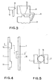
- La figure 4 est une vue détaillée de dessus des deux lames enserrant la pile alors que la figure 5 est une vue en coupe de la figure 4 selon l'axe 1-1'.Figure 4 is a detailed top view of the two blades enclosing the stack while Figure 5 is a sectional view of Figure 4 along the axis 1-1 '.
Ce contacteur électrique (voir figures 1 et 2) se compose d'une pièce monobloc en résine ABS revêtue par galvanoplastie d'une couche de cuivre sur toute sa surface, à l'exception de la portion (7) non conductrice définie ci-après. Cette pièce est formée de deux lames parallèles, respectivement :
- une lame dite fixe (1),
- - une lame dite souple (2), du moins à son extrémité libre, dont l'écartement entre elles est légèrement supérieur au diamètre de la pile (3) formant source électrique.
- a so-called fixed blade (1),
- - A so-called flexible blade (2), at least at its free end, the spacing between them is slightly greater than the diameter of the battery (3) forming an electrical source.
Ces lames (1) et (2) sont reliées.à leur base par une lame de flexion (4) en forme de V arrondi (5), cet arrondi étant destiné à recevoir le pôle (6) de la pile (3).These blades (1) and (2) are connected to their base by a bending blade (4) in the shape of a rounded V (5), this rounded being intended to receive the pole (6) of the stack (3).
La lame (1) dite fixe présente :
- - une portion (7) non conductrice ; pour ce fadre, avant le traitement de galvanoplastie, on a recouvert cette portion (7) d'un vernis approprié,
- - et à son extrémité un réceptacle (8) destiné à assurer la liaison électrique entre le pôle (10) de la; pile (3) et l'organe utilisateur ; la jonction entre la lame (1) proprement dite et ce réceptacle (8) se fait grâce à une portion coudée (9) destinée à absorber les variations dimensionnelles.
- - a non-conductive portion (7); for this fadre, before the electroplating treatment, this portion (7) was covered with an appropriate varnish,
- - And at its end a receptacle (8) intended to ensure the electrical connection between the pole (10) of the; battery (3) and the user device; the junction between the blade (1) proper and this receptacle (8) is made thanks to a bent portion (9) intended to absorb dimensional variations.
Dans le cas où cet organe utilisateur est une ampoule électrique (figures 1 et 2), ce réceptacle (8) est cylindrique et présente à l'intérieur des rainures (11) spiralées, venues directement de moulage, destinées à permettre le visage du culot de cette ampoule. En revanche, si cet organe est un moteur électrique (figure 3), ce réceptacle peut avoir une forme évasée (12) destinée à recevoir la cage métallique de sortie de ce moteur.In the case where this user member is a light bulb (Figures 1 and 2), this receptacle (8) is cylindrical and has inside the spiral grooves (11), directly molded, intended to allow the face of the base of this light bulb. On the other hand, if this member is an electric motor (FIG. 3), this receptacle can have a flared shape (12) intended to receive the metal cage output from this motor.
La lame (2) dite souple présente à son extrémité un poussoir formé en deux parties (13) et (14) en forme de bouton venues directement en moulage. La partie coudée (15) permet la flexion de la lame (2) par une simple pression manuelle ou contrôlée (contact fugitif ou contact continu) sur le bouton (13), le contre-bouton (14) venant alors au contact du réceptacle (8) et établit ainsi la liaison électrique entre l'organe utilisateur (ampoule, moteur) connecté au réceptacle (8) et au pale (10) (voir 6) et entre l'autre pôle de la pile (3), grâce au revêtement conducteur dont est recouvert la pièce monobloc.The blade (2) called flexible has at its end a pusher formed in two parts (13) and (14) in the form of a button which has come directly into molding. The bent part (15) allows the blade (2) to flex by a simple manual or controlled pressure (fugitive contact or continuous contact) on the button (13), the counter-button ( 1 4) then coming into contact with the receptacle (8) and thus establishes the electrical connection between the user member (bulb, motor) connected to the receptacle (8) and with the blade ( 1 0) (see 6) and between the other pole of the pile (3), thanks to the conductive coating with which the monobloc part is covered.
Comme la portion (7) forme une solution de continuité, le courant ne circule donc que dans la lame souple (2).As the portion (7) forms a solution of continuity, the current therefore only flows in the flexible blade (2).
Afin d'assurer le maintien de la pile (3) entre les deux lames parallèles (1) et (2) (voir figures 4 et 5), ces lames présentent sur leur longueur des pattes (16), (17), (18), venues de moulage, décalées les unes par rapport aux autres et formant clips. De même, pour obliger l'utilisateur à mettre la pile d'un côté préférentiel, on peut ménager sur ces lames des éléments appropriés, tels que des trous ou des bossages.To maintain the stack (3) between the two parallel blades (1) and (2) (see Figures 4 and 5), these blades have on their length legs (16), (17), (18 ), molded, offset from each other and forming clips. Likewise, to force the user to put the battery on a preferential side, suitable elements can be provided on these blades, such as holes or bosses.
Ce nouveau type de contacteur présente de nombreux avantages par rapport aux réalisations actuelles. On peut citer :
- - du fait qu'il soit monobloc, la facilité de construction et de montage,
- - un prix de revient nettement amélioré que l'on estime de moitié par rapport aux solutions actuelles à lames métalliques,
- - la facilité de stockage et de manipulation,
- - la fiabilité accrue due à la précision de l'ensemble,
- - la bonne résistance aux chutes répétées,
- - la possibilité d'absorber facilement les tolérances dimensionnelles des piles.
- - the fact that it is in one piece, the ease of construction and assembly,
- - a significantly improved cost price which is estimated to be half compared to current solutions with metal blades,
- - ease of storage and handling,
- - increased reliability due to the precision of the assembly,
- - good resistance to repeated falls,
- - the possibility of easily absorbing the dimensional tolerances of the cells.
De la sorte, on peut utiliser ce contacteur avec succès dans les utilisations où il est indispensable d'établir une liaison électrique entre une source de courant continu et un organe utilisateur, tel que par exemple un jouet ou un système d'éclairage portatif.In this way, this contactor can be used successfully in uses where it is essential to establish an electrical connection between a direct current source and a user member, such as for example a toy or a portable lighting system.
Claims (10)
Priority Applications (1)
| Application Number | Priority Date | Filing Date | Title |
|---|---|---|---|
| AT81420152T ATE5436T1 (en) | 1980-11-21 | 1981-10-15 | DC CONTACT. |
Applications Claiming Priority (2)
| Application Number | Priority Date | Filing Date | Title |
|---|---|---|---|
| FR8025023A FR2494892A1 (en) | 1980-11-21 | 1980-11-21 | ELECTRIC CONTACTOR WITH CONTINUOUS CURRENT |
| FR8025023 | 1980-11-21 |
Publications (2)
| Publication Number | Publication Date |
|---|---|
| EP0053083A1 true EP0053083A1 (en) | 1982-06-02 |
| EP0053083B1 EP0053083B1 (en) | 1983-11-23 |
Family
ID=9248340
Family Applications (1)
| Application Number | Title | Priority Date | Filing Date |
|---|---|---|---|
| EP81420152A Expired EP0053083B1 (en) | 1980-11-21 | 1981-10-15 | Direct current contact device |
Country Status (7)
| Country | Link |
|---|---|
| US (1) | US4393284A (en) |
| EP (1) | EP0053083B1 (en) |
| JP (1) | JPS5792338U (en) |
| AT (1) | ATE5436T1 (en) |
| DE (1) | DE3161511D1 (en) |
| ES (1) | ES261595Y (en) |
| FR (1) | FR2494892A1 (en) |
Families Citing this family (1)
| Publication number | Priority date | Publication date | Assignee | Title |
|---|---|---|---|---|
| US5795211A (en) * | 1996-01-11 | 1998-08-18 | Satellite Balloon Manufacturer Of Hong Kong Ltd. | Illuminated non-latex balloon |
Citations (2)
| Publication number | Priority date | Publication date | Assignee | Title |
|---|---|---|---|---|
| US2714152A (en) * | 1951-08-13 | 1955-07-26 | Brown & Bigelow | Key chain pocket flashlight |
| US3737648A (en) * | 1971-11-11 | 1973-06-05 | C Franc | Packaging and mounting holders for illuminated gift packages, greeting cards and the like |
Family Cites Families (5)
| Publication number | Priority date | Publication date | Assignee | Title |
|---|---|---|---|---|
| US2542613A (en) * | 1947-09-08 | 1951-02-20 | E A Lab Inc | Dry cell lamp switch |
| US2522660A (en) * | 1947-09-29 | 1950-09-19 | Badger Carton Co | Foldable holder for flashlight elements |
| US3105233A (en) * | 1962-08-17 | 1963-09-24 | A L Construction & Sales Corp | Fish callers |
| US3720825A (en) * | 1972-02-29 | 1973-03-13 | C Franc | Mounting apparatus for illuminated gift packages, greeting cards, or the like |
| US4314317A (en) * | 1980-01-23 | 1982-02-02 | Robson Jerry A | Flashlight |
-
1980
- 1980-11-21 FR FR8025023A patent/FR2494892A1/en active Granted
-
1981
- 1981-10-15 EP EP81420152A patent/EP0053083B1/en not_active Expired
- 1981-10-15 DE DE8181420152T patent/DE3161511D1/en not_active Expired
- 1981-10-15 AT AT81420152T patent/ATE5436T1/en not_active IP Right Cessation
- 1981-11-17 JP JP1981171333U patent/JPS5792338U/ja active Pending
- 1981-11-19 US US06/322,755 patent/US4393284A/en not_active Expired - Fee Related
- 1981-11-20 ES ES1981261595U patent/ES261595Y/en not_active Expired
Patent Citations (2)
| Publication number | Priority date | Publication date | Assignee | Title |
|---|---|---|---|---|
| US2714152A (en) * | 1951-08-13 | 1955-07-26 | Brown & Bigelow | Key chain pocket flashlight |
| US3737648A (en) * | 1971-11-11 | 1973-06-05 | C Franc | Packaging and mounting holders for illuminated gift packages, greeting cards and the like |
Also Published As
| Publication number | Publication date |
|---|---|
| FR2494892A1 (en) | 1982-05-28 |
| ES261595U (en) | 1982-10-16 |
| JPS5792338U (en) | 1982-06-07 |
| ATE5436T1 (en) | 1983-12-15 |
| EP0053083B1 (en) | 1983-11-23 |
| US4393284A (en) | 1983-07-12 |
| ES261595Y (en) | 1983-04-01 |
| FR2494892B1 (en) | 1982-12-03 |
| DE3161511D1 (en) | 1983-12-29 |
Similar Documents
| Publication | Publication Date | Title |
|---|---|---|
| EP0810688A1 (en) | Electrical connector for connecting electrical conductors | |
| FR2538954A1 (en) | RECHARGEABLE BATTERY WITH ANNULAR CHARGING TERMINAL | |
| FR2638031A1 (en) | ADAPTER FOR CONNECTION TO AN EXTERNAL POWER SUPPLY | |
| FR2524119A1 (en) | MINIATURE FLASHLIGHT | |
| CA2152514A1 (en) | Mobile component of an electrical connection with connecting cable and grip handle | |
| CA1083643A (en) | Switch for flash light | |
| EP1867009A1 (en) | Clamping device for a connection terminal | |
| EP0469938B1 (en) | Brush holder for electric commutator machine | |
| EP0053083B1 (en) | Direct current contact device | |
| FR2642230A1 (en) | ELECTRICAL CONNECTOR | |
| WO1987002196A1 (en) | Improvements to electric contact sockets | |
| FR2550002A1 (en) | CONTACT GROUP FOR ELECTRICAL EQUIPMENT | |
| EP0080389A1 (en) | Electrical contact and application to a connector | |
| FR3029698A1 (en) | ELECTRICAL CONNECTION ELEMENT WITH INSULATING SHEATHING OF AN ELECTRIC WIRE | |
| EP0135409B1 (en) | Security device for an electrical apparatus with a rechargeable battery | |
| EP0004503B1 (en) | Casing for electric pocket torches | |
| EP1100105A1 (en) | Wiring method for cicuit breaker | |
| FR2936656A1 (en) | Electric connection terminal e.g. phase terminal, for e.g. plug-in connector, has clamping spring with end branch that has anchoring portion inclined so as to orient sharp anchoring edge along direction opposite to introduction direction | |
| FR2904482A1 (en) | CONNECTOR FOR BATTERY TERMINAL | |
| FR2996283A1 (en) | LUMINAIRE WITH LENS HEAD | |
| FR2578103A1 (en) | Battery box, in particular for military use | |
| CH660257A5 (en) | FUSE HOLDER. | |
| FR2858718A1 (en) | TERMINAL CONNECTOR | |
| EP1134846B1 (en) | Electrical connector | |
| FR2805660A1 (en) | Car starter motor contact assembly having contact unit cap cover and upper outer sections with a metallic strip cap non parallel to the cap |
Legal Events
| Date | Code | Title | Description |
|---|---|---|---|
| PUAI | Public reference made under article 153(3) epc to a published international application that has entered the european phase |
Free format text: ORIGINAL CODE: 0009012 |
|
| AK | Designated contracting states |
Designated state(s): AT BE CH DE GB IT LU NL SE |
|
| 17P | Request for examination filed |
Effective date: 19820622 |
|
| ITF | It: translation for a ep patent filed |
Owner name: JACOBACCI & PERANI S.P.A. |
|
| GRAA | (expected) grant |
Free format text: ORIGINAL CODE: 0009210 |
|
| AK | Designated contracting states |
Designated state(s): AT BE CH DE GB IT LI LU NL SE |
|
| PG25 | Lapsed in a contracting state [announced via postgrant information from national office to epo] |
Ref country code: SE Effective date: 19831123 Ref country code: NL Effective date: 19831123 Ref country code: AT Effective date: 19831123 |
|
| REF | Corresponds to: |
Ref document number: 5436 Country of ref document: AT Date of ref document: 19831215 Kind code of ref document: T |
|
| REF | Corresponds to: |
Ref document number: 3161511 Country of ref document: DE Date of ref document: 19831229 |
|
| NLV1 | Nl: lapsed or annulled due to failure to fulfill the requirements of art. 29p and 29m of the patents act | ||
| PLBE | No opposition filed within time limit |
Free format text: ORIGINAL CODE: 0009261 |
|
| STAA | Information on the status of an ep patent application or granted ep patent |
Free format text: STATUS: NO OPPOSITION FILED WITHIN TIME LIMIT |
|
| PGFP | Annual fee paid to national office [announced via postgrant information from national office to epo] |
Ref country code: CH Payment date: 19841005 Year of fee payment: 4 |
|
| PGFP | Annual fee paid to national office [announced via postgrant information from national office to epo] |
Ref country code: DE Payment date: 19841008 Year of fee payment: 4 |
|
| PG25 | Lapsed in a contracting state [announced via postgrant information from national office to epo] |
Ref country code: LU Free format text: LAPSE BECAUSE OF NON-PAYMENT OF DUE FEES Effective date: 19841031 |
|
| 26N | No opposition filed | ||
| PGFP | Annual fee paid to national office [announced via postgrant information from national office to epo] |
Ref country code: BE Payment date: 19841231 Year of fee payment: 4 |
|
| PG25 | Lapsed in a contracting state [announced via postgrant information from national office to epo] |
Ref country code: LI Effective date: 19851031 Ref country code: CH Effective date: 19851031 Ref country code: BE Effective date: 19851031 |
|
| BERE | Be: lapsed |
Owner name: ETS FERNAND BERCHET Effective date: 19851031 |
|
| GBPC | Gb: european patent ceased through non-payment of renewal fee | ||
| REG | Reference to a national code |
Ref country code: CH Ref legal event code: PL |
|
| PG25 | Lapsed in a contracting state [announced via postgrant information from national office to epo] |
Ref country code: DE Effective date: 19860701 |
|
| PG25 | Lapsed in a contracting state [announced via postgrant information from national office to epo] |
Ref country code: GB Effective date: 19881118 |