EP0053056B1 - Installation de freinage pour véhicules utilitaires - Google Patents
Installation de freinage pour véhicules utilitaires Download PDFInfo
- Publication number
- EP0053056B1 EP0053056B1 EP19810401704 EP81401704A EP0053056B1 EP 0053056 B1 EP0053056 B1 EP 0053056B1 EP 19810401704 EP19810401704 EP 19810401704 EP 81401704 A EP81401704 A EP 81401704A EP 0053056 B1 EP0053056 B1 EP 0053056B1
- Authority
- EP
- European Patent Office
- Prior art keywords
- master cylinder
- brakes
- chamber
- assistance
- pair
- Prior art date
- Legal status (The legal status is an assumption and is not a legal conclusion. Google has not performed a legal analysis and makes no representation as to the accuracy of the status listed.)
- Expired
Links
- 239000007788 liquid Substances 0.000 claims description 6
- 238000009434 installation Methods 0.000 description 14
- 238000010521 absorption reaction Methods 0.000 description 9
- 230000008901 benefit Effects 0.000 description 3
- 239000012530 fluid Substances 0.000 description 3
- 230000015556 catabolic process Effects 0.000 description 1
- 238000012423 maintenance Methods 0.000 description 1
Images

Classifications
-
- B—PERFORMING OPERATIONS; TRANSPORTING
- B60—VEHICLES IN GENERAL
- B60T—VEHICLE BRAKE CONTROL SYSTEMS OR PARTS THEREOF; BRAKE CONTROL SYSTEMS OR PARTS THEREOF, IN GENERAL; ARRANGEMENT OF BRAKING ELEMENTS ON VEHICLES IN GENERAL; PORTABLE DEVICES FOR PREVENTING UNWANTED MOVEMENT OF VEHICLES; VEHICLE MODIFICATIONS TO FACILITATE COOLING OF BRAKES
- B60T13/00—Transmitting braking action from initiating means to ultimate brake actuator with power assistance or drive; Brake systems incorporating such transmitting means, e.g. air-pressure brake systems
- B60T13/10—Transmitting braking action from initiating means to ultimate brake actuator with power assistance or drive; Brake systems incorporating such transmitting means, e.g. air-pressure brake systems with fluid assistance, drive, or release
- B60T13/24—Transmitting braking action from initiating means to ultimate brake actuator with power assistance or drive; Brake systems incorporating such transmitting means, e.g. air-pressure brake systems with fluid assistance, drive, or release the fluid being gaseous
- B60T13/241—Differential pressure systems
- B60T13/242—The control valve is provided as one unit with the servomotor cylinder
- B60T13/245—Hydraulic command of the control valve, hydraulic transmission to the brake
-
- B—PERFORMING OPERATIONS; TRANSPORTING
- B60—VEHICLES IN GENERAL
- B60T—VEHICLE BRAKE CONTROL SYSTEMS OR PARTS THEREOF; BRAKE CONTROL SYSTEMS OR PARTS THEREOF, IN GENERAL; ARRANGEMENT OF BRAKING ELEMENTS ON VEHICLES IN GENERAL; PORTABLE DEVICES FOR PREVENTING UNWANTED MOVEMENT OF VEHICLES; VEHICLE MODIFICATIONS TO FACILITATE COOLING OF BRAKES
- B60T11/00—Transmitting braking action from initiating means to ultimate brake actuator without power assistance or drive or where such assistance or drive is irrelevant
- B60T11/10—Transmitting braking action from initiating means to ultimate brake actuator without power assistance or drive or where such assistance or drive is irrelevant transmitting by fluid means, e.g. hydraulic
- B60T11/16—Master control, e.g. master cylinders
- B60T11/20—Tandem, side-by-side, or other multiple master cylinder units
Definitions
- the invention relates to a braking installation for commercial vehicles and more particularly to a braking installation of the type comprising a master cylinder with manual control, a first and a second vacuum booster for respectively a first pair and a second pair of brakes, each servomotor being controlled by a control valve actuated by a pressure coming from the master cylinder and comprising a hydraulic assistance and make-up chamber, the assistance and realization chamber of the first servomotor being connected to the master cylinder and the chamber of assistance and make-up of the second booster being connected to a reservoir of brake fluid at atmospheric pressure.
- the braking installation described in this document intended for commercial vehicles, uses two pairs of drum brakes, the first servomotor typically serving the rear brakes, and the two servomotors being controlled by a single master cylinder with a single chamber. .
- drum brakes which have a low absorption but which, for a given supply pressure, deliver a very variable braking torque, to the detriment of the stability of the vehicle during braking. If one chooses to equip this vehicle with drum brakes of the non-self-error type, the vehicle's stability is significantly improved but the braking torque will be obtained at the cost of an increase in absorption, consequently in the stroke of the master cylinder.
- the invention provides a braking installation of the type specified above, characterized in that the master cylinder is a tandem master cylinder comprising two chambers, the control valves of the first and second servomotors being respectively connected to both of these master cylinder chambers, the brakes of the first pair being disc brakes and the brakes of the second pair being drum brakes of the non-self-error type.
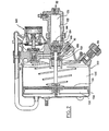
- the braking installation designated by the general reference 10 comprises a tandem master cylinder 12, the structure of which will not be explained in detail.
- This master cylinder is actuated by means of a pedal 14.
- the pressurized liquid coming from the two chambers of the master cylinder borrows two conduits 16 and 18 which lead respectively to a first servomotor 120 and to a second servomotor 220.
- These servomotors are of the vacuum and hydraulic control type as known for example from the patent French published under No. 1 326 576 but as will be explained below, these two servomotors are not identical.
- the two servomotors are connected to a vacuum source 24 by means of a conduit 26 comprising two branches 28 and 30.
- the first servomotor 120 is connected by a conduit 32 to a pair of disc brakes 34 and 36 associated with the front wheels of the vehicle, while the second servomotor 220 is connected by a conduit 38 to a pair of drum brakes 40 and 42 associated with the rear wheels of the vehicle, these drum brakes being of the non-self-locking type.
- the servomotor 120 comprises a cylinder 122 in which a driving piston 124 is slidably mounted, the latter separating the cylinder 122 into a pressure chamber 126 and an assistance and make-up chamber 128. In this latter is projected a push rod 130 likely to drive the engine piston 124 in both directions thanks to a dead-stroke link, the structure of which will not be detailed.
- the push rod 130 is integral with a servomotor piston 132 which divides a housing 134, integral with the cylinder 122, into two compartments 136 and 138, the first being constantly in communication with the source of vacuum and the second can be placed in communication either with the vacuum source or with the atmosphere by means of a control valve 140 as will be explained below.
- the pressure chamber 126 communicates with the conduit 32 for supplying the disc brakes and the assistance chamber 128 communicates with both the conduit 16 for connection with the master cylinder 12 and a control chamber 142 of the valve. controls 140. Finally, the assistance chamber 128 and the pressure chamber 126 can wind communicate through a passage 144 passing through the driving piston 124, this communication being controlled by a valve 146 secured to the rod 130.
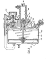
- the booster 220 includes a certain number of identical elements which are designated by the same reference increased by the value 100.
- the pressure chamber 226 of this booster communicates with the supply line 38 for the rear brakes.
- the assistance and production chamber 228 communicates with a reservoir of liquid 250 at atmospheric pressure, and the control chamber 242 of the control valve 240 communicates with the conduit 18 for connection with the master. -cylinder 12.
- the pressurized liquid is transmitted to the servomotors 120 and 220 by the conduits 16 and 18. This results in a pressurization of control chambers 142 and 242 control valves 140 and 240, which then put the compartments 138 and 238 in communication with the atmosphere.
- the servomotor pistons 132 and 232 and the push rods 130 and 230 are then moved towards the cylinders 122 and 222 by first causing the closure of the valves 146 and 246 then the pressurization of the pressure chambers 126 and 226.
- the admission of pressurized fluid into the brakes then causes the vehicle to brake.
- the stroke of the pedal 14 is proportional to the absorption of the two control valves 140 and 240, increased by a slight absorption of the circuit front brake.
- the stroke of the pedal 14 is then proportional to the sole absorption of the front braking circuit.
- the conduit 18 supplies only the control chamber 242
- the conduit 16 supplies, in addition to the control chamber 142, the assistance chamber 128 whose volume increases as a function of the reduction in volume of the pressure chamber 140, therefore as a function of the absorption of the front braking circuit.
- the stroke of the master cylinder remains limited, that is to say ie comparable to that which would be obtained with drum brakes of the self-error type.
- the pressurized fluid coming from the master cylinder directly feeds the disc brakes by passing through the valve 146 of the first servomotor, which ensures minimum braking vehicle regulations, without the effort required by the master cylinder pedal exceeding a tolerated limit.
- tandem master cylinder also makes it possible to ensure minimum braking of the vehicle in the event of the rupture of one or other of the conduits 16 and 18 or of the members which they serve. In this event, assisted braking is maintained on one or other of the brake pairs.
- the two chambers of the master cylinder will also have very different dimensions, the chamber supplying the only control valve. of the actuator being small and the chamber connected to the first actuator being of larger size.
Landscapes
- Engineering & Computer Science (AREA)
- Transportation (AREA)
- Mechanical Engineering (AREA)
- Regulating Braking Force (AREA)
- Braking Systems And Boosters (AREA)
- Transmission Of Braking Force In Braking Systems (AREA)
Applications Claiming Priority (2)
| Application Number | Priority Date | Filing Date | Title |
|---|---|---|---|
| FR8024783 | 1980-11-21 | ||
| FR8024783A FR2494653A1 (fr) | 1980-11-21 | 1980-11-21 | Installation de freinage pour vehicules utilitaires |
Publications (2)
| Publication Number | Publication Date |
|---|---|
| EP0053056A1 EP0053056A1 (fr) | 1982-06-02 |
| EP0053056B1 true EP0053056B1 (fr) | 1984-12-27 |
Family
ID=9248239
Family Applications (1)
| Application Number | Title | Priority Date | Filing Date |
|---|---|---|---|
| EP19810401704 Expired EP0053056B1 (fr) | 1980-11-21 | 1981-10-27 | Installation de freinage pour véhicules utilitaires |
Country Status (3)
| Country | Link |
|---|---|
| EP (1) | EP0053056B1 (OSRAM) |
| DE (1) | DE3167980D1 (OSRAM) |
| FR (1) | FR2494653A1 (OSRAM) |
Families Citing this family (3)
| Publication number | Priority date | Publication date | Assignee | Title |
|---|---|---|---|---|
| DE3715839A1 (de) * | 1987-05-12 | 1988-11-24 | Teves Gmbh Alfred | Bremsschlupfgeregelte kraftfahrzeugbremsanlage |
| FR2631914B1 (fr) * | 1988-05-31 | 1990-08-10 | Bendix France | Dispositif d'assistance au freinage |
| DE4234923A1 (de) * | 1992-10-16 | 1994-04-21 | Teves Gmbh Alfred | Hydraulische Brems- und Lenkbremsanlage für Kraftfahrzeuge |
Family Cites Families (6)
| Publication number | Priority date | Publication date | Assignee | Title |
|---|---|---|---|---|
| US2402344A (en) * | 1944-01-24 | 1946-06-18 | Bendix Aviat Corp | Fluid pressure system |
| FR1326576A (fr) * | 1962-03-30 | 1963-05-10 | Dba Sa | Perfectionnements aux servomoteurs à pression de fluide |
| US3576350A (en) * | 1968-08-29 | 1971-04-27 | Bendix Corp | Antiskid system |
| FR2149265B1 (OSRAM) * | 1971-08-13 | 1975-08-29 | Teves Gmbh Alfred | |
| US3771838A (en) * | 1972-06-29 | 1973-11-13 | Bendix Corp | Synchronized braking system for a tow vehicle trailer |
| US4096696A (en) * | 1976-12-10 | 1978-06-27 | General Motors Corporation | Vehicle power brake system with master booster and slave booster |
-
1980
- 1980-11-21 FR FR8024783A patent/FR2494653A1/fr active Granted
-
1981
- 1981-10-27 DE DE8181401704T patent/DE3167980D1/de not_active Expired
- 1981-10-27 EP EP19810401704 patent/EP0053056B1/fr not_active Expired
Also Published As
| Publication number | Publication date |
|---|---|
| FR2494653B1 (OSRAM) | 1983-01-21 |
| FR2494653A1 (fr) | 1982-05-28 |
| DE3167980D1 (en) | 1985-02-07 |
| EP0053056A1 (fr) | 1982-06-02 |
Similar Documents
| Publication | Publication Date | Title |
|---|---|---|
| EP2475561B1 (fr) | Systeme de freins a servofrein electrique | |
| FR2527154A1 (fr) | Equipement de freinage de train routier | |
| FR2579945A1 (OSRAM) | ||
| FR2602195A1 (fr) | Dispositif de freinage a regulation du glissement de freinage pour vehicule automobile | |
| FR2626831A1 (fr) | Systeme de freinage antiblocage muni d'une regulation du glissement de traction | |
| EP0662894B1 (fr) | Dispositif de freinage assiste a reaction hydraulique ralentie | |
| EP0939713B1 (fr) | Dispositif de freinage assiste a rapport d'assistance variable et hysteresis reduite | |
| FR2559722A1 (fr) | Correcteur de freinage influence par la charge du vehicule | |
| EP0053056B1 (fr) | Installation de freinage pour véhicules utilitaires | |
| EP0340059B1 (fr) | Servomoteur d'assistance au freinage à saut réglable | |
| EP0687230B1 (fr) | Systeme de freinage a trois circuits hydrauliques independants | |
| EP0402183B1 (fr) | Procédé de réglage de la valeur du saut d'un servomoteur d'assistance au freinage | |
| EP0662893B1 (fr) | Dispositif de freinage assiste a reaction hydraulique et saut reglable | |
| FR2611359A1 (fr) | Systeme d'antiblocage | |
| EP0439974B1 (fr) | Système de freinage assisté pour véhicule automobile | |
| EP0939715B1 (fr) | Systeme de feinage assiste a reaction hydraulique amelioree | |
| EP0730538B1 (fr) | Dispositif de freinage assiste a course masquee et a gain garanti | |
| FR2752401A1 (fr) | Installation de freinage a circuits multiples pour vehicules | |
| EP0814988B1 (fr) | Servomoteur pneumatique a reaction pneumatique | |
| EP0999964A1 (fr) | Servomoteur pneumatique a chambre de pilotage | |
| EP0368701B2 (fr) | Système de freinage hydraulique assisté, et servomoteur d'assistance et valve de commande adaptes a un tel système | |
| EP0239471A1 (fr) | Dispositif d'assistance hydraulique | |
| EP1349761B1 (fr) | Servomoteur d'assistance au freinage pour vehicule automobile | |
| FR2781193A1 (fr) | Maitre-cylindre perfectionne a reaction hydraulique et auto-assistance selective | |
| EP0915790B1 (fr) | Systeme de freinage assiste a reaction asservie |
Legal Events
| Date | Code | Title | Description |
|---|---|---|---|
| PUAI | Public reference made under article 153(3) epc to a published international application that has entered the european phase |
Free format text: ORIGINAL CODE: 0009012 |
|
| 17P | Request for examination filed |
Effective date: 19811030 |
|
| AK | Designated contracting states |
Designated state(s): DE GB IT |
|
| ITF | It: translation for a ep patent filed | ||
| GRAA | (expected) grant |
Free format text: ORIGINAL CODE: 0009210 |
|
| AK | Designated contracting states |
Designated state(s): DE GB IT |
|
| REF | Corresponds to: |
Ref document number: 3167980 Country of ref document: DE Date of ref document: 19850207 |
|
| PLBE | No opposition filed within time limit |
Free format text: ORIGINAL CODE: 0009261 |
|
| STAA | Information on the status of an ep patent application or granted ep patent |
Free format text: STATUS: NO OPPOSITION FILED WITHIN TIME LIMIT |
|
| 26N | No opposition filed | ||
| ITTA | It: last paid annual fee | ||
| PGFP | Annual fee paid to national office [announced via postgrant information from national office to epo] |
Ref country code: GB Payment date: 19941018 Year of fee payment: 14 |
|
| PGFP | Annual fee paid to national office [announced via postgrant information from national office to epo] |
Ref country code: DE Payment date: 19941021 Year of fee payment: 14 |
|
| PG25 | Lapsed in a contracting state [announced via postgrant information from national office to epo] |
Ref country code: GB Effective date: 19951027 |
|
| GBPC | Gb: european patent ceased through non-payment of renewal fee |
Effective date: 19951027 |
|
| PG25 | Lapsed in a contracting state [announced via postgrant information from national office to epo] |
Ref country code: DE Effective date: 19960801 |