EP0052535A1 - Boîtier de connecteur électrique muni d'un mécanisme de retenue incorporé - Google Patents
Boîtier de connecteur électrique muni d'un mécanisme de retenue incorporé Download PDFInfo
- Publication number
- EP0052535A1 EP0052535A1 EP81401569A EP81401569A EP0052535A1 EP 0052535 A1 EP0052535 A1 EP 0052535A1 EP 81401569 A EP81401569 A EP 81401569A EP 81401569 A EP81401569 A EP 81401569A EP 0052535 A1 EP0052535 A1 EP 0052535A1
- Authority
- EP
- European Patent Office
- Prior art keywords
- housing
- coupling member
- electrical connector
- fingers
- connector housing
- Prior art date
- Legal status (The legal status is an assumption and is not a legal conclusion. Google has not performed a legal analysis and makes no representation as to the accuracy of the status listed.)
- Granted
Links
Images
Classifications
-
- H—ELECTRICITY
- H01—ELECTRIC ELEMENTS
- H01R—ELECTRICALLY-CONDUCTIVE CONNECTIONS; STRUCTURAL ASSOCIATIONS OF A PLURALITY OF MUTUALLY-INSULATED ELECTRICAL CONNECTING ELEMENTS; COUPLING DEVICES; CURRENT COLLECTORS
- H01R13/00—Details of coupling devices of the kinds covered by groups H01R12/70 or H01R24/00 - H01R33/00
- H01R13/62—Means for facilitating engagement or disengagement of coupling parts or for holding them in engagement
- H01R13/622—Screw-ring or screw-casing
Definitions
- This invention relates to an electrical connector assembly of the type having a first housing having a plurality of electrical contacts mounted therein an adapted to connect to a second housing having a plurality of contacts mounted therein and adapted to mate with the contacts in the first housing, and a coupling member that connects the two housings together.
- the invention eliminates the need in an electrical connector for an extra piece to mount the coupling member to a connector housing by providing a coupling retention mechanism that is integral with the connector housing.
- the invention is an electrical connector characterized by a plurality of resiliently deflectable fingers which extend outwardly from the connector housing to abut against the shoulder of a coupling ring to captivate the coupling ring shoulder between a shoulder on the housing and the deflectable fingers.
- One advantage of the invention is that it provides a new approach to mounting a coupling member to a connector housing.
- Another advantage of the invention is that the retention mechanism eliminates the need for an additional member to mount the coupling member to the housing.
- Another advantage of the invention is that it reduces the time required to assemble the coupling member to the connector housing.
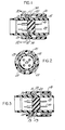
- FIGURE 1 illustrates an electrical connector which generally includes a housing 20, having a plurality of contacts 40 mounted therein, and a coupling nut 10 mounted to the connector housing 20.
- the coupling nut 10 generally includes a plurality of threads in the forward portion for coupling to similar threads on another connector housing, and an annular inwardly extending shoulder 11 which has a rearwardly facing surface 12.
- the connector housing 20 includes an annular shoulder 22 and a plurality of outwardly extending and resiliently deflectable fingers 21.
- the coupling member 10 is mounted to the housing 20 by being captivated between the annular shoulder 22 and the forwardly extending fingers 21.
- a wave washer 30 provides a bias between the annular shoulder ' 22 of the housing and the annular shoulder 11 on the coupling nut 10.
- FIGURE 2 is a cross section of the connector shown in FIGURE 1 and illustrates the arrangement of the forwardly extending fingers 21 which are integral with the connector housing 20.
- the connector housing is molded from a plastic such as torlon (polyamide-imide), or any other similar material that is rigid and tough.
- FIGURE 3 illustrates an alternate embodiment of the invention wherein the integral retention fingers 23 are rearwardly facing to captivate the coupling nut shoulder 11 between the annular shoulder 22 of the housing and the retention fingers 23 extending from the housing 20.
Landscapes
- Connector Housings Or Holding Contact Members (AREA)
- Details Of Connecting Devices For Male And Female Coupling (AREA)
Applications Claiming Priority (2)
| Application Number | Priority Date | Filing Date | Title |
|---|---|---|---|
| US06/206,771 US4362349A (en) | 1980-11-14 | 1980-11-14 | Electrical connector housing with integral retention mechanism |
| US206771 | 1994-03-04 |
Publications (2)
| Publication Number | Publication Date |
|---|---|
| EP0052535A1 true EP0052535A1 (fr) | 1982-05-26 |
| EP0052535B1 EP0052535B1 (fr) | 1984-08-08 |
Family
ID=22767886
Family Applications (1)
| Application Number | Title | Priority Date | Filing Date |
|---|---|---|---|
| EP81401569A Expired EP0052535B1 (fr) | 1980-11-14 | 1981-10-09 | Boîtier de connecteur électrique muni d'un mécanisme de retenue incorporé |
Country Status (5)
| Country | Link |
|---|---|
| US (1) | US4362349A (fr) |
| EP (1) | EP0052535B1 (fr) |
| JP (1) | JPS57109272A (fr) |
| CA (1) | CA1150790A (fr) |
| DE (1) | DE3165422D1 (fr) |
Cited By (2)
| Publication number | Priority date | Publication date | Assignee | Title |
|---|---|---|---|---|
| EP0582771A2 (fr) * | 1992-02-29 | 1994-02-16 | Heinz Schmieder | Connexion à fiche et prise |
| EP2973887A1 (fr) * | 2013-03-15 | 2016-01-20 | Rosenberger Hochfrequenztechnik GmbH & Co. KG | Connecteur |
Families Citing this family (8)
| Publication number | Priority date | Publication date | Assignee | Title |
|---|---|---|---|---|
| DE3318248A1 (de) * | 1983-05-19 | 1984-11-22 | Messerschmitt-Bölkow-Blohm GmbH, 8000 München | Mehrpoliger elektrischer stecker, insbesondere rundstecker |
| DE3424676C1 (de) * | 1984-07-05 | 1985-12-12 | Franz Binder GmbH & Co Elektrische Bauelemente KG, 7107 Neckarsulm | Elektrische Rundkupplung |
| US4622198A (en) * | 1984-08-02 | 1986-11-11 | Allied Corporation | Method of making a coupling nut for an electrical connector having a molded anti-decoupling mechanism |
| US4548458A (en) * | 1984-08-02 | 1985-10-22 | Allied Corporation | Electrical connector having a molded anti-decoupling mechanism |
| US4547032A (en) * | 1984-08-03 | 1985-10-15 | Automation Industries, Inc. | Locking means for a plug and receptacle electrical connector |
| DE69117807T2 (de) * | 1990-05-30 | 1996-10-31 | Whitaker Corp | Geschirmter und isolierter Verbinder |
| JPH0559764U (ja) * | 1992-01-22 | 1993-08-06 | 矢崎総業株式会社 | ネジ締め型コネクタ |
| US9397441B2 (en) | 2013-03-15 | 2016-07-19 | Cinch Connections, Inc. | Connector with anti-decoupling mechanism |
Citations (4)
| Publication number | Priority date | Publication date | Assignee | Title |
|---|---|---|---|---|
| US3917373A (en) * | 1974-06-05 | 1975-11-04 | Bunker Ramo | Coupling ring assembly |
| US4109990A (en) * | 1977-05-26 | 1978-08-29 | The Bendix Corporation | Electrical connector assembly having anti-decoupling mechanism |
| DE2719730A1 (de) * | 1977-05-03 | 1978-11-09 | Akzona Inc | Verbindungsstueck fuer elektrische leitungen |
| GB2005489A (en) * | 1977-09-26 | 1979-04-19 | Bunker Ramo | Coupling assembly for resilient electrical connector components |
Family Cites Families (1)
| Publication number | Priority date | Publication date | Assignee | Title |
|---|---|---|---|---|
| US3947081A (en) * | 1974-11-11 | 1976-03-30 | International Telephone & Telegraph Corporation | Low insertion force circular electrical connector |
-
1980
- 1980-11-14 US US06/206,771 patent/US4362349A/en not_active Expired - Lifetime
-
1981
- 1981-08-20 CA CA000384243A patent/CA1150790A/fr not_active Expired
- 1981-10-09 EP EP81401569A patent/EP0052535B1/fr not_active Expired
- 1981-10-09 DE DE8181401569T patent/DE3165422D1/de not_active Expired
- 1981-11-13 JP JP56181272A patent/JPS57109272A/ja active Pending
Patent Citations (4)
| Publication number | Priority date | Publication date | Assignee | Title |
|---|---|---|---|---|
| US3917373A (en) * | 1974-06-05 | 1975-11-04 | Bunker Ramo | Coupling ring assembly |
| DE2719730A1 (de) * | 1977-05-03 | 1978-11-09 | Akzona Inc | Verbindungsstueck fuer elektrische leitungen |
| US4109990A (en) * | 1977-05-26 | 1978-08-29 | The Bendix Corporation | Electrical connector assembly having anti-decoupling mechanism |
| GB2005489A (en) * | 1977-09-26 | 1979-04-19 | Bunker Ramo | Coupling assembly for resilient electrical connector components |
Cited By (5)
| Publication number | Priority date | Publication date | Assignee | Title |
|---|---|---|---|---|
| EP0582771A2 (fr) * | 1992-02-29 | 1994-02-16 | Heinz Schmieder | Connexion à fiche et prise |
| EP0582771A3 (en) * | 1992-02-29 | 1996-04-03 | Heinz Schmieder | Plug and socket connection |
| EP2973887A1 (fr) * | 2013-03-15 | 2016-01-20 | Rosenberger Hochfrequenztechnik GmbH & Co. KG | Connecteur |
| US9929481B2 (en) | 2013-03-15 | 2018-03-27 | Rosenberger Hochfrequenztechnik Gmbh | Plug-type connector |
| EP2973887B1 (fr) * | 2013-03-15 | 2021-05-26 | Rosenberger Hochfrequenztechnik GmbH & Co. KG | Connecteur |
Also Published As
| Publication number | Publication date |
|---|---|
| EP0052535B1 (fr) | 1984-08-08 |
| US4362349A (en) | 1982-12-07 |
| JPS57109272A (en) | 1982-07-07 |
| DE3165422D1 (en) | 1984-09-13 |
| CA1150790A (fr) | 1983-07-26 |
Similar Documents
| Publication | Publication Date | Title |
|---|---|---|
| EP0052530B1 (fr) | Anneau de couplage de connecteur électrique ayant un ressort integré | |
| CA1153438A (fr) | Bague d'accouplement de connecteur electrique | |
| US6450829B1 (en) | Snap-on plug coaxial connector | |
| EP0073957B1 (fr) | Connecteur électrique blindé | |
| EP0441477B1 (fr) | Assemblage de connecteur électrique montable de façon flottante dans un tableau | |
| US4349241A (en) | Electrical connector assembly having enhanced EMI shielding | |
| US4464001A (en) | Coupling nut having an anti-decoupling device | |
| EP0616387B1 (fr) | Borne de raccordement | |
| US4334730A (en) | Insulated from ground bulkhead adapter | |
| US4359255A (en) | Coupling ring having detent means | |
| US4632482A (en) | Contact for an electrical connector | |
| EP0052535A1 (fr) | Boîtier de connecteur électrique muni d'un mécanisme de retenue incorporé | |
| US4361376A (en) | Electrical connector | |
| US4359256A (en) | Electrical connector coupling member | |
| US4941847A (en) | Electrical connector contact retention system | |
| EP0592519A1 (fr) | Système de borne de raccordement à broches électrique et électronique, et à double usage | |
| US4857007A (en) | Molded environmental seal for electrical connection | |
| EP1170829A2 (fr) | Connecteur électrique avec système d'étanchéité | |
| US4483579A (en) | Electrical connector having improved coupling ring | |
| US4387945A (en) | Electrical connector insert | |
| US4361373A (en) | Electrical connector comprised of plastic | |
| US3845459A (en) | Dielectric sleeve for electrically and mechanically protecting exposed female contacts of an electrical connector | |
| EP0475416B1 (fr) | Connecteur électrique | |
| US4468078A (en) | Forwardly removable coupling ring for an electrical connector | |
| US4461526A (en) | Anti-decoupling mechanism for an electrical connector |
Legal Events
| Date | Code | Title | Description |
|---|---|---|---|
| PUAI | Public reference made under article 153(3) epc to a published international application that has entered the european phase |
Free format text: ORIGINAL CODE: 0009012 |
|
| 17P | Request for examination filed |
Effective date: 19811019 |
|
| AK | Designated contracting states |
Designated state(s): DE FR GB IT |
|
| ITF | It: translation for a ep patent filed |
Owner name: ING. ZINI MARANESI & C. S.R.L. |
|
| GRAA | (expected) grant |
Free format text: ORIGINAL CODE: 0009210 |
|
| AK | Designated contracting states |
Designated state(s): DE FR GB IT |
|
| PG25 | Lapsed in a contracting state [announced via postgrant information from national office to epo] |
Ref country code: FR Free format text: THE PATENT HAS BEEN ANNULLED BY A DECISION OF A NATIONAL AUTHORITY Effective date: 19840808 |
|
| REF | Corresponds to: |
Ref document number: 3165422 Country of ref document: DE Date of ref document: 19840913 |
|
| PGFP | Annual fee paid to national office [announced via postgrant information from national office to epo] |
Ref country code: DE Payment date: 19841018 Year of fee payment: 4 |
|
| PLBE | No opposition filed within time limit |
Free format text: ORIGINAL CODE: 0009261 |
|
| STAA | Information on the status of an ep patent application or granted ep patent |
Free format text: STATUS: NO OPPOSITION FILED WITHIN TIME LIMIT |
|
| 26N | No opposition filed | ||
| EN | Fr: translation not filed | ||
| GBPC | Gb: european patent ceased through non-payment of renewal fee | ||
| PG25 | Lapsed in a contracting state [announced via postgrant information from national office to epo] |
Ref country code: DE Effective date: 19860701 |
|
| PG25 | Lapsed in a contracting state [announced via postgrant information from national office to epo] |
Ref country code: GB Effective date: 19881118 |