EP0052445A1 - Apparatus for detecting and measuring nuclear flux density within a nuclear reactor - Google Patents
Apparatus for detecting and measuring nuclear flux density within a nuclear reactor Download PDFInfo
- Publication number
- EP0052445A1 EP0052445A1 EP81305076A EP81305076A EP0052445A1 EP 0052445 A1 EP0052445 A1 EP 0052445A1 EP 81305076 A EP81305076 A EP 81305076A EP 81305076 A EP81305076 A EP 81305076A EP 0052445 A1 EP0052445 A1 EP 0052445A1
- Authority
- EP
- European Patent Office
- Prior art keywords
- detectors
- detector
- prompt
- nuclear
- reactor
- Prior art date
- Legal status (The legal status is an assumption and is not a legal conclusion. Google has not performed a legal analysis and makes no representation as to the accuracy of the status listed.)
- Ceased
Links
Images

Classifications
-
- G—PHYSICS
- G01—MEASURING; TESTING
- G01T—MEASUREMENT OF NUCLEAR OR X-RADIATION
- G01T3/00—Measuring neutron radiation
-
- G—PHYSICS
- G01—MEASURING; TESTING
- G01T—MEASUREMENT OF NUCLEAR OR X-RADIATION
- G01T3/00—Measuring neutron radiation
- G01T3/006—Measuring neutron radiation using self-powered detectors (for neutrons as well as for Y- or X-rays), e.g. using Compton-effect (Compton diodes) or photo-emission or a (n,B) nuclear reaction
-
- G—PHYSICS
- G21—NUCLEAR PHYSICS; NUCLEAR ENGINEERING
- G21C—NUCLEAR REACTORS
- G21C17/00—Monitoring; Testing ; Maintaining
- G21C17/10—Structural combination of fuel element, control rod, reactor core, or moderator structure with sensitive instruments, e.g. for measuring radioactivity, strain
-
- G—PHYSICS
- G21—NUCLEAR PHYSICS; NUCLEAR ENGINEERING
- G21C—NUCLEAR REACTORS
- G21C17/00—Monitoring; Testing ; Maintaining
- G21C17/10—Structural combination of fuel element, control rod, reactor core, or moderator structure with sensitive instruments, e.g. for measuring radioactivity, strain
- G21C17/108—Measuring reactor flux
-
- Y—GENERAL TAGGING OF NEW TECHNOLOGICAL DEVELOPMENTS; GENERAL TAGGING OF CROSS-SECTIONAL TECHNOLOGIES SPANNING OVER SEVERAL SECTIONS OF THE IPC; TECHNICAL SUBJECTS COVERED BY FORMER USPC CROSS-REFERENCE ART COLLECTIONS [XRACs] AND DIGESTS
- Y02—TECHNOLOGIES OR APPLICATIONS FOR MITIGATION OR ADAPTATION AGAINST CLIMATE CHANGE
- Y02E—REDUCTION OF GREENHOUSE GAS [GHG] EMISSIONS, RELATED TO ENERGY GENERATION, TRANSMISSION OR DISTRIBUTION
- Y02E30/00—Energy generation of nuclear origin
- Y02E30/30—Nuclear fission reactors
Definitions
- This invention relates to apparatus for detecting and measuring nuclear flux density within a nuclear reactor.
- a critical measurement involved in the operation of nuclear reactors is that of measuring in-core neutron flux density.
- Neutron detectors responsive to neutron flux changes are well known and broadly classified into two categories, namely 'prompt responding' and 'delayed response' types.
- the prompt responding detector instantaneously responds to neutron flux changes, while a detector signal of the delayed response detector reaches equilibrium at a significantly measureable time following termination of a neutron flux change.
- Delayed response detectors which are more accurate than the prompt responding types, are used to provide a history of power distributions and variations during power operation modes but do not provide a fast enough signal to be used for safety functions.
- the less accurate prompt responding type detectors on the other hand, must be intermittently or continuously calibrated to ensure an accurate signal. Generally, therefore, the prompt responding detectors have been used outside of the reactor to ensure accessibility for calibration. This, however, inherently leads to a less accurate determination of the incore flux.
- incore prompt responding detectors are used, such detectors are calibrated by using a movable calibration detector system. Calibration detectors remain outside the core until called upon for calibration of fixed incore detectors. The calibration detectors are then inserted by mechanical drive units into the reactor core, by way of calibration tubes of the fixed detector assemblies, and calibration of the fixed incore detectors is accomplished.
- calibration of fixed detectors using a movable calibration system has occurred at infrequent intervals because of wear-and-tear on the movable system.
- a further disadvantage of prior art detectors is that less power is obtained from a given amount of nuclear reactor fuel.
- An increase to optimum power density in a reactor core can be achieved only if the safety system can provide instantaneous protection by responding promptly to power changes in each fuel channel.
- it is important that such incore detectors as are used in the sensing of core power density be capable of prompt response to changes in power density as manifested by changes in local neutron fluxes.
- the output signals from such detectors must necessarily represent incore flux conditions that are instantaneously current rather than flux conditions that actually existed several seconds or more in the past.
- the apparatus for detecting and measuring nuclear flux density within a nuclear reactor, characterised in that the apparatus comprises a plurality of juxtapositioned pairs of prompt responding detectors and delayed response detectors positioned within a nuclear reactor, each detector having an emitter, a sheath and an insulator interposed between the emitter and sheath whereby both detectors of each said pair substantially sense the same neutron flux field, and whereby the delayed response detector of each said pair provides a continuous calibration signal to the corresponding prompt responding detector of said pair.
- the generally more accurate delayed response detectors are thus utilised to provide a generally continuous calibration of the less accurate prompt responding detectors.
- a preferred embodiment of the apparatus comprises a composite incore detector assembly that has pairs of Rhodium-Hafnium detectors spaced axially along the active fuel height of a fuel assembly of the reactor.
- the Hafnium detector is prompt-responding and in conjunction with an online computer system can provide three-dimensional power distributions at a rate in the order of once per second. Under steady-state conditions, the Hafnium signals can easily be calibrated using the power derived from the paired Rhodium signal.
- the individual detectors of the assembly have, as do certain prior art detectors, an emitter, an Inconel sheath, and an insulator interposed between the emitter and sheath. Further, the detectors of the preferred detector assembly have twin leads to eliminate background noise and to increase accuracy.
- the preferred detector assembly is also provided with a calibration tube to provide capability for insertion of a movable detector to obtain continuous axial traces or for intercalibration.
- the assembly may also contain an outlet thermocouple to measure temperature at the top of each instrumented fuel assembly. Further, to maintain the annularity of the detector assembly above those detectors whose emitters are positioned in the lower regions of the core, filler wires are provided between the outer sheath of the detector assembly and the calibration tube.
- the preferred neutron detector assembly thus provides a plurality of paired prompt-responding and delayed-response incore detectors for improving the measuring, calculating, and displaying of core power distributions.
- the output signals from a prompt response detector can be converted to core segment power and local power density values by calibrating the prompt- response detector signal to the signal from its paired delayed-response detector, which is at the same axial core height as the calibrated prompt- response detector.
- the preferred assembly provides reactor operators with more detailed and direct incore flux information to more quickly detect operating anomalies, and enables the elimination of excess conservatisms that necessitate operating nuclear reactors far below their actual physical limits, thus increasing their availability.
- a critical measurement in the opeation of nuclear reactors is that of incore neutron flux density.
- incore neutron flux density A critical measurement in the opeation of nuclear reactors.
- such measurements in selected core locations have been made by delayed-response detectors which have an acceptable degree of accuracy but are slow responding to changes in flux density, having a time constant in the order of one or more minutes, thus prohibiting their use in a reactor control or safety channel and limiting their use to providing a history of power distributions and variations during power operating modes.
- prompt responding sensors having the necessary speed of response for use in a reactor control or safety channel but not having an acceptable degree of initial accuracy, and not possessing a predetermined functional relationship between neutron flux density and signal output.
- prompt responding sensors have been located outside the reactor; or located incore, in which case they must be calibrated by a movable calibration detector system.
- An incore flux density monitoring apparatus 10 as shown in Figure 1 continuously detects and measures core flux distribution during reactor power operation of a nuclear reactor having a core 19.
- the measurements are provided by composite incore detector assemblies 12 located at preselected core radial positions.
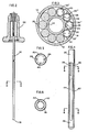
- Each detector assembly 12, as shown in Figures 2 and 3, contains a plurality of juxtapositioned pairs of local flux detectors 20 spaced around a calibration tube 14 and encased in an assembly oversheath 16.
- the oversheath 16 is sealed at the core end 18, for example by welding, and its opposite end is sealed by a high-pressure closure assembly 22.
- the local flux detectors 20 are positioned to measure the flux at different core axial elevations.
- Each detector assembly 12 is inserted into a central instrumentation tube of a fuel assembly 17 through guide tubing 30.
- the guide tubing 30 extends from the bottom of the fuel assembly 17, through a bottom head 13 of the reactor vessel, and terminates in an incore instrument removal tank 15.
- the guide tubing termination and the detector assembly high-pressure closure assembly 22 form a reactor coolant system seal just above the tank floor.
- the guide tubing 30 is an extension of the reactor coolant system.
- the detector assemblies 12 can be inserted and withdrawn through the guide tubing 30 for installation or replacement. During refuelling operations, the detector assemblies are partially withdrawn to allow shuffling of the fuel. After refuelling, the detector assemblies 12 are re-inserted into the original core radial positions and the high-pressure seals are secured.
- the composite incore detector assembly 12 comprises a plurality of pairs of detectors 20 spaced axially along the active fuel height of the core 19.
- One detector of the pair namelly a Hafnium detector 20', is prompt- respnding and can provide prompt three-dimensional power distributions in conjunction with an on-line computer system.
- a slower-responding detector namely a Rhodium detector 20" is paired with the Hafnium detector 20' to minimise required processing.
- Rhodium is self-powered, has only one mode of neutron activation (Rh-103 + onl + Pd-104) and depletes slowly enough so that the depletion correction can be made accurately.
- the Rhodium signal to power conversion is accomplished in an on-line computer (not shown). Under steady-state conditions, the signals of the Hafnium detector 20' can easily be calibrated using the power derived from the paired Rhodium detector signal.
- Both detectors 20' and 20" have twin leads 28 and 29 to eliminate background effects to increase accuracy.
- the lead wires 28 and 29 are, for example, of Inconel.
- fillers 25, generally also of Inconel are positioned above the detectors towards the top of the core to maintain the annularity of the detector assembly 12.
- FIG 4 is an expanded partial sectional view of one of the detectors 20 of the detector assembly 12 of Figure 3 and, together with Figures 5 and 6, shows a detector 20 in more detail.
- the detectors 20 can be seen to comprise an outer sheath 42 enclosing an emitter 44.
- the emitter 44 (the neutron-sensitive element of the detector) is either of Hafnium, in the core of the detectors 20' (for prompt response), or Rhodium, in the case of the detectors 20", (for delayed response).
- the Hafnium 20' detector is paired with a Rhodium detector 20" and the paired detectors are spaced axially along the active fuel height.
- each pair is at a different core height, and although each of the five paired detectors may detect different neutron flux, each individual pair of detectors will essentially see or measure the same flux.
- the conductors or lead wires 28 and 29 are attached to the emitter 44, for example by crimping, and eliminate background noise. Both the lead wires 28 and 29 and the emitter 44 are surrounded by ceramic insulation 46, such as aluminium oxide, within the outer sheath 42. Incoming neutrons can pass easily through the outer sheath 42 and the insulation 46 and are absorbed by the emitter 44.
- a detector assembly in which prompt responding and delayed response self-powered detectors have been placed in the assembly in pairs with the prompt detector of the pair being continuously calibrated from the delayed detector to measure core power distribution axially along the active fuel height.
Landscapes
- Physics & Mathematics (AREA)
- High Energy & Nuclear Physics (AREA)
- Engineering & Computer Science (AREA)
- Health & Medical Sciences (AREA)
- Life Sciences & Earth Sciences (AREA)
- General Physics & Mathematics (AREA)
- Molecular Biology (AREA)
- Spectroscopy & Molecular Physics (AREA)
- Plasma & Fusion (AREA)
- General Engineering & Computer Science (AREA)
- Monitoring And Testing Of Nuclear Reactors (AREA)
- Measurement Of Radiation (AREA)
Applications Claiming Priority (2)
| Application Number | Priority Date | Filing Date | Title |
|---|---|---|---|
| US207049 | 1980-11-14 | ||
| US06/207,049 US4426352A (en) | 1980-11-14 | 1980-11-14 | Composite detector |
Publications (1)
| Publication Number | Publication Date |
|---|---|
| EP0052445A1 true EP0052445A1 (en) | 1982-05-26 |
Family
ID=22768999
Family Applications (1)
| Application Number | Title | Priority Date | Filing Date |
|---|---|---|---|
| EP81305076A Ceased EP0052445A1 (en) | 1980-11-14 | 1981-10-27 | Apparatus for detecting and measuring nuclear flux density within a nuclear reactor |
Country Status (6)
| Country | Link |
|---|---|
| US (1) | US4426352A (enExample) |
| EP (1) | EP0052445A1 (enExample) |
| JP (2) | JPS57149985A (enExample) |
| KR (1) | KR870001094B1 (enExample) |
| CA (1) | CA1172388A (enExample) |
| ES (1) | ES8608717A1 (enExample) |
Cited By (3)
| Publication number | Priority date | Publication date | Assignee | Title |
|---|---|---|---|---|
| FR2611075A1 (fr) * | 1987-02-17 | 1988-08-19 | Westinghouse Electric Corp | Configuration d'assemblage interne au coeur avec enceinte de pression a double paroi pour reacteur nucleaire |
| EP2628022A4 (en) * | 2010-10-14 | 2017-11-01 | AREVA Inc. | Self-calibrating, highly accurate, long-lived, dual rhodium vanadium emitter nuclear in-core detector |
| WO2020092066A1 (en) * | 2018-10-29 | 2020-05-07 | Framatome Inc. | Self-powered in-core detector arrangement for measuring flux in a nuclear reactor core |
Families Citing this family (8)
| Publication number | Priority date | Publication date | Assignee | Title |
|---|---|---|---|---|
| FR2607309B1 (fr) * | 1986-11-26 | 1989-04-28 | Framatome Sa | Conduit de support et de positionnement de dispositifs de mesure dans le coeur d'un reacteur nucleaire |
| US4966747A (en) * | 1987-04-24 | 1990-10-30 | Westinghouse Electric Corp. | Hydro-ball in-core instrumentation system and method of operation |
| FR2632442B1 (fr) * | 1988-06-06 | 1990-09-14 | Framatome Sa | Dispositif de mesure de parametres dans le coeur d'un reacteur nucleaire en service |
| US6061412A (en) * | 1995-10-05 | 2000-05-09 | Westinghouse Electric Company Llc | Nuclear reaction protection system |
| WO2007109535A2 (en) * | 2006-03-16 | 2007-09-27 | Kansas State University Research Foundation | Non-streaming high-efficiency perforated semiconductor neutron detectors, methods of making same and measuring wand and detector modules utilizing same |
| US8958519B2 (en) * | 2012-04-17 | 2015-02-17 | Babcock & Wilcox Mpower, Inc. | Incore instrumentation cable routing and support element for pressurized water reactor |
| JP2016045191A (ja) * | 2014-08-25 | 2016-04-04 | コリア、ハイドロ、アンド、ニュークリア、パワー、カンパニー、リミテッドKorea Hydro & Nuclear Power Co.,Ltd. | 多重熱電対炉内核計測器、それを利用した重大事故後の原子炉内部状態監視システム及び監視方法 |
| CN106710649A (zh) * | 2016-12-12 | 2017-05-24 | 中广核工程有限公司 | 核电厂堆芯核仪表系统 |
Citations (2)
| Publication number | Priority date | Publication date | Assignee | Title |
|---|---|---|---|---|
| US3603793A (en) * | 1969-08-01 | 1971-09-07 | Babcock & Wilcox Co | Radiation detector solid state radiation detection using an insulator between the emitter and collector |
| FR2358641A1 (fr) * | 1976-07-15 | 1978-02-10 | Babcock & Wilcox Co | Transducteur composite |
Family Cites Families (9)
| Publication number | Priority date | Publication date | Assignee | Title |
|---|---|---|---|---|
| CA902273A (en) | 1972-06-06 | The Babcock And Wilcox Company | Radiation detector | |
| DE1539628A1 (de) | 1965-02-08 | 1969-08-28 | Atomenergie Ab | Neutronendetektor |
| BE757887A (fr) | 1969-10-24 | 1971-04-01 | Siemens Ag | Dispositif pour l'instrumentation du reacteurs a eau sous pression |
| FR2081077B1 (enExample) | 1970-03-03 | 1974-03-01 | Framatome Sa | |
| JPS4913598A (enExample) * | 1972-05-22 | 1974-02-06 | ||
| US3760183A (en) | 1972-06-08 | 1973-09-18 | Gen Electric | Neutron detector system |
| FR2356244A1 (fr) | 1976-06-23 | 1978-01-20 | Commissariat Energie Atomique | Procede et dispositif pour detecter et prelocaliser une rupture de gaine dans un reacteur nucleaire a neutrons rapides |
| US4268354A (en) | 1978-10-12 | 1981-05-19 | Westinghouse Electric Corp. | Nuclear reactor in core flux mapping system |
| US4288291A (en) | 1979-05-11 | 1981-09-08 | Whittaker Corporation | Radiation detector for use in nuclear reactors |
-
1980
- 1980-11-14 US US06/207,049 patent/US4426352A/en not_active Expired - Lifetime
-
1981
- 1981-10-27 EP EP81305076A patent/EP0052445A1/en not_active Ceased
- 1981-10-28 KR KR1019810004114A patent/KR870001094B1/ko not_active Expired
- 1981-11-11 JP JP56179873A patent/JPS57149985A/ja active Pending
- 1981-11-13 ES ES507660A patent/ES8608717A1/es not_active Expired
- 1981-11-13 CA CA000390090A patent/CA1172388A/en not_active Expired
-
1987
- 1987-02-16 JP JP1987020078U patent/JPS62146981U/ja active Pending
Patent Citations (2)
| Publication number | Priority date | Publication date | Assignee | Title |
|---|---|---|---|---|
| US3603793A (en) * | 1969-08-01 | 1971-09-07 | Babcock & Wilcox Co | Radiation detector solid state radiation detection using an insulator between the emitter and collector |
| FR2358641A1 (fr) * | 1976-07-15 | 1978-02-10 | Babcock & Wilcox Co | Transducteur composite |
Cited By (5)
| Publication number | Priority date | Publication date | Assignee | Title |
|---|---|---|---|---|
| FR2611075A1 (fr) * | 1987-02-17 | 1988-08-19 | Westinghouse Electric Corp | Configuration d'assemblage interne au coeur avec enceinte de pression a double paroi pour reacteur nucleaire |
| GB2201285A (en) * | 1987-02-17 | 1988-08-24 | Westinghouse Electric Corp | In-core assembly configuration having a dual-wall pressure boundary for nuclear reactor |
| EP2628022A4 (en) * | 2010-10-14 | 2017-11-01 | AREVA Inc. | Self-calibrating, highly accurate, long-lived, dual rhodium vanadium emitter nuclear in-core detector |
| WO2020092066A1 (en) * | 2018-10-29 | 2020-05-07 | Framatome Inc. | Self-powered in-core detector arrangement for measuring flux in a nuclear reactor core |
| US11227697B2 (en) | 2018-10-29 | 2022-01-18 | Framatome Inc. | Self-powered in-core detector arrangement for measuring flux in a nuclear reactor core |
Also Published As
| Publication number | Publication date |
|---|---|
| KR870001094B1 (ko) | 1987-06-04 |
| JPS62146981U (enExample) | 1987-09-17 |
| ES507660A0 (es) | 1986-07-16 |
| ES8608717A1 (es) | 1986-07-16 |
| CA1172388A (en) | 1984-08-07 |
| KR830008183A (ko) | 1983-11-16 |
| US4426352A (en) | 1984-01-17 |
| JPS57149985A (en) | 1982-09-16 |
Similar Documents
| Publication | Publication Date | Title |
|---|---|---|
| US4406011A (en) | Gamma thermometer based reactor core liquid level detector | |
| US4426352A (en) | Composite detector | |
| GB1587969A (en) | Device for measuring local power within a nuclear reactor fuel assembly | |
| KR870010560A (ko) | 코아외 검출기들 및 서모커플들로부터의 출력들을 이용하여 축상전력분포 탐지 및 표시를 하는 방법 및 장치 | |
| US11728057B2 (en) | Nuclear fuel failure protection system | |
| GB2056055A (en) | Measuring the linear heat generation rate of a nuclear reactor fuel pin | |
| JPH0365696A (ja) | 沸騰水型原子炉の熱中性子束検出器用の固定形炉内校正装置 | |
| JP3274904B2 (ja) | 原子炉出力測定装置 | |
| US4637913A (en) | Device for measuring the power in a nuclear reactor | |
| US4200491A (en) | Apparatus and method for detecting power distribution in a nuclear reactor fuel element | |
| RU2092916C1 (ru) | Измерительный канал системы внутриреакторного контроля | |
| EP3908816B1 (en) | Temperature measurement sensor using material with a temperature dependent neutron capture cross section | |
| EP3007176A1 (en) | Convergence reactor in-core detector assembly for core monitoring and protection | |
| US4965041A (en) | Instrument for monitoring the cooling conditions in a light water reactor | |
| US4765943A (en) | Thermal neutron detectors and system using the same | |
| JP2000258586A (ja) | 原子炉出力測定装置 | |
| JP2005172474A (ja) | 原子炉炉心熱出力監視装置 | |
| JPH0587978A (ja) | 原子炉出力計測装置 | |
| US3999067A (en) | High speed radiation scanning technique for simultaneously determining the pitch and eccentricity of an encased oil | |
| JP7269150B2 (ja) | 原子炉出力監視装置 | |
| JPS6138830B2 (enExample) | ||
| Postnikov et al. | New interpretation of signals and in-reactor detector calibration | |
| Seidenkranz et al. | Experiences with prompt self-powered detectors in nuclear reactors of WWER type | |
| JPH05281056A (ja) | 速応性温度計 | |
| JP4429707B2 (ja) | 自動熱的制限値監視装置 |
Legal Events
| Date | Code | Title | Description |
|---|---|---|---|
| PUAI | Public reference made under article 153(3) epc to a published international application that has entered the european phase |
Free format text: ORIGINAL CODE: 0009012 |
|
| AK | Designated contracting states |
Designated state(s): CH DE FR GB IT |
|
| 17P | Request for examination filed |
Effective date: 19820618 |
|
| STAA | Information on the status of an ep patent application or granted ep patent |
Free format text: STATUS: THE APPLICATION HAS BEEN REFUSED |
|
| 18R | Application refused |
Effective date: 19861106 |
|
| RIN1 | Information on inventor provided before grant (corrected) |
Inventor name: WARREN, HOLLAND D. Inventor name: PAULSON, ARNOLD E. Inventor name: BYBEE, RICHARD T. |