EP0052440A2 - Giessen von Trägern aus Spannbeton - Google Patents
Giessen von Trägern aus Spannbeton Download PDFInfo
- Publication number
- EP0052440A2 EP0052440A2 EP81304994A EP81304994A EP0052440A2 EP 0052440 A2 EP0052440 A2 EP 0052440A2 EP 81304994 A EP81304994 A EP 81304994A EP 81304994 A EP81304994 A EP 81304994A EP 0052440 A2 EP0052440 A2 EP 0052440A2
- Authority
- EP
- European Patent Office
- Prior art keywords
- pallet
- anchors
- strands
- casting
- pivots
- Prior art date
- Legal status (The legal status is an assumption and is not a legal conclusion. Google has not performed a legal analysis and makes no representation as to the accuracy of the status listed.)
- Withdrawn
Links
- 238000005266 casting Methods 0.000 title claims abstract description 38
- 239000011513 prestressed concrete Substances 0.000 title claims abstract description 11
- 239000004567 concrete Substances 0.000 claims description 13
- 229910000831 Steel Inorganic materials 0.000 claims description 8
- 239000010959 steel Substances 0.000 claims description 8
- 238000000034 method Methods 0.000 claims description 5
- 239000002184 metal Substances 0.000 claims description 3
- 230000000295 complement effect Effects 0.000 claims description 2
- 230000000694 effects Effects 0.000 claims description 2
- XLYOFNOQVPJJNP-UHFFFAOYSA-N water Substances O XLYOFNOQVPJJNP-UHFFFAOYSA-N 0.000 description 5
- 238000010276 construction Methods 0.000 description 4
- 230000036571 hydration Effects 0.000 description 3
- 238000006703 hydration reaction Methods 0.000 description 3
- 239000000945 filler Substances 0.000 description 2
- 210000002445 nipple Anatomy 0.000 description 2
- 238000004873 anchoring Methods 0.000 description 1
- 238000009434 installation Methods 0.000 description 1
- 238000004519 manufacturing process Methods 0.000 description 1
- 238000011084 recovery Methods 0.000 description 1
- 230000002277 temperature effect Effects 0.000 description 1
Images
Classifications
-
- B—PERFORMING OPERATIONS; TRANSPORTING
- B28—WORKING CEMENT, CLAY, OR STONE
- B28B—SHAPING CLAY OR OTHER CERAMIC COMPOSITIONS; SHAPING SLAG; SHAPING MIXTURES CONTAINING CEMENTITIOUS MATERIAL, e.g. PLASTER
- B28B23/00—Arrangements specially adapted for the production of shaped articles with elements wholly or partly embedded in the moulding material; Production of reinforced objects
- B28B23/02—Arrangements specially adapted for the production of shaped articles with elements wholly or partly embedded in the moulding material; Production of reinforced objects wherein the elements are reinforcing members
- B28B23/04—Arrangements specially adapted for the production of shaped articles with elements wholly or partly embedded in the moulding material; Production of reinforced objects wherein the elements are reinforcing members the elements being stressed
-
- B—PERFORMING OPERATIONS; TRANSPORTING
- B28—WORKING CEMENT, CLAY, OR STONE
- B28B—SHAPING CLAY OR OTHER CERAMIC COMPOSITIONS; SHAPING SLAG; SHAPING MIXTURES CONTAINING CEMENTITIOUS MATERIAL, e.g. PLASTER
- B28B7/00—Moulds; Cores; Mandrels
- B28B7/40—Moulds; Cores; Mandrels characterised by means for modifying the properties of the moulding material
- B28B7/42—Moulds; Cores; Mandrels characterised by means for modifying the properties of the moulding material for heating or cooling, e.g. steam jackets, by means of treating agents acting directly on the moulding material
Definitions
- This invention relates to the casting of prestressed concrete beams.
- prestressed concrete beams are manufactured by casting concrete on to a casting pallet about tensioned prestressing strands which run lengthwise of and are spaced a pre-determined distance above the pallet surface. Hitherto, the ends of the prestressing strands have been connected to ground anchors set a significant depth into the ground in order to withstand the required tension in the strands. In those locations where a considerable anchorage depth is required,.the civil engineering costs involved are significant and, particularly for installations required on site for a limited period, can be exorbitant. Once sited, only limited pallet parts can be salvaged and re-used at different locations. Furthermore, conventional casting pallets are constructed in one length running the entire length of the concrete bed to be cast. Consequently, their use is restricted to the production of a single or. limited number of slab lengths.
- the present invention sets out to provide casting apparatus which avoids the need for ground anchorage for the prestressed wires, has increased pallet length flexibility and enables the entire, or a significant proportion, of the casting apparatus to be dismantled and transported for re-erection at a different location.
- the present invention provides in one aspect apparatus for casting prestressed concrete slabs or beams, which apparatus comprises an elongate casting pallet in which the prestressing strands are anchored between anchors one spaced from each pallet end by means of one or more pivots located at or adjacent the axial centroid of the pallet and below the points of attachment of the strands to the anchors, the forces exerted by the prestressed strands upon the anchors being balanced by balancing forces applied to the anchors at locations below said pivots.
- the balancing forces may be applied by tie bars, rods or strands extending between and attached to the two anchors.
- the balancing forces may be applied separately to each anchor by, for example, jacks bearing on the anchor faces remote from the casting pallet.
- the anchors preferably consist of metal plates and the pivots may extend across the full width of the casting pallet. Alternatively, the pivots may extend over only a portion of the pallet width; two or more in-line pivots may be located at each pallet end.
- the pivots may comprise steel bars of circular or other cross-section which seat in complimentary recesses set in the anchors and in the pallet ends.
- the casting pallet may be supported above ground level by pillars spaced along the length of the pallet.
- means are provided for controllably reducing the balancing forces applied to anchors to effect controlled detensioning of the prestressing strands following hardening or curing of the cast slab or beam.
- the casting pallet may comprise a plurality of endwise-abutting separable lengths.
- the pallet, or each separable pallet length may be provided on its underside with one or . more. lengthwise extending channels for connection to a source of heat exchange medium.
- the or each channel extends over substantially the entire pallet length.
- the heat exchange medium may be water.
- the pallet comprises a plurality of generally parallel ducts secured to the undersurface of a metal plate upon which the concrete bed is to be cast; the ducts may be evenly spaced across the width of the pallet and spaced from one another by means of filler strips.
- heat generated during hydration of the concrete cast onto the elongate pallet may be employed to heat the heat exchange medium flowing through the ducts located beneath and in contact with the pallet surface on which the concrete bed is cast.
- the invention provides apparatus for casting prestressed concrete beams which comprises anchors spaced one from each end ⁇ f an elongate casting pallet by one or more pivots located at or adjacent the axial centroid of the pallet and interconnected firstly by prestressing strands positioned above said pivots and tensioned to impose a pre-determined axial compressive loading upon the pallet, and secondly by a series of tie bars, rods or strands positioned below said pivots and so tensioned that the forces exerted upon the anchors by the prestressing strands are substantially balanced by the forces exerted upon said anchors by the tie bars, rods or strands.
- the invention provides a method of casting prestressed concrete slabs or beams in which concrete is cast on to a casting pallet about tensioned prestressing strands running lengthwise of and spaced a pre- determined distance above the pallet surface, the method comprising the steps of tensioning the prestressing strands between anchors sited one at each.end of the pallet and spaced from the pallet ends by pivots positioned at or adjacent the axial centroid of the pallet, and applying balancing forces to the anchors at locations below said pivots to balance the forces applied to the anchors by the tensioned prestressing wires.
- the prestressing strands may be detensioned following hardening of the cast slab or beam by reducing the balancing forces applied to the anchors.
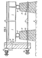
- the casting apparatus illustrated in Figure 1 comprises an elongate casting pallet 1, constructed from a series of abutted sections supported on blocks 2 carried by spaced pillars 3, sited on a hard core base 4.
- the abutting sections may be connected by any conventional means.
- the casting pallet and support blocks may be constructed from steel and the pillars may comprise concrete blocks.
- a steel anchor plate 5 is positioned at each end of the pallet 1 and is spaced from the respective pallet end by a pivot 6 which consists of a steel rod.
- the pivot rod may extend across the entire pallet width or part thereof. Alternatively, two or more such pivot rods may be positioned at each pallet end.
- Each pivot rod 6 seats within complementary recesses, 7, 8 formed respectively in the anchor plate and the pallet end.
- the recess 8 is located so that the pivot 6 is sited at or adjacent the axial centroid of the pallet.
- a series of prestressing strands 9 passes between and are attached to the anchor plates 5.
- the individual strands run lengthwise of the pallet and are sited a pre-determined distance above the pallet surface.
- the strands 9 are conventionally tensioned by one or more jacking devices, 10.
- a series of tie bars, rods or strands, 11 also. passes between and are connected to the anchor plates 5. These ties 11 are positioned below the pivot bar 6 and are maintained in tension by one or more jacking devices 12.
- the ties 11 may comprise steel bars, rods or RSJ's and may pass through bores, 13 set in the pillars 3..
- the abutting pallet sections 1 are mounted on the support blocks 2 with the anchor plates 5 positioned as shown.
- the ties 11 are connected as shown and the prestressing strands 9 are jointly or separately tensioned so that the forces exerted upon the anchor plates 5 by the prestressing strands 9 are balanced by the forces exerted on these plates by the ties 11.
- the apparatus is then ready for casting of a bed of. concrete on the pallet and about the prestressing strands, 9.
- the pallet effectively acts as a strut which is axially compressively loaded by the strands 9 and ties 11.
- the pivots ensure that the load is always axially applied.
- De-tensioning of the prestressing strands, 9 following hardening of the concrete bed can readily be achieved by slackening of the forces applied to the ties 11, by the jacking devices 12. Such slackening causes the anchor plates 5 to pivot about the pivot bars 6 thereby effecting a rapid and even reduction in the tensioning applied to the strands 9.
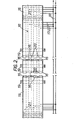
- the casting pallet illustrated consists of several abutting elongated sections each comprising a steel top plate 15 and a plurality of lengthwise extending ducts,.l6.
- the ducts 16 are welded to the undersurface of the plate 15 and are connected through pipes 17,18 to a source of heat exchange medium.
- the source may comprise a reservoir of water.
- the casting pallet is supported above a hard core base by beams 19.
- the pallet ends are anchored in.the manner described above with reference to Figure 1.
- the several heat exchange ducts are spaced evenly across the width of the pallet and are separated from one another by means of filler strips 20. -The ducts are connected to .the pipes 17 through nipples 21 welded to the underside of the pallet. Th 3 upper contour of each of these nipples is cut to a rake angle.
- a bed of concrete is cast on to the top plate 15 of the pallet and the heat evolved during hydration of the cast concrete is conducted from the concrete bed to the water flowing through the ducts 16.
- the heated water may subsequently be transferred to another casting pallet where a heat input is required. Further, the temperature of the water can readily be controlled as it passes from one_to another.
- the apparatus described exhibits several advantages over conventional prestressed concrete casting apparatus, one of which is its ability to be moved entirely or in part and re-sited without the normally high civil engineering costs contingent in ground anchoring of the prestressed strands. Further advantages follow from the ability to de-tension the prestressed wires in the manner described above. Firstly the force required for de-tensioning is relatively small; secondly, since detensioning occurs instantaneously at each end of a hardened slab or beam and within each prestressing strand, unevenly applied loads normally present across the width and along the length of a slab are eliminated.
- the pivot 6 may be a cross-section different from that illustrated.
- the circular- section bars may be replaced by knife-edged pivots or the pallet ends may be shaped so that they themselves provide the pivot abutment to the anchor plates.
- the anchor plates may be so shaped.
Landscapes
- Engineering & Computer Science (AREA)
- Manufacturing & Machinery (AREA)
- Chemical & Material Sciences (AREA)
- Ceramic Engineering (AREA)
- Mechanical Engineering (AREA)
- Manufacturing Of Tubular Articles Or Embedded Moulded Articles (AREA)
- Rod-Shaped Construction Members (AREA)
Applications Claiming Priority (4)
| Application Number | Priority Date | Filing Date | Title |
|---|---|---|---|
| GB8036526 | 1980-11-13 | ||
| GB8036526 | 1980-11-13 | ||
| GB8102306 | 1981-01-26 | ||
| GB8102306 | 1981-01-26 |
Publications (2)
| Publication Number | Publication Date |
|---|---|
| EP0052440A2 true EP0052440A2 (de) | 1982-05-26 |
| EP0052440A3 EP0052440A3 (de) | 1983-07-06 |
Family
ID=26277497
Family Applications (1)
| Application Number | Title | Priority Date | Filing Date |
|---|---|---|---|
| EP81304994A Withdrawn EP0052440A3 (de) | 1980-11-13 | 1981-10-23 | Giessen von Trägern aus Spannbeton |
Country Status (1)
| Country | Link |
|---|---|
| EP (1) | EP0052440A3 (de) |
Cited By (1)
| Publication number | Priority date | Publication date | Assignee | Title |
|---|---|---|---|---|
| US6132394A (en) * | 1994-05-31 | 2000-10-17 | Leiras Oy | Medicament chamber in an inhalation apparatus |
Family Cites Families (1)
| Publication number | Priority date | Publication date | Assignee | Title |
|---|---|---|---|---|
| FR2070943A5 (de) * | 1969-12-12 | 1971-09-17 | Blanquet Andre |
-
1981
- 1981-10-23 EP EP81304994A patent/EP0052440A3/de not_active Withdrawn
Cited By (1)
| Publication number | Priority date | Publication date | Assignee | Title |
|---|---|---|---|---|
| US6132394A (en) * | 1994-05-31 | 2000-10-17 | Leiras Oy | Medicament chamber in an inhalation apparatus |
Also Published As
| Publication number | Publication date |
|---|---|
| EP0052440A3 (de) | 1983-07-06 |
Similar Documents
| Publication | Publication Date | Title |
|---|---|---|
| US2510958A (en) | Composite floor of metal and concrete | |
| JPS6114287B2 (de) | ||
| US3577504A (en) | Method of manufacturing a girder with a web of reinforced and/or prestressed concrete | |
| KR101107826B1 (ko) | 프리캐스트 콘크리트 중공 슬래브(slab)형 횡방향 연결 박스 거더 및 이를 이용한 교량시공방법 | |
| CA2308800A1 (en) | Cellular stirrups and ties for structural members | |
| US8109691B2 (en) | Apparatus and method for on site pouring of pre-stressed concrete structures | |
| US4073115A (en) | Process for the production of a bridge girder sectional cantilever construction | |
| EP0052440A2 (de) | Giessen von Trägern aus Spannbeton | |
| USRE29249E (en) | Precast concrete building construction | |
| US5471812A (en) | Method for fabricating pretensioned concrete structures | |
| GB2088432A (en) | Casting prestressed concrete beams or slabs | |
| KR102199899B1 (ko) | 효율적 응력 분포를 통한 경량화된 교량용 거더 및 이를 이용한 교량의 상부 구조체 시공방법 | |
| US3050283A (en) | Apparatus for depressing cables | |
| GB1402259A (en) | Building method and structure using prefabricated elements | |
| JP2734985B2 (ja) | 片持式シェッドとその施工方法 | |
| JPH08113917A (ja) | 床版用組立体並びにこれを用いた橋梁の施工方法 | |
| JP2513582B2 (ja) | 連続コンクリ―ト舗装工法 | |
| JPS6151524B2 (de) | ||
| CH273887A (de) | Kombinierte Metall- und Beton-Tragkonstruktion. | |
| JPH05132947A (ja) | 法面保護構造物の施工法 | |
| SU635077A1 (ru) | Способ изготовлени стеновых блоков состоавной конструкции | |
| CA1073935A (en) | Weighbridge device | |
| SU987004A1 (ru) | Предварительно напр женна плита сборного дорожного или аэродромного покрыти ,устройство и способ дл ее изготовлени | |
| CN113931365A (zh) | 一种免后浇带的楼盖结构及施工方法 | |
| CS201661B1 (cs) | Kotveni vylehčovaoíoh těles v betonových konstrukoíoh |
Legal Events
| Date | Code | Title | Description |
|---|---|---|---|
| PUAI | Public reference made under article 153(3) epc to a published international application that has entered the european phase |
Free format text: ORIGINAL CODE: 0009012 |
|
| AK | Designated contracting states |
Designated state(s): BE DE FR IT NL SE |
|
| 17P | Request for examination filed |
Effective date: 19821101 |
|
| PUAL | Search report despatched |
Free format text: ORIGINAL CODE: 0009013 |
|
| AK | Designated contracting states |
Designated state(s): BE DE FR IT NL SE |
|
| STAA | Information on the status of an ep patent application or granted ep patent |
Free format text: STATUS: THE APPLICATION HAS BEEN WITHDRAWN |
|
| 18W | Application withdrawn |
Withdrawal date: 19830727 |
|
| RIN1 | Information on inventor provided before grant (corrected) |
Inventor name: SKINNS, PAUL Inventor name: WASS, BRIAN |