EP0052402A2 - Schleppsaugsystem - Google Patents
Schleppsaugsystem Download PDFInfo
- Publication number
- EP0052402A2 EP0052402A2 EP81201239A EP81201239A EP0052402A2 EP 0052402 A2 EP0052402 A2 EP 0052402A2 EP 81201239 A EP81201239 A EP 81201239A EP 81201239 A EP81201239 A EP 81201239A EP 0052402 A2 EP0052402 A2 EP 0052402A2
- Authority
- EP
- European Patent Office
- Prior art keywords
- suction
- pipe
- suction pipe
- vessel
- jib
- Prior art date
- Legal status (The legal status is an assumption and is not a legal conclusion. Google has not performed a legal analysis and makes no representation as to the accuracy of the status listed.)
- Granted
Links
Images


Classifications
-
- E—FIXED CONSTRUCTIONS
- E02—HYDRAULIC ENGINEERING; FOUNDATIONS; SOIL SHIFTING
- E02F—DREDGING; SOIL-SHIFTING
- E02F9/00—Component parts of dredgers or soil-shifting machines, not restricted to one of the kinds covered by groups E02F3/00 - E02F7/00
- E02F9/06—Floating substructures as supports
-
- E—FIXED CONSTRUCTIONS
- E02—HYDRAULIC ENGINEERING; FOUNDATIONS; SOIL SHIFTING
- E02F—DREDGING; SOIL-SHIFTING
- E02F3/00—Dredgers; Soil-shifting machines
- E02F3/04—Dredgers; Soil-shifting machines mechanically-driven
- E02F3/88—Dredgers; Soil-shifting machines mechanically-driven with arrangements acting by a sucking or forcing effect, e.g. suction dredgers
- E02F3/90—Component parts, e.g. arrangement or adaptation of pumps
- E02F3/905—Manipulating or supporting suction pipes or ladders; Mechanical supports or floaters therefor; pipe joints for suction pipes
-
- E—FIXED CONSTRUCTIONS
- E02—HYDRAULIC ENGINEERING; FOUNDATIONS; SOIL SHIFTING
- E02F—DREDGING; SOIL-SHIFTING
- E02F7/00—Equipment for conveying or separating excavated material
- E02F7/04—Loading devices mounted on a dredger or an excavator hopper dredgers, also equipment for unloading the hopper
Definitions
- Suction drag system for a dredging vessel comprising a suction pipe with suction head and a distant suction pump with drive motor, whereby the upper part of the suction pipe behind the pump is pivotably connected to an elbow section, positioned on deck of the ship and giving access to a discharge pipe or chute, which suction pipe near the suction head and/or at a location between said suction head and the elbow section is suspended from derricks or davits by means of which the pipe can be brought outboard and lowered respectively raised and brought inboard, whereby said derricks, the suction pipe, the elbow section and the discharge pipe are components, which can be installed on deck of the ship as separate units.
- An object of the invention is to provide a suction drag system which is also combined from units, which can be mounted on deck, which units, however, can be disconnectable installed onto each type of vessel comprising a hold for receiving dredged material, such as for instance vessels of the type discharging through the bottom, and is especially suited for split hopper vessels.
- a drive unit is positioned onto a supporting frame extending transverse over the hold and connected to the coamings.
- the whole drag system has his own energy source, so that the system can be installed on each type of vessel without the necessity to increase the power of the propelling engines thereof.
- Said power unit preferably consists of a motor with generator and/or a pump, means for supplying energy to the suction pump motor and means for supplying energy to the winches of the derrick units.
- the drive unit preferably comprises operating and controlling means for the dredging device and said means are preferably installed in or on the unit, i.e. in a cabin positioned onto said supporting frame.
- the elbow section of the suction drag system decribed in the Dutch Patent Application 7810861 is supported into guiding elements installed onto the deck of the vessel and movable transverse to the longitudinal axis of said vessel by means of a hydraulical cylinder. Said transverse movement-is necessary when the suction pipe is brought outboard respectively brought inboard. Thereto the elbow section has an elbow, which during the outboard movement realizes the connection with the discharge pipe which is installed at a fixed position above the hold. That means that said connection is not permanent.
- said elbow section is permanently connected to the discharge pipe or chute and comprises a pivot joint with a horizontal axis between the adjacent elbow section and the turn piece connected to the suction pipe, whereby said turn piece is pivotably connected to arms, mounted onto the support frame, which arms together with the pivot joint in the pipe section and with the pivotable connection between the elbow and the supporting frame are forming a parallelogram guiding actuated by said cylinder.
- the pivot joint in the pipe section is preferably realized by means of two yokes, connected to each other and pivotable around a horizontal axis, whereby a hose-piece is extending through said yokes. Because of said hose-piece and because of the parallelogram guiding a permanent connection is possible.
- each derrick unit such, that the winch and winch motor are positioned at one end of the support frame opposite the slewing jib of the derrick and at the position of the outboard slewing jib the cable of said winch is guided by a cable pulley supported by bearings at a distance above the pivot shaft of said slewing jib and by a cable pulley at or near the end of said jib, which jib furthermore comprises means for blocking the jib in the elevated position and in the outboard reaching position and arresting means at the underside or outer side of the suction pipe.
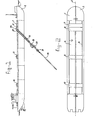
- the vessel illustrated in the above-mentioned Figures is of the type comprising two halves 1 and 2, which are able to carry out a mutually pivotable movement around a longitudinal axis 3.
- the hold 4 has coamings 5 and 6.
- a number of supporting frames is positioned transverse over said hold and connected to said coamings, such as the supporting frame or the drive unit 7, the supporting frame 8 for the elbow section, the supporting frame 9 for the derrick carrying the intermediate suction pipe and the supporting frame 10 for the derrick carrying the drag-head section of said pipe.
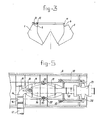
- Each supporting frame is, as is illustrated in Figure 3, at one end connected to the coaming, for instance the coaming 6, by means of a pivot joint 11 and at their other end connected to for instance the coaming 5 by means of a number of roller elements running into a rectangular guiding element 13, such that the supporting frame and the related coaming are able to pivot and move in relation to each other. That is necessary to allow the split movements of the vessel, whereby the supporting frames are maintained in their horizontal position.
- the end 18 of said elbow 14 opposite the discharge pipe 17 is fixedly connected to a yoke 19, which has at 20 a horizontal pivot joint with a yoke 21 fixedly connected to a pipe section 22 giving access to a turn-piece 23.
- the suction pipe 26 is connected to said turn-piece, such that the upper part of said suction pipe 26 is coupled through a pivot joint 27 to said elbow 25.
- suction pipe carries between the upper part 26 and the lower part 28 a suction pump 29 with drive motor 30, whereby the lower part 28 is connected through a universal joint 31.
- the suction pipe is carried at the motor pump unit level by means of cables from the derrick positioned onto the supporting frame 9 and illustrated in Figure 6, whereas the lower end carrying the not illustrated drag-head is by means of cables suspended from a derrick positioned onto the supporting frame 10 and illustrated in Figure 7.
- An eye-bracket 34 realizes the coupling between the elbow 14 and the hydraulic cylinder 35.
- the distance between the pivot axis of the tap 15 and the pivot axis 20 of the yokes 19 and 21 equals the length of the arms 32 between the pivot axis thereof.
- a flexible hose 36 is installed between the bent section 14 and the pipe section 22.
- Figure 6 illustrates the supporting frame 9 with a winch 39 and a drive motor 40 above the movable and pivotable connection with the coaming 5 and at the opposite side a derrick 41 with a jib 43 pivoting around a horizontal shaft 42.
- Said derrick supports a saddle 44 in which the suction pipe can rest as is indicated by the dash-and-dot line 45.
- Said supporting arm is kept in the horizontal position by means of a flexible towing connection 46.
- the cable of the winch 39 is indicated by 47 and runs over the lower pulley 48 of the derrick, an upper pulley 49 of the derrick 41 and a pulley 50 at the end of the arm 43.
- Figure 6 illustrates the situation with lowered pipe.
- the suction pipe When the cable 47 of the winch 39 is pulled in, then the suction pipe will be arrested by the arm 43 whereafter further pulling in of the winch cable 47 will result into an upwards swaying movement of the arm 43 to the position indicated by dash-and-dot lines, in which the suction pipe is brought inboard. Thereafter the suction pipe can be lowered onto the saddle 44.
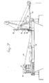
- FIG 7 illustrates the frame 10 with winch 51 and drive motor 52 at one side and the derrick 54 at the other side, which derrick supports a saddle 55 and a jib 56.
- the winch cable 57 runs in the same way as the cable 47 in Figure 6, the difference, however, is that in this case the winch cable also runs over the pulleys 58, 59 of the swell compensator 60 for the drag-head section which swell compensator itself is a known device.
- the supporting frames 7 until 10 can be of a simple construction. They can be embodied with a fixed length adapted to the width dimension between the coamings of the vessel for which they are destined. However, it is also possible to embody them with an adaptable length, for instance by using mutually telescoping longitudinal guiders.
- the discharge pipe 17 can extend over the supporting frames 9 and 10.
Landscapes
- Engineering & Computer Science (AREA)
- Mining & Mineral Resources (AREA)
- Civil Engineering (AREA)
- General Engineering & Computer Science (AREA)
- Structural Engineering (AREA)
- Mechanical Engineering (AREA)
- Ship Loading And Unloading (AREA)
- Jib Cranes (AREA)
Applications Claiming Priority (2)
| Application Number | Priority Date | Filing Date | Title |
|---|---|---|---|
| NL8006209A NL8006209A (nl) | 1980-11-13 | 1980-11-13 | Sleepzuiginrichting. |
| NL8006209 | 1980-11-13 |
Publications (3)
| Publication Number | Publication Date |
|---|---|
| EP0052402A2 true EP0052402A2 (de) | 1982-05-26 |
| EP0052402A3 EP0052402A3 (en) | 1983-03-16 |
| EP0052402B1 EP0052402B1 (de) | 1985-01-16 |
Family
ID=19836173
Family Applications (1)
| Application Number | Title | Priority Date | Filing Date |
|---|---|---|---|
| EP81201239A Expired EP0052402B1 (de) | 1980-11-13 | 1981-10-30 | Schleppsaugsystem |
Country Status (5)
| Country | Link |
|---|---|
| US (1) | US4411079A (de) |
| EP (1) | EP0052402B1 (de) |
| JP (2) | JPS57110585A (de) |
| DE (1) | DE3168391D1 (de) |
| NL (1) | NL8006209A (de) |
Families Citing this family (2)
| Publication number | Priority date | Publication date | Assignee | Title |
|---|---|---|---|---|
| US4716458A (en) * | 1987-03-06 | 1987-12-29 | Heitzman Edward F | Driver-vehicle behavior display apparatus |
| KR100332310B1 (ko) * | 1999-07-28 | 2002-04-12 | 김성천 | 연안 해저 정화용 플랜트 |
Family Cites Families (19)
| Publication number | Priority date | Publication date | Assignee | Title |
|---|---|---|---|---|
| US3198156A (en) * | 1965-08-03 | Bahge construction | ||
| GB191401377A (en) * | 1913-05-22 | 1915-07-08 | Louis Granges | Improvements in or relating to Barges. |
| US1619850A (en) * | 1925-03-12 | 1927-03-08 | Minneapolis Dredging Co | Dredging machine |
| NL72758C (de) | 1934-02-25 | |||
| BE443760A (de) * | 1941-02-03 | |||
| NL74874C (de) * | 1948-12-16 | |||
| US2731741A (en) * | 1950-11-02 | 1956-01-24 | Ellicott Machine Corp | Portable dredge |
| NL77615C (de) * | 1953-06-16 | |||
| US2786284A (en) * | 1953-10-30 | 1957-03-26 | Associated Pipe Line Contracto | Marsh ditcher |
| DE1149632B (de) * | 1960-12-07 | 1963-05-30 | Deggendorfer Werft Eisenbau | Klappschute zum Transport von Baggergut od. dgl. |
| NL113375C (de) * | 1962-03-05 | |||
| NL121927C (nl) * | 1965-02-08 | 1968-12-16 | Vuyk & Zonens Scheepswerven Nv | Onderlossend vaartuig met onder het dek onderling scharnierend verbonden luchtkasten |
| GB1188513A (en) * | 1966-06-20 | 1970-04-15 | Appledore Shipbuilders | Improvements in or relating to Suction Dredgers |
| DE1928271A1 (de) * | 1969-06-03 | 1971-03-11 | Deggendorfer Werft Eisenbau | Hopperbagger |
| DE2203928C2 (de) * | 1972-01-28 | 1974-01-24 | Deggendorfer Werft Und Eisenbau Gmbh, 8360 Deggendorf | Schwimmbagger mit Greiferbaggereinrichtung |
| JPS5332846B2 (de) * | 1973-05-10 | 1978-09-11 | ||
| JPS533592U (de) * | 1976-06-29 | 1978-01-13 | ||
| NL173870C (nl) * | 1978-11-01 | 1986-08-18 | Scheepswerf En Reparatie Bedri | Baggervaartuig met een zuiginrichting. |
| NL7900925A (nl) * | 1979-02-06 | 1980-08-08 | Breejen Beheer | Sleepzuig-baggervaartuig. |
-
1980
- 1980-11-13 NL NL8006209A patent/NL8006209A/nl not_active Application Discontinuation
-
1981
- 1981-10-30 EP EP81201239A patent/EP0052402B1/de not_active Expired
- 1981-10-30 DE DE8181201239T patent/DE3168391D1/de not_active Expired
- 1981-11-10 US US06/320,291 patent/US4411079A/en not_active Expired - Fee Related
- 1981-11-13 JP JP56182172A patent/JPS57110585A/ja active Pending
-
1986
- 1986-10-20 JP JP1986160346U patent/JPS6281653U/ja active Pending
Also Published As
| Publication number | Publication date |
|---|---|
| JPS57110585A (en) | 1982-07-09 |
| US4411079A (en) | 1983-10-25 |
| DE3168391D1 (en) | 1985-02-28 |
| NL8006209A (nl) | 1982-06-01 |
| EP0052402A3 (en) | 1983-03-16 |
| EP0052402B1 (de) | 1985-01-16 |
| JPS6281653U (de) | 1987-05-25 |
Similar Documents
| Publication | Publication Date | Title |
|---|---|---|
| EP0059499A1 (de) | Vertäuungssystem mit einem an dem Meeresboden verankerten schwimmenden Behälter | |
| EP0739290B1 (de) | Ein schiff zur herstellung und/oder zum be-/entladen und zum transport von kohlenwasserstoffen aus offshore feldern, und/oder zum ausführen von bohrlochoperationen | |
| BRPI0621558A2 (pt) | sistema de instalação de tubulação submarina para assentamento de uma tubulação fora-da-costa e/ou instalação de um tubo ascendente submarino, e, métodos de instalação de uma tubulação fora-da-costa e/ou tubo ascendente submarino, e de uma tubulação submarina | |
| US4231398A (en) | Cargo hose to marine tanker connection apparatus | |
| GB1594754A (en) | Articulated fluid loading arm | |
| EP0012518B1 (de) | Schwenkbare Vorrichtung zum Überbringen eines Fluidums | |
| US6736082B2 (en) | Method and system for connecting an underwater buoy to a vessel | |
| EP2218671A1 (de) | Dispositif de transfert d'objets en mer | |
| EP0052402B1 (de) | Schleppsaugsystem | |
| MXPA97006445A (en) | Sism cable recovery system | |
| EP2240362A2 (de) | System zur Kohlenwasserstoffübertragung mit einem schwenkbaren Ausleger | |
| US20250058855A1 (en) | Cable laying vessel | |
| US5520135A (en) | Method and apparatus for hoisitng handling of a load at sea | |
| SE446077B (sv) | Anordning for underhall, reparation, rengoring och/eller malning av fartygssidor | |
| EP0396391A1 (de) | Flüssigkeits- und Materialumschlag auf See und Verfahren zur Durchführung | |
| US4064820A (en) | Apparatus for the marine transshipment of a liquid | |
| CN204493884U (zh) | 一种用于处理海底管道悬跨的落石管抛石装置 | |
| US20040211485A1 (en) | System for transferring oil from an offshore platform to a tanker | |
| KR102952512B1 (ko) | Wtiv과 clv을 융합한 다기능 선박 | |
| GB2065489A (en) | Dredger having oil-collecting arms | |
| EP0185727A1 (de) | Unterwassersystem. | |
| GB2064624A (en) | Apparatus for Performing Work Under Water | |
| RU2186282C2 (ru) | Устройство для воздействия направленной вверх силы на тело, монтажная рама, способ монтажа устройства и способ транспортировки отрезка трубопровода | |
| US4580986A (en) | Mooring system comprising a floating body having storage capacity e.g. a tanker and a buoy anchored to the sea bottom | |
| RU1794791C (ru) | Кабелепрокладочный комплекс |
Legal Events
| Date | Code | Title | Description |
|---|---|---|---|
| PUAI | Public reference made under article 153(3) epc to a published international application that has entered the european phase |
Free format text: ORIGINAL CODE: 0009012 |
|
| AK | Designated contracting states |
Designated state(s): BE DE FR GB NL |
|
| PUAL | Search report despatched |
Free format text: ORIGINAL CODE: 0009013 |
|
| AK | Designated contracting states |
Designated state(s): BE DE FR GB NL |
|
| 17P | Request for examination filed |
Effective date: 19830323 |
|
| GRAA | (expected) grant |
Free format text: ORIGINAL CODE: 0009210 |
|
| AK | Designated contracting states |
Designated state(s): BE DE FR GB NL |
|
| REF | Corresponds to: |
Ref document number: 3168391 Country of ref document: DE Date of ref document: 19850228 |
|
| ET | Fr: translation filed | ||
| PLBE | No opposition filed within time limit |
Free format text: ORIGINAL CODE: 0009261 |
|
| STAA | Information on the status of an ep patent application or granted ep patent |
Free format text: STATUS: NO OPPOSITION FILED WITHIN TIME LIMIT |
|
| 26N | No opposition filed | ||
| PGFP | Annual fee paid to national office [announced via postgrant information from national office to epo] |
Ref country code: NL Payment date: 19871031 Year of fee payment: 7 |
|
| PG25 | Lapsed in a contracting state [announced via postgrant information from national office to epo] |
Ref country code: GB Effective date: 19881030 |
|
| PG25 | Lapsed in a contracting state [announced via postgrant information from national office to epo] |
Ref country code: BE Effective date: 19881031 |
|
| BERE | Be: lapsed |
Owner name: IHC HOLLAND N.V. Effective date: 19881031 |
|
| PG25 | Lapsed in a contracting state [announced via postgrant information from national office to epo] |
Ref country code: NL Effective date: 19890501 |
|
| NLV4 | Nl: lapsed or anulled due to non-payment of the annual fee | ||
| PG25 | Lapsed in a contracting state [announced via postgrant information from national office to epo] |
Ref country code: FR Free format text: LAPSE BECAUSE OF NON-PAYMENT OF DUE FEES Effective date: 19890630 |
|
| PG25 | Lapsed in a contracting state [announced via postgrant information from national office to epo] |
Ref country code: DE Effective date: 19890701 |
|
| GBPC | Gb: european patent ceased through non-payment of renewal fee | ||
| REG | Reference to a national code |
Ref country code: FR Ref legal event code: ST |