EP0052070B1 - Watch with a perpetual date mechanism - Google Patents
Watch with a perpetual date mechanism Download PDFInfo
- Publication number
- EP0052070B1 EP0052070B1 EP81810429A EP81810429A EP0052070B1 EP 0052070 B1 EP0052070 B1 EP 0052070B1 EP 81810429 A EP81810429 A EP 81810429A EP 81810429 A EP81810429 A EP 81810429A EP 0052070 B1 EP0052070 B1 EP 0052070B1
- Authority
- EP
- European Patent Office
- Prior art keywords
- disc
- cam
- date
- years
- months
- Prior art date
- Legal status (The legal status is an assumption and is not a legal conclusion. Google has not performed a legal analysis and makes no representation as to the accuracy of the status listed.)
- Expired
Links
Images
Classifications
-
- G—PHYSICS
- G04—HOROLOGY
- G04B—MECHANICALLY-DRIVEN CLOCKS OR WATCHES; MECHANICAL PARTS OF CLOCKS OR WATCHES IN GENERAL; TIME PIECES USING THE POSITION OF THE SUN, MOON OR STARS
- G04B27/00—Mechanical devices for setting the time indicating means
- G04B27/005—Mechanical devices for setting the time indicating means stepwise or on determined values
-
- G—PHYSICS
- G04—HOROLOGY
- G04B—MECHANICALLY-DRIVEN CLOCKS OR WATCHES; MECHANICAL PARTS OF CLOCKS OR WATCHES IN GENERAL; TIME PIECES USING THE POSITION OF THE SUN, MOON OR STARS
- G04B19/00—Indicating the time by visual means
- G04B19/24—Clocks or watches with date or week-day indicators, i.e. calendar clocks or watches; Clockwork calendars
- G04B19/243—Clocks or watches with date or week-day indicators, i.e. calendar clocks or watches; Clockwork calendars characterised by the shape of the date indicator
- G04B19/247—Clocks or watches with date or week-day indicators, i.e. calendar clocks or watches; Clockwork calendars characterised by the shape of the date indicator disc-shaped
- G04B19/253—Driving or releasing mechanisms
- G04B19/25306—Independent date indicating devices activated by hand or by clockwork, e.g. calendar watches
- G04B19/25313—Independent date indicating devices activated by hand or by clockwork, e.g. calendar watches driven or released by a steady movement
- G04B19/2532—Independent date indicating devices activated by hand or by clockwork, e.g. calendar watches driven or released by a steady movement automatically corrected at the end of mounths having less than 31 days
Definitions
- the present invention relates to a watch with a perpetual calendar mechanism comprising a date disc, means for advancing said disc, means driven at the end of the month by the date disc and acting on said advancing means to determine the size. of the displacement of said date disc, a first cam known as months with annual rotation, and a second cam known as years carrying out a crazy in four years.
- the mechanism uses a rocking control principle of the Longines date disc described in patent CH-A-621,665 and published application CH-A-624,533 G.
- the particularity of this mechanism is that it allows a change of fast date and in both directions of rotation of the hour hand, such as when changing time zones around midnight.
- the leap year correction mechanism comprises according to figs. 1 and 2 a wheel L with four teeth driven at a rate of 1/4 turn per year, from 31.12 to 1.1, by a pin b 3 of the wheel of months B.
- this wheel L doesn ' has no effect.
- its increased diameter exceeds in the February notch b 2 of the wheel B, which prevents the advancement lever H from going down to the normal depth of the notch b 2. This therefore limits the drive of the wheel B by the lever H.
- the mechanism is not symmetrical, so that it operates only in the normal direction of advance of the hands of the timepiece.
- the object of the invention is a watch with a perpetual calendar mechanism allowing corrections of the date, month and year easy and quick to execute.
- the watch according to the invention is characterized in that said means acting on said advancement means comprise said first cam known as months which comprises fingers of different widths to determine different durations of action of said means d advancement and said second cam known as years which comprises fingers juxtaposing with said fingers of the first cam so as to determine said durations of action of the means for advancing the date disc according to the months of 28, 29, 30 or 31 days.
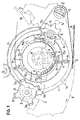
- the mechanism of fig. 1 includes a rocker 1 carrying a pinion 2 which performs a turn in 4 hours and which is secured to a mobile 3 to 4 pins 3a.
- the pinion 2 is driven by a wheel 4 performing 1 revolution in 24 h wearing a finger 5 coming to work once a day, around 24 h, with a boss 6 of the rocker 1.
- the scale 1 includes a lug 9 which works with a cam for the months 17, coaxial with the wheel 4 of 24 h and comprising 48 steps at its periphery, corresponding to 12 times 4 steps ( 28-29, 29-30, 30-31, 31-1 of each month).
- This cam 17 is integral with a wheel 11 of 48 teeth driven tooth by tooth by a pinion 12 of 8 wings fixed on a star 13 of 8 teeth.
- This star 13 is itself driven by four pins or lugs 14 fixed under the calendar disc 8, the pitch between two successive pins being 1/31 of a turn, or 1 pin per day for the days 29-30-31- 1.
- the cam 17 moves one step.
- a tooth 7 of the disc 8 is driven each day by a lug 3a of the mobile 3 when the rocker 1 is controlled by the action of the finger 5 on the boss 6.
- the cam 17, at 48 not, is not trained.
- the step corresponding to day 1 is positioned in front of the lug 9 of the rocker 1.
- the lug 9 is not hampered so that the return movement of the rocker is done normally.
- the cam 17 is not driven.
- the first pin 14 of the disc 8 is located in front of a tooth of the star 13.
- the second pin 14 drives a new tooth of the star 13 and the cam 17 advances again one step. If the 30 must be displayed (every month except February) the lug 9 is not hampered by the cam 17.
- the third pin 14 drives a new tooth of the star 13 and the cam 17 advances a new step. If the 31 must be displayed (January, March, May, July, August, October and December) the pin 9 is not hampered by the cam 17.
- the lug 9 is hampered by one of the fingers 17a of the cam 17.
- the rocker 1 is prevented from withdrawing under the action of the spring 16, and this despite the fact that the finger 5 is released from the boss 6 of the lever 1.
- the pinion 2 and its lugs 3a therefore remain in engagement with the teeth 7 of the calendar disc 8, so that one hour after the jump from 30 to 31 (1/4 turn of pinion 2), a new lug 3a drives a new tooth 7 of the disc 8.
- the 4th pin 14 drives a new star tooth 13 advancing the cam 17 a new step, which displays the 1 of the next month.
- the mechanism described above can make it possible to produce a semi-perpetual calendar, provided that the cam for the months 17 has a finger 17b of obstruction of the lug 9 of sufficient width to allow each year the passage from February 28 to 1 March, a displacement of four steps from the date disc 8.
- the finger should therefore have a width corresponding to four steps from the calendar disc.
- Such a device does not however make it possible to produce a perpetual calendar, which is the subject of the invention, so that, for reasons which will become apparent below, the finger 17b of the cam 17 of FIG. 1 actually has a width corresponding to three steps of the displacement of the calendar disc.
- the novelty consists in including a device programming every four years a end of February with 3 jumps (29-30, 30-31, 31-1), the 29 being displayed normally while the other three years, the program at the end of February orders four jumps (28-29, 29-30, 30-31, 31-1) from calendar disc 8.
- a cam from the 20s coaxial with the cam from the 17 months, and comprising three fingers 21 arranged so as to leave between them angular spaces of 90 °, 90 ° and 180 ° makes a revolution in 4 years, thanks to a wheel 22 (of the same diameter as the wheel 11) coaxial with the cam of the 20s and carrying 48 teeth.
- the cam 20 is integral with the wheel 22.
- This wheel 22 is driven by 2 teeth 23, adjacent, integral and coaxial with the star 13 and the pinion 12. It has been shown above that the star 13 rotates at the rate of 4 teeth per month, i.e. 1 full turn in 2 months.
- the 2 teeth 23 therefore drive 2 teeth of the wheel 22 every two months.
- the cam 20, integral with the wheel 22, therefore performs 1 revolution every 4 years.
- the three fingers 21 of the cam 20 are similar to those 17a of the month cam 17 of FIG. 1. They also perform the same functions, that is to say that when the program requires it, they impede the movement of the lug 9 of the rocker 1, and consequently the return movement of this last.
- the month cam 17 has for the month of February a finger 17b whose width corresponds to three steps of displacement of the calendar disc 8.
- the fourth step necessary for the years normal where February has 28 days, is obtained by one of the teeth 21 of the cam of the 20s coming to be juxtaposed at the end of February with the finger 17b of the cam of the months 17 in order to present to the lug 9 a corresponding width of drag four steps away from rapid movement of the calendar disc.
- the finger 21 of the cam 20 therefore covers one step and the finger 17b of the cam 17 three steps, ie a total of four steps (4 / 48th turn) for the passage from February 28 to March 1 of each normal year. For the leap year when February 29 must be displayed, the finger 21 does not exist on the cam 20, which allows the normal display of the number 29 before making the rapid transition to March 1.
- FIGS. 1 and 2 An examination of FIGS. 1 and 2 shows that the mechanism has symmetry at the level of actuation of the rocker 1 by the finger 5 of the 24-hour wheel acting on the boss 6. There is also a symmetry of the movement of the calendar disc 8 by the pins 3a of the mobile 3 and a third symmetry in the actuation of the star 13 by the pins 14 of the calendar disc. Consequently, the mechanism operates indifferently in the two directions of rotation of the hands, and more particularly in the two directions of rotation of the hour hand, during a change of time zone. Specifically, all time zone changes made during the three-hour period (time during which the display successively indicates 29, 30 and 31) required to change the display from February 28 to March 1 of each normal year simply move the date display forward or backward according to the direction of rotation of the hour hand.
- the above is an important and fundamental characteristic of the perpetual calendar mechanism according to the invention:
- the mechanism is perfectly symmetrical with respect to the direction of rotation of the hands.
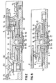
- Figs. 2 and 3 show sections through the mechanism of FIG. 1. Their purpose is to facilitate understanding of the date, month and year setting, for example when changing the battery in an electronic watch.
- the plate or the bridge 24 comprises a pivoting tube 25 on or in which all the coaxial mobiles of the system rotate, that is: the 24-hour wheel 4 secured to the finger 5 and the cam of the 20s on which is fixed the drive wheel 22 to 48 teeth.
- This cam 20 has a barrel 20a pivoting in the tube 25 and supporting a display disc 26 on which the 4 years (3 normal, 1 leap) of the cycle are indicated.
- the month cam 17 carrying the wheel 11 of 48 teeth has a barrel 18 also pivoting about the axis of the tube 25.
- This barrel supports a display disc for the months 27 on which the 12 months of the year are indicated.
- a screw 28 screwed into the barrel 18 ensures assembly of the whole on the tube 25.
- the wheel 11 of the months meshes with the pinion 12 to 8 wings, itself integral with the pinion carrying the 2 teeth 23 which meshes with the wheel 22 .
Abstract
Description
La présente invention concerne une montre avec un mécanisme de quantième perpétuel comprenant un disque de quantième, des moyens d'avencement dudit disque, des moyens entraînés en fin de mois par le disque de quantième et agissant sur lesdits moyens d'avancement pour déterminer la grandeur du déplacement dudit disque de quantième, une première came dite des mois à rotation annuelle, et une seconde came dite des années effectuant un fous en quatre ans.The present invention relates to a watch with a perpetual calendar mechanism comprising a date disc, means for advancing said disc, means driven at the end of the month by the date disc and acting on said advancing means to determine the size. of the displacement of said date disc, a first cam known as months with annual rotation, and a second cam known as years carrying out a crazy in four years.
Le mécanisme utilise un principe de commande à bascule du disque de quantième de Longines décrit dans le brevet CH-A-621 665 et la demande publiée CH-A-624 533 G. La particularité de ce mécanisme est qu'il permet un changement de date rapide et dans les deux sens de rotation de l'aiguille des heures, comme par exemple lors d'un changement de fuseaux horaires effectué aux environs de minuit.The mechanism uses a rocking control principle of the Longines date disc described in patent CH-A-621,665 and published application CH-A-624,533 G. The particularity of this mechanism is that it allows a change of fast date and in both directions of rotation of the hour hand, such as when changing time zones around midnight.
On connaît par le brevet suisse CH-A-574 125 un mécanisme de commande d'un calendrier semi-perpétuel comprenant un disque de quantième actionnant à chaque fin de mois et à l'aide de quatre goupilles, une étoile entraînant une roue solidaire d'une came qui détermine l'angle de pivotement d'une bascule commandant le déplacement, par saut plus ou moins grand, du disque de quantième. Cependant, le mécanisme ne fonctionne que dans le sens normal de rotation des aiguilles et toute mise à la date, aus mois et à l'année est malaisée.We know from Swiss Patent CH-A-574,125 a control mechanism for a semi-perpetual calendar comprising a date disc actuating at the end of each month and using four pins, a star driving a wheel integral with 'A cam which determines the pivot angle of a rocker controlling the movement, by more or less large jump, of the date disc. However, the mechanism only works in the normal direction of rotation of the hands and any date, month and year setting is difficult.
Selon le brevet US-A-527,386, on connaît aussi une pièce d'horlogerie à calendrier perpétuel. Le mécanisme de correction des années bissextiles comprend selon les fig. 1 et 2 une roue L à quatre dents entraînée à raison de 1/4 de tour par année, au passage du 31.12 au 1.1, par une goupille b3 de la roue des mois B. Dans les années normales, cette roue L n'a pas d'effet. Dans les années bissextiles, son diamètre augmenté dépasse dans l'encoche b2 de février de la roue B, ce qui empêche le levier d'avancement H de descendre à la profondeur normale de l'encoche b2. Ceci limite donc l'entrainement de la roue B par le levier H. Cependant, le mécanisme n'est pas symétrique, de sorte qu'il ne fonctionne que dans le sens normal de l'avance des aiguilles de la pièce d'horlogerie.According to US-A-527,386, a timepiece with a perpetual calendar is also known. The leap year correction mechanism comprises according to figs. 1 and 2 a wheel L with four teeth driven at a rate of 1/4 turn per year, from 31.12 to 1.1, by a pin b 3 of the wheel of months B. In normal years, this wheel L doesn ' has no effect. In leap years, its increased diameter exceeds in the February notch b 2 of the wheel B, which prevents the advancement lever H from going down to the normal depth of the notch b 2. This therefore limits the drive of the wheel B by the lever H. However, the mechanism is not symmetrical, so that it operates only in the normal direction of advance of the hands of the timepiece.
Le but de l'invention est une montre avec un mécanisme de quantième perpétuel permettant des corrections de la date, du mois et de l'année faciles et rapides à exécuter.The object of the invention is a watch with a perpetual calendar mechanism allowing corrections of the date, month and year easy and quick to execute.
Pour atteindre ce but, la montre selon l'invention est caractérisée en ce que lesdits moyens agissant sur lesdits moyens d'avancement comprennent ladite première came dite des mois qui comporte des doigts de largeurs différentes pour déterminer des durées d'action différentes desdits moyens d'avancement et ladite seconde came dite des années qui comporte des doigts se juxtaposant avec lesdits doigts de la première came de manière à déterminer lesdites durées d'action des moyens d'avancement du disque de quantième selon les mois de 28, 29, 30 ou 31 jours.To achieve this goal, the watch according to the invention is characterized in that said means acting on said advancement means comprise said first cam known as months which comprises fingers of different widths to determine different durations of action of said means d advancement and said second cam known as years which comprises fingers juxtaposing with said fingers of the first cam so as to determine said durations of action of the means for advancing the date disc according to the months of 28, 29, 30 or 31 days.
L'invention va être décrite ci-après à titre d'exemple et à l'aide du dessin dans lequel:
- la fig. 1 montre le mécanisme de quantième perpétuel selon l'invention,
- la fig. 2 montre une coupe II-II à travers le mécanisme de la fig. 1 et
- la fig. 3 montre une coupe III-III à travers le mécanisme de la fig. 1.
- fig. 1 shows the perpetual calendar mechanism according to the invention,
- fig. 2 shows a section II-II through the mechanism of FIG. 1 and
- fig. 3 shows a section III-III through the mechanism of FIG. 1.
Le mécanisme de la fig. 1 comprend une bascule 1 portant un pignon 2 qui effectue un tour en 4 heures et qui est solidaire d'un mobile 3 à 4 ergots 3a. Le pignon 2 est entraîné par une roue 4 effectuant 1 tour en 24 h portant un doigt 5 venant travailler une fois par jour, aux environs de 24 h, avec un bossage 6 de la bascule 1.The mechanism of fig. 1 includes a rocker 1 carrying a
L'action du doigt 5 sur le bossage 6 a pour effet de provoquer l'engagement des ergots 3a du mobile 3 dans les espaces entre les dents 7 du disque calendrier 8. Ainsi, en 1 heure (correspondant à 1/4 de tour du pignon 2), une dent du disque calendrier a passé et le disque s'est déplacé d'un pas. En réalité, sous l'action du sautoir 10, le saut du disque se produit lorsque la dent 7, entraînée par l'ergot 3a, a parcouru un chemin un peu plus grand que va moitié de son pas. Après le passage du doigt 5, la bascule 1 en pivotant sous l'action d'un ressort de rappel 16, dégage les ergots 3 de la denture du disque calendrier 8. Si aux fins de mois (jours 29, 30, 31, 1) on désire faire avancer ou sauter le disque calendrier de 2, 3 ou 4 pas supplémentaires, soit de 2 pas les mois de 30 jours (du 30 au 31 et du 31 au 1 ), de 4 pas les mois de février (du 28 au 29, 29 au 30, 30 au 31 et 31 au 1 de 3 pas les mois de février des années bissextiles (du 29 au 30, 30 au 31 et 31 au 1 il suffit de provoquer par un programme approprié le maintien de la bascule 1 en position d'action pendant le temps nécessaire, soit 1, 2 ou 3 heures supplémentaires, afin que 2, 3 ou 4 ergots 3a entraînent 2, 3 ou 4 dents supplémentaires 7 du disque calendrier 8.The action of the
Pour réaliser ces fonctions particulières de fin de mois variables, la bascule 1 comporte un ergot 9 qui travaille avec une came des mois 17, coaxiale à la roue 4 de 24 h et comportant 48 pas à son pourtour, correspondant à 12 fois 4 pas (28-29, 29-30, 30-31, 31-1 de chaque mois). Cette came 17 est solidaire d'une roue 11 de 48 dents entraînée dent par dent par un pignon 12 de 8 ailes fixé sur une étoile 13 de 8 dents. Cette étoile 13 est elle-même entraînée par quatre goupilles ou ergots 14 fixés sous le disque calendrier 8, le pas entre deux goupilles successives étant de 1/31 ème de tour, soit 1 goupille par jour pour les jours 29-30-31-1. En conséquence, chaque fois que l'étoile 13 avance d'une dent, la came 17 se déplace d'un pas.To perform these specific functions at the end of the variable month, the scale 1 includes a lug 9 which works with a cam for the
Fonctionnement du mécanisme de quantième perpétuelOperation of the perpetual calendar mechanism
Pendant 28 jours, le système fonctionne normalement, une dent 7 du disque 8 est entraînée chaque jour par un ergot 3a du mobile 3 lorsque la bascule 1 est commandée par l'action du doigt 5 sur le bossage 6. La came 17, à 48 pas, n'est pas entraînée. Le pas correspondant au jour 1 est positionné devant l'ergot 9 de la bascule 1. Lors du pivotement de la bascule 1 autour de la goupille 15, l'ergot 9 n'est pas entravé de sorte que le mouvement de retour de la bascule se fait normalement. Pendent ces 28 jours, la came 17 n'est pas entraînée. Au moment du passage du 28 au 29, la première goupille 14 du disque 8 se trouve devant une dent de l'étoile 13. Lors du saut du 28 au 29, provoqué par un ergot 3a du mobile 3, la première goupille 14 entraîne une dent 13a de l'étoile 13 et la came 17 avance d'un pas. Si le 29 doit être affiché (tous les mois sauf février), l'ergot 9 n'est pas entravé par la came 17.For 28 days, the system is operating normally, a
Au saut du 29 au 30, provoqué par un ergot 3a, la deuxième goupille 14 entraîne une nouvelle dent de l'étoile 13 et la came 17 avance encore d'un pas. Si le 30 doit être affiché (tous les mois sauf février) l'ergot 9 n'est pas entravé par la came 17.At the jump from 29 to 30, caused by a
Au saut du 30 au 31, provoqué par un ergot 3a, la troisième goupille 14 entraîne une nouvelle dent de l'étoile 13 et la came 17 avance d'un nouveau pas. Si le 31 doit être affiché (mois de janvier, mars, mai, juillet, août, octobre et décembre) l'ergot 9 n'est pas entravé par la came 17.At the jump from 30 to 31, caused by a
Si le 31 ne doit pas être affiché, (mois de février, avril, juin, septembre et novembre), l'ergot 9 est entravé par un des doigts 17a de la came 17. La bascule 1 est empêchée de se retirer sous l'action du ressort 16, et ceci malgré que le doigt 5 soit dégagé du bossage 6 de la bascule 1. Le pignon 2 et ses ergots 3a restent donc en prise avec les dents 7 du disque calendrier 8, de sorte qu'une heure après le saut du 30 au 31 (1/4 de tour du pignon 2), un nouvel ergot 3a entraîne une nouvelle dent 7 du disque 8. A cet instant, la 4e goupille 14 entraîne une nouvelle dent de l'étoile 13 faisant avancer la came 17 d'un nouveau pas, ce qui affiche le 1 du prochain mois. Dans cette position de la came 17, l'ergot 9 est libéré et la bascule 1 peut se retirer normalement, les ergots 3a n'entraînant plus les dents 7 du disque 8. Pendant les 28 prochains jours, la came 17 sera au repos, le disque 8 n'ayant pendant cette période aucune goupille 14 à présenter à l'étoile 13. Pour les mois à 30 jours, la came 17 possède donc un doigt 17a d'entrave pour l'ergot 9.If the 31 should not be displayed (February, April, June, September and November), the lug 9 is hampered by one of the
Le mécanisme décrit ci-dessus peut permettre de réaliser un calendrier semi-perpétuel, pour autant que la came des mois 17 comporte un doigt 17b d'entrave de l'ergot 9 de largeur suffisante pour permettre chaque année le passage du 28 février au 1 mars, soit un déplacement de quatre pas du disque de quantième 8. Le doigt devrait donc avoir une largeur correspondante à quatre pas du disque calendrier. Un tel dispositif ne permet cependant pas de réaliser un quantième perpétuel, objet de l'invention, de sorte que, pour des raisons qui seront apparentes plus loin, le doigt 17b de la came 17 de la fig. 1 a en réalité une largeur correspondante à trois pas du déplacement du disque calendrier.The mechanism described above can make it possible to produce a semi-perpetual calendar, provided that the cam for the
Pour réaliser un calendrier perpétuel, il faut une commande programmée de tous les mois sur le cycle de quatre ans, y compris l'année bissextile.To make a perpetual calendar, you need a programmed order every month on the four-year cycle, including the leap year.
En prenant comme base le mécanisme décrit plus haut, la nouveauté consiste à inclure un dispositif programmant tous les quatre ans une fin de février à 3 sauts (29-30, 30-31, 31-1), le 29 étant affiché normalement alors que les trois autres années, le programme de fin février commande quatre sauts (28-29, 29-30, 30-31, 31-1) du disque calendrier 8.Taking as a basis the mechanism described above, the novelty consists in including a device programming every four years a end of February with 3 jumps (29-30, 30-31, 31-1), the 29 being displayed normally while the other three years, the program at the end of February orders four jumps (28-29, 29-30, 30-31, 31-1) from calendar disc 8.
Pour un tel système, il est nécessaire d'avoir un élément susceptible de différencier le février des années bissextiles des févriers des trois années normales. Dans ce but, une came des années 20, coaxiale à la came des mois 17, et comportant trois doigts 21 disposées de manière à laisser entre eux des espaces angulaires de 90°, 90° et 180° effectue un tour en 4 ans, grâce à une roue 22 (de même diamètre que la roue 11) coaxiale à la came des années 20 et portant 48 dents. La came 20 est solidaire de la roue 22. Cette roue 22 est entraînée par 2 dents 23, adjacentes, solidaires et coaxiales à l'étoile 13 et au pignon 12. Il a été montré plus haut que l'étoile 13 tourne à raison de 4 dents par mois soit 1 tour complet en 2 mois. Les 2 dents 23 entraînent donc 2 dents de la roue 22 tous les deux mois. La came 20, solidaire de la roue 22, effectue donc bien 1 tour tous les 4 ans.For such a system, it is necessary to have an element capable of differentiating February from leap years from February three normal years. For this purpose, a cam from the 20s, coaxial with the cam from the 17 months, and comprising three
Les tois doigts 21 de la came 20 sont semblables à ceux 17a de la came des mois 17 de la fig. 1. Ils réalisent également les mêmes fonctions, c'est-à-dire que quand le programme l'exige, ils viennent entraver le mouvement de l'ergot 9 de la bascule 1, et en con- séequence le mouvement de retour de cette dernière.The three
Dans cette réalisation, et comme nous l'avons déjà mentionné plus haut, la came des mois 17 comporte pour le mois de février un doigt 17b dont la largeur correspond à trois pas de déplacement du disque calendrier 8. Le quatrième pas nécessaire pour les années normales où février a 28 jours, est obtenu par une des dents 21 de la came des années 20 venant se juxtaposer à fin février au doigt 17b de la came des mois 17 afin de présenter à l'ergot 9 une largeur d'entrave correspondante à quatre pas de déplacement rapide du disque calendrier.In this embodiment, and as we have already mentioned above, the
Au saut du 28 au 29 la came 20 présente donc un doigt 21 entravant l'ergot 9 de la bascule 1; le 29 saute donc à minuit. Au passage du 29 au 30 (qui ne doit pas être affiché), c'est le doigt 17b de la came 17 qui entrave l'ergot 9 et le 30 saute donc 1 heure après le 29. Au passage du 30 au 31 (qui ne doit pas être affiché) le doigt 17b entravant l'ergot 9 est toujours présent et le 31 saute donc 2 heures après le 29. Au passage du 31 au 1 (qui doit être affiché), le doigt 17b entravant l'ergot 9 est encore en place, de sorte que le disque 8 saute du 31 au 1 trois heures après le saut du 28 du 29.When jumping from 28 to 29 the
Le doigt 21 de la came 20 couvre donc un pas et le doigt 17b de la came 17 trois pas, soit au total quatre pas (4/48ème tour) pour le passage du 28 février au 1 mars de chaque année normale. Pour l'année bissextile où le 29 février doit être affiché, le doigt 21 n'existe pas sur la came 20, ce qui permet l'affichage normal du chiffre 29 avant d'effectuer le passage rapide au 1 mars.The
Un examen des figures 1 et 2 montre que le mécanisme présente une symétrie au niveau de l'actionnement de la bascule 1 par le doigt 5 de la roue de 24 h agissant sur le bossage 6. Il existe aussi une symétrie du déplacement de disque calendrier 8 par les ergots 3a du mobile 3 et une troisième symétrie dans l'actionnement de l'étoile 13 par les goupilles 14 du disque calendrier. En conséquence, le mécanisme fonctionne indifféremment dans les deux sens de rotation des aiguilles, et plus particulièrement dans les deux sens de rotation de l'aiguille des heures, lors d'un changement de fuseau horaire. Plus précisément, tous les changements de fuseau horaire effectués pendant la période de trois heures (temps pendant lequel l'affichage indique successivement 29, 30 et 31 ) nécessaire pour faire passer l'affichage du 28 février au 1 mars de chaque année normale font simplement avancer ou reculer l'affichage de la date selon le sens de rotation de l'aiguille des heures.An examination of FIGS. 1 and 2 shows that the mechanism has symmetry at the level of actuation of the rocker 1 by the
Ce qui précède est une caractéristique importante et fondamentale du mécanisme de quantième perpétuel selon l'invention: Le mécanisme est parfaitement symétrique par rapport au sens de rotation des aiguilles.The above is an important and fundamental characteristic of the perpetual calendar mechanism according to the invention: The mechanism is perfectly symmetrical with respect to the direction of rotation of the hands.
Les fig. 2 et 3 montrent des coupes à travers le mécanisme de la fig. 1. Elles ont pour but de faciliter la compréhension de la mise à la date, au mois et à l'année, par exemple lors d'un changement de pile dans une montre électronique.Figs. 2 and 3 show sections through the mechanism of FIG. 1. Their purpose is to facilitate understanding of the date, month and year setting, for example when changing the battery in an electronic watch.
Dans ce mécanisme, la platine ou le pont 24 comporte un tube de pivotement 25 sur ou dans lequel tournent tous les mobiles coaxiaux du système, soit: la roue de 24 heures 4 solidaire du doigt 5 et la came des années 20 sur laquelle est fixée la roue d'entraînement 22 à 48 dents. Cette came 20 possède un canon 20a pivotant dans le tube 25 et supportant un disque d'affichage 26 sur lequel sont indiquées les 4 années (3 normales, 1 bissextile) du cycle. La came des mois 17 portant la roue 11 de 48 dents possède un canon 18 pivotant aussi autour de l'axe du tube 25. Ce canon supporte un disque d'affichage des mois 27 sur lequel sont indiqués les 12 mois de l'année. Une vis 28 vissée dans le canon 18 assure l'assemblage du tout sur le tube 25. La roue 11 des mois engrène avec le pignon 12 à 8 ailes, lui-même solidaire du pignon porteur des 2 dents 23 qui engrène avec la roue 22.In this mechanism, the plate or the
Pour une mise à la date au mois et à l'année du calendrier perpétuel lors d'un changement de pile, par exemple, on procède de a manière suivante:
- a) Mise à la date du jour voulu par entraînement de la roue de 24 heures donc des doigts 3a du mobile 3 qui entraînent les dents 7 du disque calendrier 8. La roue de 24 h est actionnée manuellement par la couronne de la pièce d'horlogerie, de préférence dans sa position spéciale prévue pour les changements de fuseau horaire. Dans cette position, la couronne n'entraîne que la rotation de l'aiquille des heures.
- b) Entraînement en rotation du disque des mois 27 qui, lui, entraîne par le pignon double 12-23, la
roue 22 des années dans le rapport 4 à 1. Il suffit donc de faire tourner manuellement le disque des mois 27 supporté par la came des mois 17 jusqu'à ce que le disque des années 26 supporté par la came des années 20 arrive dans la bonne année (repère fixe sur le pont 24) relativement à l'année bissextile. La rotation du disque 27 est alors poursuivie jusqu'au mois désiré (par rapport au repère fixe).
- a) Setting the date of the desired day by driving the 24-hour wheel so the
fingers 3a of the mobile 3 which drive theteeth 7 of the calendar disc 8. The 24-hour wheel is manually actuated by the crown of the coin watchmaking, preferably in its special position intended for time zone changes. In this position, the crown only causes the hour hand to rotate. - b) Rotation drive of the
month disc 27 which, for its part, drives by the double pinion 12-23, thewheel 22 of the years in the ratio 4 to 1. It therefore suffices to manually rotate themonth disc 27 supported by the cam of the 17 months until the disc of the 26s supported by the cam of the 20s arrives in the correct year (fixed mark on the bridge 24) relative to the leap year. The rotation of thedisc 27 is then continued until the desired month (relative to the fixed mark).
L'actionnement manuel du disque des mois 27 ne donne lieu à aucune difficulté puisque lors d'une mise à la date et à l'année ou lors d'un changement de pile dans une montre électronique, le fond de la boîte est enlevé. On a donc accès direct au disque 27 situé en regard du fond.The manual actuation of the
La manipulation du disque des mois ne doit cependant être effectuée que lorsque la bascule a été mise en position "écartée" (comme à minuit par le doigt 5 agissant sur le bossage 6), par un dispositif simple non représenté, afin que les doigts 17a, 17b et 21 des cames 17 et 20 ne soient pas gênés dans leur mouvement par l'ergot 9.The handling of the month disc should however only be carried out when the rocker has been placed in the "apart" position (as at midnight by the
Ce qui précède montre que la mise à la date, au mois et à l'année est facile et rapide à exécuter. Ein raison de la symétrie du mécanisme, la couronne et le disque des mois 27 peuvent être actionnés dans les deux sens de rotation, ce qui facilite encore l'opération.The above shows that setting the date, month and year is easy and quick to perform. Because of the symmetry of the mechanism, the crown and the 27 month disc can be actuated in both directions of rotation, which further facilitates the operation.
Claims (8)
Applications Claiming Priority (2)
| Application Number | Priority Date | Filing Date | Title |
|---|---|---|---|
| CH8272/80 | 1980-11-07 | ||
| CH827280A CH642809B (en) | 1980-11-07 | 1980-11-07 | WATCH WITH A PERPETUAL CALENDAR MECHANISM. |
Publications (2)
| Publication Number | Publication Date |
|---|---|
| EP0052070A1 EP0052070A1 (en) | 1982-05-19 |
| EP0052070B1 true EP0052070B1 (en) | 1985-02-13 |
Family
ID=4337791
Family Applications (1)
| Application Number | Title | Priority Date | Filing Date |
|---|---|---|---|
| EP81810429A Expired EP0052070B1 (en) | 1980-11-07 | 1981-10-29 | Watch with a perpetual date mechanism |
Country Status (5)
| Country | Link |
|---|---|
| US (1) | US4427300A (en) |
| EP (1) | EP0052070B1 (en) |
| JP (1) | JPS57108783A (en) |
| CH (1) | CH642809B (en) |
| DE (1) | DE3168952D1 (en) |
Families Citing this family (14)
| Publication number | Priority date | Publication date | Assignee | Title |
|---|---|---|---|---|
| CH649433GA3 (en) * | 1983-08-30 | 1985-05-31 | ||
| CH658188A5 (en) * | 1984-03-23 | 1986-10-31 | Ciba Geigy Ag | STORAGE STABLE QUICK DISASSEMBLING PHARMACEUTICAL PRESSELS. |
| US4852030A (en) * | 1984-09-24 | 1989-07-25 | Westinghouse Electric Corp. | Time-of-use-meter with a calendar of cyclic events |
| CH672222B5 (en) * | 1987-11-11 | 1990-05-15 | Rolex Montres | |
| US5689476A (en) * | 1995-05-16 | 1997-11-18 | Leach; Terrence T. | Telephone cost monitor |
| ES2149058B1 (en) * | 1996-11-27 | 2001-05-01 | Dolcet Cavero Antoni | PERPETUAL CALENDAR MECHANISM |
| US7027361B2 (en) * | 2003-11-18 | 2006-04-11 | Timex Group B.V. | Perpetual calendar for a timepiece |
| ATE337574T1 (en) * | 2004-06-28 | 2006-09-15 | Grisogono S A De | DEVICE FOR LARGE DATE DISPLAY |
| DE102005014328B3 (en) * | 2005-03-24 | 2006-07-20 | Lange Uhren Gmbh | Calendar date circuit for clock, has latch sliding during pivoting of lever, where pivoting parts are switched at position where sprocket is placed in lever normal position and in tactile finger position, at raising of month level slide |
| EP2565729B1 (en) * | 2011-08-30 | 2018-01-31 | Breitling AG | Calendar mechanism |
| CH711749A1 (en) * | 2015-11-13 | 2017-05-15 | Gfpi Sa | Calendar mechanism for timepiece. |
| EP3173878B1 (en) * | 2015-11-26 | 2021-05-26 | Rolex Sa | Timepiece calendar system |
| EP3193217A1 (en) * | 2016-01-18 | 2017-07-19 | ETA SA Manufacture Horlogère Suisse | Timepiece movement comprising an analog display |
| EP3671366B1 (en) * | 2018-12-21 | 2022-04-20 | ETA SA Manufacture Horlogère Suisse | Device for displaying a series of periodic events that form an annual cycle and timepiece comprising such a display device |
Family Cites Families (6)
| Publication number | Priority date | Publication date | Assignee | Title |
|---|---|---|---|---|
| US387005A (en) * | 1888-07-31 | nilson | ||
| US527386A (en) * | 1893-10-12 | 1894-10-09 | Calendar-clock | |
| CH318902A (en) * | 1954-02-05 | 1957-01-31 | Bringolf John | Calendar timepiece |
| CH574125B5 (en) * | 1972-04-05 | 1976-03-31 | Suisse Horlogerie | |
| CH621665GA3 (en) * | 1977-05-27 | 1981-02-27 | ||
| CH624533GA3 (en) * | 1979-05-02 | 1981-08-14 | Watch with analog display of the time and calendar |
-
1980
- 1980-11-07 CH CH827280A patent/CH642809B/en unknown
-
1981
- 1981-10-29 DE DE8181810429T patent/DE3168952D1/en not_active Expired
- 1981-10-29 EP EP81810429A patent/EP0052070B1/en not_active Expired
- 1981-11-03 US US06/317,877 patent/US4427300A/en not_active Expired - Fee Related
- 1981-11-06 JP JP56178267A patent/JPS57108783A/en active Pending
Also Published As
| Publication number | Publication date |
|---|---|
| JPS57108783A (en) | 1982-07-06 |
| EP0052070A1 (en) | 1982-05-19 |
| DE3168952D1 (en) | 1985-03-28 |
| CH642809B (en) | |
| CH642809GA3 (en) | 1984-05-15 |
| US4427300A (en) | 1984-01-24 |
Similar Documents
| Publication | Publication Date | Title |
|---|---|---|
| EP0052070B1 (en) | Watch with a perpetual date mechanism | |
| EP1677165B1 (en) | Timepiece with a mechanical Chinese calendar | |
| EP3009893B1 (en) | Differential perpetual calendar | |
| WO2007144268A2 (en) | Timepiece with a calendar number mechanism | |
| WO2015062839A2 (en) | Hijri calendar | |
| EP0987609B1 (en) | Annual calendar mechanism for clockwork-movement | |
| EP1012675B1 (en) | Train of clockwork with perpetual julian date | |
| EP1631864B1 (en) | Date indicating mechanism for timepiece | |
| EP0606576A1 (en) | Moslem calendar | |
| WO2001048568A1 (en) | Annual, perpetual or centennial calendar mechanism | |
| WO1998044394A1 (en) | Time-setting mechanism for clock movement with perpetual julian date | |
| EP1660952B1 (en) | Date corrector | |
| EP1321831B1 (en) | Jump-dial watch and mechanism for quick update of time zone | |
| EP0537515A1 (en) | Display device for a timepiece | |
| EP4189489B1 (en) | Time setting method of a watch in a horological unit "sympathique" | |
| EP3731027B1 (en) | Device for displaying the calendar as well as the time of sunrise and/or the time of sunset | |
| CH691149A5 (en) | Watch mechanism for setting the time, date, month and year, which only uses gear wheels without levers | |
| CH717703B1 (en) | Nice set of clocks. | |
| CH717699B1 (en) | Nice set of clocks. | |
| CH717701B1 (en) | Nice set of clocks. | |
| CH717700B1 (en) | Nice set of clocks. | |
| CH717702B1 (en) | Nice set of clocks. | |
| CH717697B1 (en) | Nice set of clocks. | |
| EP3731028A1 (en) | Device for displaying summer time as well as the time of sunrise and/or the time of sunset | |
| CH718804A1 (en) | Perpetual or annual calendar mechanism. |
Legal Events
| Date | Code | Title | Description |
|---|---|---|---|
| PUAI | Public reference made under article 153(3) epc to a published international application that has entered the european phase |
Free format text: ORIGINAL CODE: 0009012 |
|
| AK | Designated contracting states |
Designated state(s): DE FR GB IT |
|
| 17P | Request for examination filed |
Effective date: 19820913 |
|
| GRAA | (expected) grant |
Free format text: ORIGINAL CODE: 0009210 |
|
| AK | Designated contracting states |
Designated state(s): DE FR GB IT |
|
| PG25 | Lapsed in a contracting state [announced via postgrant information from national office to epo] |
Ref country code: IT Free format text: LAPSE BECAUSE OF FAILURE TO SUBMIT A TRANSLATION OF THE DESCRIPTION OR TO PAY THE FEE WITHIN THE PRESCRIBED TIME-LIMIT;WARNING: LAPSES OF ITALIAN PATENTS WITH EFFECTIVE DATE BEFORE 2007 MAY HAVE OCCURRED AT ANY TIME BEFORE 2007. THE CORRECT EFFECTIVE DATE MAY BE DIFFERENT FROM THE ONE RECORDED. Effective date: 19850213 |
|
| REF | Corresponds to: |
Ref document number: 3168952 Country of ref document: DE Date of ref document: 19850328 |
|
| PLBE | No opposition filed within time limit |
Free format text: ORIGINAL CODE: 0009261 |
|
| STAA | Information on the status of an ep patent application or granted ep patent |
Free format text: STATUS: NO OPPOSITION FILED WITHIN TIME LIMIT |
|
| 26N | No opposition filed | ||
| PGFP | Annual fee paid to national office [announced via postgrant information from national office to epo] |
Ref country code: DE Payment date: 19881017 Year of fee payment: 8 |
|
| PG25 | Lapsed in a contracting state [announced via postgrant information from national office to epo] |
Ref country code: GB Effective date: 19891029 |
|
| GBPC | Gb: european patent ceased through non-payment of renewal fee | ||
| PG25 | Lapsed in a contracting state [announced via postgrant information from national office to epo] |
Ref country code: FR Effective date: 19900629 |
|
| PG25 | Lapsed in a contracting state [announced via postgrant information from national office to epo] |
Ref country code: DE Effective date: 19900703 |
|
| REG | Reference to a national code |
Ref country code: FR Ref legal event code: ST |