EP0051389A2 - Zerkleinerungsmaschinen - Google Patents
Zerkleinerungsmaschinen Download PDFInfo
- Publication number
- EP0051389A2 EP0051389A2 EP81304931A EP81304931A EP0051389A2 EP 0051389 A2 EP0051389 A2 EP 0051389A2 EP 81304931 A EP81304931 A EP 81304931A EP 81304931 A EP81304931 A EP 81304931A EP 0051389 A2 EP0051389 A2 EP 0051389A2
- Authority
- EP
- European Patent Office
- Prior art keywords
- zone
- classifier
- pulveriser
- rotor
- conveyor
- Prior art date
- Legal status (The legal status is an assumption and is not a legal conclusion. Google has not performed a legal analysis and makes no representation as to the accuracy of the status listed.)
- Granted
Links
- 239000000463 material Substances 0.000 claims abstract description 28
- 238000005192 partition Methods 0.000 claims description 9
- 230000005540 biological transmission Effects 0.000 claims description 7
- 239000002245 particle Substances 0.000 abstract description 28
- 230000009467 reduction Effects 0.000 description 9
- 230000000694 effects Effects 0.000 description 6
- 239000011236 particulate material Substances 0.000 description 4
- 230000008901 benefit Effects 0.000 description 3
- 230000002093 peripheral effect Effects 0.000 description 3
- 229910000831 Steel Inorganic materials 0.000 description 2
- 238000005266 casting Methods 0.000 description 2
- 239000010959 steel Substances 0.000 description 2
- 239000000126 substance Substances 0.000 description 2
- 230000004323 axial length Effects 0.000 description 1
- 238000010586 diagram Methods 0.000 description 1
- 238000004519 manufacturing process Methods 0.000 description 1
- 239000000203 mixture Substances 0.000 description 1
- 230000004048 modification Effects 0.000 description 1
- 238000012986 modification Methods 0.000 description 1
- 238000004064 recycling Methods 0.000 description 1
- 238000011946 reduction process Methods 0.000 description 1
- 230000008439 repair process Effects 0.000 description 1
Images


Classifications
-
- B—PERFORMING OPERATIONS; TRANSPORTING
- B02—CRUSHING, PULVERISING, OR DISINTEGRATING; PREPARATORY TREATMENT OF GRAIN FOR MILLING
- B02C—CRUSHING, PULVERISING, OR DISINTEGRATING IN GENERAL; MILLING GRAIN
- B02C13/00—Disintegrating by mills having rotary beater elements ; Hammer mills
- B02C13/13—Disintegrating by mills having rotary beater elements ; Hammer mills with horizontal rotor shaft and combined with sifting devices, e.g. for making powdered fuel
Definitions
- This invention concerns a pulverising machine comprising a housing defining a chamber provided with an air inlet and an outlet, means to admit material into the chamber, a pulveriser rotor rotatable within the chamber about an axis and provided with a plurality of pulveriser members which project into an annular reducing zone of said chamber, and classifier means disposed in said chamber between said reducing zone and said outlet.
- the classifier means comprises a rotary classifier, and the machines are arranged so that a flow of air and particulate material is conveyed from the reducing zone to the rotary classifier, from which rotary classifier oversize particles of the material are returned to the rotor for further reduction.
- the pulveriser rotor and the housing provide spaced apart surfaces between which surfaces the air and particulate material flow passes in a direction towards the classifier and the oversize particles pass through this flow against the direction of flow, which gives rise to certain disadvantages where considerable quantities of oversize particles are being returned due to the latter impeding the flow.
- the machines need a very considerable air supply to maintain the flow, and have a consequential high power consumption.
- a shroud is provided between part of the flow path to the rotary classifier and the return path; but to enable the air flow to move the particulate material inwards towards the axis of the rotary classifier, for classification, baffles have to be provided in said part of the flow path to ensure that the flow has little or no rotational momentum, with the result that substantially the whole of the material in the flow must enter and be accelerated rotationally by the classifier and the oversize particles ejected from the classifier against the flow direction, if the passage of unclassified material to the return path is to be prevented.
- This arrangement gives rise to other disadvantages. For example it imposes considerable demands on the design, operation and power supplies of the classifier, with a consequential heavy power consumption.
- An object of the invention is to enable the power consumption to be reduced or utilised more efficiently whilst enabling the aforementioned disadvantages to be avoided or reduced.
- pulverising machine which is characterised.in that:
- air is supplied so as to flow through the apparatus from the inlet to the outlet and material, fed into the chamber, is reduced in the reducing zone by the pulveriser rotor and mixes with the air flowing in the chamber.
- the rotor imparts a rotational velocity to the flow of air and material in the reducing zone, and causes the rotating flow to move, in a first direction parallel to the axis, across the reducing zone to the outer part of the conveyor zone.
- the flow enters the conveyor paths to move inwards to the inner part, and therafter moves from the inner part to the classifier zone, whilst maintaining a large proportion of the kinetic energy of the flow.
- the maintaining of the kinetic energy permits much of the rotational momentum of the material to be conserved, so that centrifugal forces tend to cause the material to move outwards along a return path from the classifier zone direct to the reducing zone so as to pass said extension or extensions.
- the reduced material can thus be subjected to a substantial degree of classification in the absence of any rotary classifier.
- a partition is preferably provided between said extensions and the guide means so that the return path is quite separate from the conveyor paths due to the partition therebetween, thus avoiding the known problems caused by particles of material or flows moving in opposite directions.
- the return path leads to a final portion of the reducing zone immediately adjacent the conveyor zone so that the returned particles only undergo a much shorter period of further reduction, and thus the problems caused by interference of the returned particles with the initial reduction of the material are reduced and the production of undersized particles is minimised.
- the invention provides further advantages. For example, the passage of the flow of air and material through the plurality of conveyor paths causes a slowing of the faster moving particles due to collisions with the slower moving particles, and causes the speed of latter to be increased, thus making the particle velocities more uniform and improving the effectiveness of the classification.
- the guide members may be of part spiral or part chordal form, and may be movable or adjustable to vary the effect of the guide means upon said flow, e.g. to modify the classification.
- the classifier means preferably further includes a rotary classifier which is rotatable within the classifier zone to provide further or improved classification, which rotary classifier may be provided with variable speed drive means or connected by variable speed transmission means to means for driving the pulveriser rotor and may be confined to an inner portion of the classifier zone or may extend into or across the part of the classifier zone alongside the inner part of the conveyor zone.
- the extensions serve also as impeller members which tend to create or drive a flow of air along the return path, and the machine may incorporate rotary attenuator means to reduce this impeller effect.
- the attentuator means may be incorporated into the rotary classifier or may be substituted in place of the rotary classifier.
- the attenuator means may likewise have a variable speed drive means or variable speed transmission means connected to means for driving the pulveriser rotor.
- the means to admit material to the chamber preferably comprises an opening at the periphery of a main portion of the reducing zone which main portion is disposed alongside the final portion.
- the air inlet may be arranged so as to be tangential to the rotor and immediately before (in the direction of rotor rotation) of the opening. This arrangement of the air inlet and opening causes the air flow to apply a thrust to the material in the direction of rotation.
- a further or alternative air inlet may be provided to supply an air flow in a direction towards the side of the rotor remote from the conveyor zone to apply a thrust in said first direction parallel to said axis.
- the pulveriser rotor and the rotary classifier are preferably operatively connected to the same drive motor.
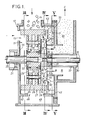
- Both forms of the pulverising machine comprises a housing 10 which defines a chamber 11, and is provided with a main air inlet 12, a secondary air inlet 13, a material inlet 14 and an outlet 15.
- a pulveriser rotor 16 Within the chamber 11 are a pulveriser rotor 16, guide means 17 and a rotary classifier 18.
- the chamber is substantially cylindrical about an axis 19 of a rotor drive shaft 20 which is mounted on bearings 21 so as to project into the chamber through one side wall of the casing.
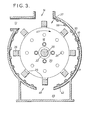
- the pulveriser rotor 16 comprises a hub 22 carrying a pair of parallel circular side plates 23 which support a circular array of bearing pins 24, each of which carries a swingable pulveriser member 25 having an outer portion 26 which projects radially from the periphery of the rotor so as to be disposed in an annular reducing zone 27 of the chamber, which zone 27 is indicated in broken lines in Figure 2.
- Each outer portion 26 has an extension 28 which projects from one side of the rotor 16, in a direction parallel to the axis, across the periphery of a classifier zone 29 of the chamber, which zone 29 is approximately cylindrical as indicated in broken lines in Figure 2.
- the rotary classifier 18 is disposed within the classifier zone 29 (indicated in broken lines in Figure 2), so as to be closely adjacent said one side of the rotor 16, and is carried by a second shaft 30, co-axial with said axis 19, which shaft 30 is carried by bearings 31 carried by a support 32 which projects within the outlet 15 to adjacent the rotary classifier.
- the housing 10 includes an annular wall 40 co-axial with the axis, which wall 40 surrounds the outlet and extends into the chamber to terminate at one side of the classifier zone.
- the wall 40 also serves an inner boundary of an annular conveyor zone 41 indicated in broken lines in Figure 2, which zone 41 extends outwards to a peripheral wall 42 of the housing so as to be disposed between a second side wall 43 of the casing and adjacent portions of the reducing and classifier zones. These adjacent portions comprise an outer portion 44 ( Figure 2) of the classifier zone and a final portion 45 ( Figure 2) of the reducing zone.
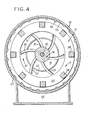
- the guide means 17 comprises a ring member 50 which is disc shaped, and several guide members 51, and is disposed across an intermediate portion of the conveyor zone 41, which intermediate portion is disposed between an inner portion 52 ( Figure 2) and an outer portion 53 ( Figure 2) of the conveyor zone.
- the ring member 50 serves as a partition between the intermediate portion and said adjacent portions 44 and 45.
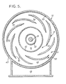
- the guide members 51 extend from said partition to the wall 43 and are shaped to define part spiral conveyor paths 54 Figures 5 and 8 which extend from said outer portion 53 to said inner portion 52.
- the extensions 28 lie in and are outwardly surrounded by the final portion 45, which final portion extends from a main portion 46 ( Figure 2) of the reducing zone, and the remainder of each outer portion 26 is disposed in and is outwardly surrounded by the main portion 46.
- the material inlet 14 is disposed at the top of the peripheral wall 42 and is radial to said axis so as to permit material, fed to the inlet by feed means (not shown), to fall towards the rotor through the main portion 46.
- the main air,inlet 12 is disposed adjacent to the material inlet 14, and ahead of the inlet 14 in the direction of rotation (arrow 47 in Figure 3) of the rotor, and is inclined so as to direct the flow of air in a direction tangential to the rotor and directly across the path of the material entering the reducing zone.
- the secondary air inlet 13 is disposed in said one side wall of the housing 10 so as to direct a flow of air through the reducing zone and across the rotor towards the conveyor zone.
- a bottom opening 48 is provided in the peripheral wall 42 to allow foreign bodies to fall into a trap 49 below the chamber.
- the trap has an external door or hatch, not shown.
- the walls of the chamber have a hard wearing internal skin 55 which is preferably ridged at least around the reducing zone to provide projections 56 transverse to the direction of rotation.
- the rotary classifier 18 comprises several vanes or blades 33, of channel shaped cross-section, which project from a hub 38 on the shaft 30.
- the vanes or blades 33 are curved to part spiral form so that the outer ends 34 lag the inner ends 35 in the direction of rotation of the classifier, which direction is indicated by the arrow 37 in Figure 4; and are located so that the walls 36 of the channels project in the direction of rotation.
- the rotary classifier 18 comprises short radially disposed vanes 133 which are carried by a circular plate 60 secured to the hub 38. These vanes 133 are radially short and terminate at a radius equal to that of the wall 40, and are braced by a ring plate 61 which overlaps the wall 40, which wall 40 is shortened to allow the axial length of the vanes 133 to be increased.
- the rotary classifier 18 incorporates rotary attenuator means 70.
- the outer ends 34 of the classifier vanes or blades 33 constitute the attenuator means 70 which is thus integrally incorporated in the rotary classifier: whereas in the form shown in Figure 6 the circular plate 60 carries radial arms 62 having outer ends 134 which constitute the attenuator means 70.
- the material is reduced by the pulveriser members 25 in the main portion 46, and a rotating flow of particulate material and air is produced, which flow moves progressively across the main portion 46 and across the final portion 45 - so as to enter the outer portion 44 whilst still rotating at a considerable velocity.
- the flow then enters the conveyor paths 54 and is carried by its momentum and the thrust of the air flow spirally inwards to the inner portion of the conveyor zone with minimal energy loss.
- the particle velocities are made more uniform, by mutual collisions, during transit through the paths.
- the flow then moves, whilst still rotating, back towards the rotor to enter the outer portion 44 of the classifier zone.
- the larger particles of the material will follow a return path indicated by arrow A outwards through the outer portion 44 and back into the final portion 45, due to the centrifugal forces acting on said particles; whereas the smaller particles (having a greater surface area to mass ratio) will be conveyed by the air flow inwards to an inner portion 57 of the classifier zone and then to the outlet 15, along a discharge path indicated by arrow B, so that said classifier zone serves as classifier means which utilises particle momentum to effect classification.
- the flow in the machine will create a pressure differential between the portions 53 and 52 tending to cause a flow from the final portion 45 to the portion 44 by-passing the conveyor zone: whereas the extensions 28 act collectively as an impeller to tend to draw a rotating current of air outwards, from the outer portion 44 of the classifier zone to the final portion 45 of the reducing zone 27.
- the nett result will, in most cases, be an appreciable outward movement of the rotating current of air.
- the impeller effect is reduced by the attenuator means if the latter rotates at a lesser speed than the rotational speed of the pulveriser rotor 16.
- the preferred range of speed of the shaft 30 is between 20% and 50% of the speed of the shaft 20.
- the impeller effect upon rotating current can also be reduced by providing radial fins 71 upon the partition as indicated in Figure 6, and by increasing the spacing between the extensions and the partition, at the expense of increasing the by-pass effect.
- the foregoing embodiment will provide the advantages, and avoid the disadvantages mentioned hereinbefore, and is adapted to be constructed in an economical manner, e.g. mainly from steel plate, so as to avoid expensive investment in castings and to enable the dimensions of the machines to be selected or varied to suit particular needs without requiring a range of casting patterns.
- the machine is constructed so as to facilitate repair and modification, e.g. the side 43 (together with the rotary classifier, outlet and a discharge duct 66) is detachable from the rest of the casing to provide access to the guide means, classifier and rotor; and the rotor is assembled so that one or both of the side plates 23 can be detached to release the pins 24 and members 25.
- the amount of further reduction can be reduced by reducing the projection of or the number of said extensions without reducing the amount of reduction of the material which takes place in the main portion 46 of the reducing zone.
- the machine does not "choke” i.e. become blocked, when fractionally overloaded or worked continuously at maximum capacity.
- the machine of the invention provides the further advantage that the energy of the flow in the machine is maintained to such a degree that it can drive the rotary classifier and/or the rotary attenuator if the latter is or are arranged to rotate more slowly than the pulveriser rotor, and power can be taken off the shaft 30.
- a drive motor 80 can be connected by a first belt and pulley transmission system 81 to the shaft 20 and by a second belt and pulley transmission system 82, preferably of variable speed form, to the shaft 30 to return power to the shaft 20 via the..motor.
- a lay shaft 84 may connect the transmission systems, as indicated in Figure 2.
- the guide means may be movable, may comprise adjustable guide members and means to adjust the guide members or means, may have guide members formed from steel plate, and each guide member may be constituted by a plurality of elements, and shaped members may be provided to smooth the path of the flow at the entrance to and the exit from the guide means.
- the rotor shaft may also carry the classifier for common rotation. Either or both of the air inlets may be provided.
- the or some of the pulveriser members may be fixed rigidly to the rotor.
- the size, shape, and form of the partition may be varied, e.g. to constrict the return path so that it narrows in the outwards direction, or to broaden the conveyor paths to compensate for any reduction in width, to give constant flow cross-sectional areas along the paths.
- the ring member may be omitted.
- the guide members may be flanged to provide an array of flanges between the extensions 28 and the conveyor paths, which array serves as a substantially continuous or interrupted partition.
- the air flow generated by the extensions 28, acting collectively as an impeller, can be adjusted by the attenuator means 70, thereby adjusting the flow through the conveyor zone 41, and in turn adjusting the speed of rotation of the flow emanating from the guide means 17.
- the centrifugal forces tending to reject oversize particles through the return path A to the final portion 45 may be altered and the threshold of particle size admitted to the outlet 15 adjusted independently of the rotary classifier or even in the absence of a rotary classifier.
- by-pass forces generated by the air flow through the machine are substantially equal to or somewhat greater than the impeller forces generated by the outer portion's extensions 28 and prevent a nett outward air movement through the return path, so as to minimise recycling of very small particles.
- the rotary attenuator may be mounted on a shaft concentric with the rotary classifier shaft for independent rotation.
- the classifier or attenuator may be driven by a shaft passing through the rotor shaft.
- the apparatus may be supplied with gas, gaseous medium, or a mixture thereof with air instead of an air supply.
- the air may be supplied under pressure, or the flow may be drawn from the duct 66 to induce the flow into the air inlet.
Landscapes
- Engineering & Computer Science (AREA)
- Food Science & Technology (AREA)
- Liquid Crystal Substances (AREA)
- Disintegrating Or Milling (AREA)
- Combined Means For Separation Of Solids (AREA)
- Crushing And Grinding (AREA)
- Crushing And Pulverization Processes (AREA)
Priority Applications (1)
| Application Number | Priority Date | Filing Date | Title |
|---|---|---|---|
| AT81304931T ATE25010T1 (de) | 1980-11-01 | 1981-10-21 | Zerkleinerungsmaschinen. |
Applications Claiming Priority (2)
| Application Number | Priority Date | Filing Date | Title |
|---|---|---|---|
| GB8035214 | 1980-11-01 | ||
| GB8035214 | 1980-11-01 |
Publications (3)
| Publication Number | Publication Date |
|---|---|
| EP0051389A2 true EP0051389A2 (de) | 1982-05-12 |
| EP0051389A3 EP0051389A3 (en) | 1983-02-16 |
| EP0051389B1 EP0051389B1 (de) | 1987-01-21 |
Family
ID=10517043
Family Applications (1)
| Application Number | Title | Priority Date | Filing Date |
|---|---|---|---|
| EP81304931A Expired EP0051389B1 (de) | 1980-11-01 | 1981-10-21 | Zerkleinerungsmaschinen |
Country Status (9)
| Country | Link |
|---|---|
| US (1) | US4479613A (de) |
| EP (1) | EP0051389B1 (de) |
| AT (1) | ATE25010T1 (de) |
| AU (1) | AU540390B2 (de) |
| CA (1) | CA1183112A (de) |
| DE (1) | DE3175844D1 (de) |
| GB (1) | GB2086261B (de) |
| NZ (1) | NZ198677A (de) |
| ZA (1) | ZA817365B (de) |
Cited By (1)
| Publication number | Priority date | Publication date | Assignee | Title |
|---|---|---|---|---|
| RU2153935C2 (ru) * | 1994-07-14 | 2000-08-10 | Бюлер Аг | Способ ударно-отражательного размола и ударно-отражательная мельница для его осуществления |
Families Citing this family (7)
| Publication number | Priority date | Publication date | Assignee | Title |
|---|---|---|---|---|
| GB2149688A (en) * | 1983-11-18 | 1985-06-19 | Geoffrey Thomas King | Hammer mill |
| US5083713A (en) * | 1989-04-10 | 1992-01-28 | Canon Kabushiki Kaisha | Process for disintegrating silica fine powder |
| AU651864B2 (en) * | 1991-02-15 | 1994-08-04 | Ronald Frederick Bourne | Treatment of particulate material |
| CH690709A5 (de) | 1995-09-25 | 2000-12-29 | Buehler Ag | Verfahren zur Prallvermahlung und Prallmühle. |
| JP3884826B2 (ja) * | 1996-07-30 | 2007-02-21 | キヤノン株式会社 | 固体粒子の表面の処理装置、固体粒子の表面の処理方法及びトナーの製造方法 |
| US8714467B2 (en) | 2010-01-29 | 2014-05-06 | Scott Equipment Company | Dryer/grinder |
| DE102013217164A1 (de) * | 2013-08-28 | 2015-03-05 | Panel Board Holding Bv | Zerkleinerungsvorrichtung |
Family Cites Families (5)
| Publication number | Priority date | Publication date | Assignee | Title |
|---|---|---|---|---|
| CA857861A (en) * | 1970-12-08 | G. Cheyne Donald | Rotary milling machines | |
| US3490704A (en) * | 1966-08-09 | 1970-01-20 | Asbestos Grading Equipment Co | Mills for the comminution of raw material |
| BE758817A (fr) * | 1969-11-12 | 1971-04-16 | Herbert Ltd A | Machines pour pulverisations |
| JPS5333783B2 (de) * | 1973-09-18 | 1978-09-16 | ||
| GB2061762B (en) * | 1979-10-30 | 1983-03-30 | British Rema Mfg Co Ltd | Pulverizing and classifying mill |
-
1981
- 1981-10-19 NZ NZ198677A patent/NZ198677A/en unknown
- 1981-10-21 AU AU76682/81A patent/AU540390B2/en not_active Ceased
- 1981-10-21 AT AT81304931T patent/ATE25010T1/de not_active IP Right Cessation
- 1981-10-21 DE DE8181304931T patent/DE3175844D1/de not_active Expired
- 1981-10-21 GB GB8131735A patent/GB2086261B/en not_active Expired
- 1981-10-21 EP EP81304931A patent/EP0051389B1/de not_active Expired
- 1981-10-23 ZA ZA817365A patent/ZA817365B/xx unknown
- 1981-10-27 CA CA000388799A patent/CA1183112A/en not_active Expired
- 1981-11-04 US US06/318,291 patent/US4479613A/en not_active Expired - Fee Related
Cited By (1)
| Publication number | Priority date | Publication date | Assignee | Title |
|---|---|---|---|---|
| RU2153935C2 (ru) * | 1994-07-14 | 2000-08-10 | Бюлер Аг | Способ ударно-отражательного размола и ударно-отражательная мельница для его осуществления |
Also Published As
| Publication number | Publication date |
|---|---|
| DE3175844D1 (en) | 1987-02-26 |
| ZA817365B (en) | 1982-10-27 |
| EP0051389B1 (de) | 1987-01-21 |
| GB2086261A (en) | 1982-05-12 |
| EP0051389A3 (en) | 1983-02-16 |
| CA1183112A (en) | 1985-02-26 |
| AU7668281A (en) | 1982-05-13 |
| ATE25010T1 (de) | 1987-02-15 |
| GB2086261B (en) | 1984-07-18 |
| US4479613A (en) | 1984-10-30 |
| NZ198677A (en) | 1985-11-08 |
| AU540390B2 (en) | 1984-11-15 |
Similar Documents
| Publication | Publication Date | Title |
|---|---|---|
| US4562972A (en) | Micropulverizer | |
| US4747550A (en) | Grinding mill with multiple milling sections | |
| US5269471A (en) | Pulverizer | |
| JPS59142877A (ja) | 空気分級機 | |
| US4479613A (en) | Pulverizing machines | |
| US2753996A (en) | Flow separators | |
| US2963230A (en) | Dry material pulverizer with integral classifier | |
| US5419499A (en) | Treatment of particulate material | |
| CA1038842A (en) | Crushing apparatus having centrifugal classifier | |
| US3372805A (en) | Fine particle classifier | |
| US2762572A (en) | Apparatus for disintegrating and classifying dry materials | |
| US2988220A (en) | Turbo-classifier | |
| RU2728628C1 (ru) | Центробежный классификатор со специальным рабочим колесом | |
| US2552596A (en) | Combined hammer mill crushing and oversize particle separating apparatus | |
| JPH10118571A (ja) | 鉛直軸式の空気分級機 | |
| US2414361A (en) | Impact mill with centrifugal separation | |
| US5263855A (en) | Low pressure drop rotating vertical vane inlet passage for coal pulverizer | |
| SU938236A1 (ru) | Дезинтегратор-сепаратор | |
| JPH06343887A (ja) | 石炭粉砕機用の改善された低圧力降下回転ベーン入口通路 | |
| US5190227A (en) | Beater mill with integrated centrifugal classifier | |
| US6935510B2 (en) | Air separator | |
| US1882390A (en) | Centrifugal machine | |
| US4435085A (en) | Mixer for use in pulp processes | |
| JP2000343040A (ja) | 遠心選別機 | |
| US2717741A (en) | Horizontal apparatus and method for disintegrating and classifying dry materials |
Legal Events
| Date | Code | Title | Description |
|---|---|---|---|
| PUAI | Public reference made under article 153(3) epc to a published international application that has entered the european phase |
Free format text: ORIGINAL CODE: 0009012 |
|
| AK | Designated contracting states |
Designated state(s): AT BE CH DE FR IT LU NL SE |
|
| PUAL | Search report despatched |
Free format text: ORIGINAL CODE: 0009013 |
|
| AK | Designated contracting states |
Designated state(s): AT BE CH DE FR IT LI LU NL SE |
|
| 17P | Request for examination filed |
Effective date: 19830321 |
|
| GRAA | (expected) grant |
Free format text: ORIGINAL CODE: 0009210 |
|
| AK | Designated contracting states |
Kind code of ref document: B1 Designated state(s): AT BE CH DE FR IT LI LU NL SE |
|
| PG25 | Lapsed in a contracting state [announced via postgrant information from national office to epo] |
Ref country code: NL Effective date: 19870121 Ref country code: LI Effective date: 19870121 Ref country code: IT Free format text: LAPSE BECAUSE OF FAILURE TO SUBMIT A TRANSLATION OF THE DESCRIPTION OR TO PAY THE FEE WITHIN THE PRESCRIBED TIME-LIMIT;WARNING: LAPSES OF ITALIAN PATENTS WITH EFFECTIVE DATE BEFORE 2007 MAY HAVE OCCURRED AT ANY TIME BEFORE 2007. THE CORRECT EFFECTIVE DATE MAY BE DIFFERENT FROM THE ONE RECORDED. Effective date: 19870121 Ref country code: CH Effective date: 19870121 Ref country code: AT Effective date: 19870121 |
|
| REF | Corresponds to: |
Ref document number: 25010 Country of ref document: AT Date of ref document: 19870215 Kind code of ref document: T |
|
| PG25 | Lapsed in a contracting state [announced via postgrant information from national office to epo] |
Ref country code: SE Effective date: 19870131 |
|
| REF | Corresponds to: |
Ref document number: 3175844 Country of ref document: DE Date of ref document: 19870226 |
|
| REG | Reference to a national code |
Ref country code: CH Ref legal event code: PL |
|
| NLV1 | Nl: lapsed or annulled due to failure to fulfill the requirements of art. 29p and 29m of the patents act | ||
| PG25 | Lapsed in a contracting state [announced via postgrant information from national office to epo] |
Ref country code: LU Free format text: LAPSE BECAUSE OF NON-PAYMENT OF DUE FEES Effective date: 19871031 |
|
| PLBE | No opposition filed within time limit |
Free format text: ORIGINAL CODE: 0009261 |
|
| STAA | Information on the status of an ep patent application or granted ep patent |
Free format text: STATUS: NO OPPOSITION FILED WITHIN TIME LIMIT |
|
| 26N | No opposition filed | ||
| PGFP | Annual fee paid to national office [announced via postgrant information from national office to epo] |
Ref country code: BE Payment date: 19901211 Year of fee payment: 10 |
|
| PG25 | Lapsed in a contracting state [announced via postgrant information from national office to epo] |
Ref country code: BE Effective date: 19911031 |
|
| BERE | Be: lapsed |
Owner name: SARDON INTERNATIONAL LTD Effective date: 19911031 |
|
| PGFP | Annual fee paid to national office [announced via postgrant information from national office to epo] |
Ref country code: FR Payment date: 19921030 Year of fee payment: 12 |
|
| PGFP | Annual fee paid to national office [announced via postgrant information from national office to epo] |
Ref country code: DE Payment date: 19921217 Year of fee payment: 12 |
|
| PG25 | Lapsed in a contracting state [announced via postgrant information from national office to epo] |
Ref country code: FR Effective date: 19940630 |
|
| PG25 | Lapsed in a contracting state [announced via postgrant information from national office to epo] |
Ref country code: DE Effective date: 19940701 |
|
| REG | Reference to a national code |
Ref country code: FR Ref legal event code: ST |