EP0051011B1 - Canne pyrométrique - Google Patents
Canne pyrométrique Download PDFInfo
- Publication number
- EP0051011B1 EP0051011B1 EP81401590A EP81401590A EP0051011B1 EP 0051011 B1 EP0051011 B1 EP 0051011B1 EP 81401590 A EP81401590 A EP 81401590A EP 81401590 A EP81401590 A EP 81401590A EP 0051011 B1 EP0051011 B1 EP 0051011B1
- Authority
- EP
- European Patent Office
- Prior art keywords
- pyrometer
- rod
- metal
- tip
- spacer
- Prior art date
- Legal status (The legal status is an assumption and is not a legal conclusion. Google has not performed a legal analysis and makes no representation as to the accuracy of the status listed.)
- Expired
Links
- 229910052751 metal Inorganic materials 0.000 claims description 12
- 239000002184 metal Substances 0.000 claims description 12
- 239000011521 glass Substances 0.000 claims description 10
- 239000011819 refractory material Substances 0.000 claims description 9
- 125000006850 spacer group Chemical group 0.000 claims description 9
- BASFCYQUMIYNBI-UHFFFAOYSA-N platinum Chemical compound [Pt] BASFCYQUMIYNBI-UHFFFAOYSA-N 0.000 claims description 6
- PNEYBMLMFCGWSK-UHFFFAOYSA-N aluminium oxide Inorganic materials [O-2].[O-2].[O-2].[Al+3].[Al+3] PNEYBMLMFCGWSK-UHFFFAOYSA-N 0.000 claims description 4
- 229910052851 sillimanite Inorganic materials 0.000 claims description 4
- 229910001260 Pt alloy Inorganic materials 0.000 claims description 3
- 229910052697 platinum Inorganic materials 0.000 claims description 3
- 239000004568 cement Substances 0.000 claims description 2
- 230000004927 fusion Effects 0.000 claims description 2
- 229910001092 metal group alloy Inorganic materials 0.000 claims description 2
- 229910052703 rhodium Inorganic materials 0.000 claims description 2
- 239000010948 rhodium Substances 0.000 claims description 2
- MHOVAHRLVXNVSD-UHFFFAOYSA-N rhodium atom Chemical compound [Rh] MHOVAHRLVXNVSD-UHFFFAOYSA-N 0.000 claims description 2
- 239000006060 molten glass Substances 0.000 description 7
- VYPSYNLAJGMNEJ-UHFFFAOYSA-N Silicium dioxide Chemical compound O=[Si]=O VYPSYNLAJGMNEJ-UHFFFAOYSA-N 0.000 description 2
- CDBYLPFSWZWCQE-UHFFFAOYSA-L Sodium Carbonate Chemical compound [Na+].[Na+].[O-]C([O-])=O CDBYLPFSWZWCQE-UHFFFAOYSA-L 0.000 description 2
- 239000000919 ceramic Substances 0.000 description 2
- 238000005816 glass manufacturing process Methods 0.000 description 2
- 238000005259 measurement Methods 0.000 description 2
- PXXKQOPKNFECSZ-UHFFFAOYSA-N platinum rhodium Chemical compound [Rh].[Pt] PXXKQOPKNFECSZ-UHFFFAOYSA-N 0.000 description 2
- OKTJSMMVPCPJKN-UHFFFAOYSA-N Carbon Chemical compound [C] OKTJSMMVPCPJKN-UHFFFAOYSA-N 0.000 description 1
- RYGMFSIKBFXOCR-UHFFFAOYSA-N Copper Chemical compound [Cu] RYGMFSIKBFXOCR-UHFFFAOYSA-N 0.000 description 1
- 206010013647 Drowning Diseases 0.000 description 1
- ZOKXTWBITQBERF-UHFFFAOYSA-N Molybdenum Chemical compound [Mo] ZOKXTWBITQBERF-UHFFFAOYSA-N 0.000 description 1
- 241001639412 Verres Species 0.000 description 1
- 239000000470 constituent Substances 0.000 description 1
- 229910052802 copper Inorganic materials 0.000 description 1
- 239000010949 copper Substances 0.000 description 1
- 230000007797 corrosion Effects 0.000 description 1
- 238000005260 corrosion Methods 0.000 description 1
- 238000004519 manufacturing process Methods 0.000 description 1
- 239000000203 mixture Substances 0.000 description 1
- 229910052750 molybdenum Inorganic materials 0.000 description 1
- 239000011733 molybdenum Substances 0.000 description 1
- 239000000843 powder Substances 0.000 description 1
- 239000003870 refractory metal Substances 0.000 description 1
- 239000000377 silicon dioxide Substances 0.000 description 1
- 229910000029 sodium carbonate Inorganic materials 0.000 description 1
- 235000017550 sodium carbonate Nutrition 0.000 description 1
- 239000010935 stainless steel Substances 0.000 description 1
- 229910001220 stainless steel Inorganic materials 0.000 description 1
Images
Classifications
-
- G—PHYSICS
- G01—MEASURING; TESTING
- G01K—MEASURING TEMPERATURE; MEASURING QUANTITY OF HEAT; THERMALLY-SENSITIVE ELEMENTS NOT OTHERWISE PROVIDED FOR
- G01K1/00—Details of thermometers not specially adapted for particular types of thermometer
- G01K1/08—Protective devices, e.g. casings
-
- G—PHYSICS
- G01—MEASURING; TESTING
- G01K—MEASURING TEMPERATURE; MEASURING QUANTITY OF HEAT; THERMALLY-SENSITIVE ELEMENTS NOT OTHERWISE PROVIDED FOR
- G01K1/00—Details of thermometers not specially adapted for particular types of thermometer
- G01K1/14—Supports; Fastening devices; Arrangements for mounting thermometers in particular locations
Definitions
- the invention relates to a pyrometric rod as described in the preamble of claim 1.
- the known pyrometric rods generally consist of a body of refractory material containing a thermocouple, the body being protected, over its entire length, from the aggressive environment constituted by the molten glass and the atmosphere overhanging the bath, by a long sheath in ceramic or refractory metal, in practice platinum or a platinum alloy.
- this sheath is fixed in a relatively cold zone which means that it has to be given a length of the order of 60 cm to 1 m and is therefore very expensive.
- thermometric device for a vacuum oven.
- This device comprises a ceramic oxide sheath surrounded in its part. lower by another molybdenum sheath and in its upper part by a copper tube.
- the invention provides a pyrometric rod for measuring the temperatures of molten glass having almost unlimited corrosion resistance over time while being particularly economical.
- the pyrometer according to the invention includes metal parts, at least one thermocouple for measuring the tem - perature of the molten glass, a refractory material containing the rod or the torque (s) thermoelectric (s) and provided with a tip of short length, made of metal or a metal alloy chemically and mechanically resistant to the action of glass and the atmosphere overhanging the bath, this pyrometric rod being characterized in that said metal tip is mounted directly on said rod and is surmounted by a spacer made of refractory material thermally insulating it from the other metal parts belonging to the pyrometric rod.
- the platinum or platinum alloy tip is surmounted by a spacer made of refractory material such as a sillimanite tube, this spacer being pushed by an elastic return means. such as a spring, to be applied to the bottom of a tubular support forming a downward well in the immediate vicinity of the glass, said support being in refractory, such as sillimanite and belonging to the pyrometric rod or to an intermediate piece serving for the operation of the cane.
- a spacer made of refractory material such as a sillimanite tube, this spacer being pushed by an elastic return means. such as a spring, to be applied to the bottom of a tubular support forming a downward well in the immediate vicinity of the glass, said support being in refractory, such as sillimanite and belonging to the pyrometric rod or to an intermediate piece serving for the operation of the cane.
- the rod according to the invention forms a rigid assembly which is easy to assemble and disassemble as a block since it is free of particular fixing means such as pins or clamps.
- the pyrometric rod comprises several thermoelectric couples associated so that their hot welds are located at different levels; it thus makes it possible to simultaneously obtain several temperature readings stepped over the entire height of the bath.
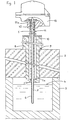
- FIG. 1 shows the pyrometric rod 1 passing through the vault of refractory material 2 of a channel delimited by a refractory block 3 within which circulates molten glass, the level of which is shown in 4.
- the pyrometric rod is formed of a rod formed of a blind tube 5 of refractory material such as alumina containing one or more thermocouples as described below.
- the lower end of the rod is protected by a tip 6 made of 10% rhodium platinum, chemically and mechanically resistant to the actions of molten glass and the atmosphere overhanging the bath.
- the rod 5 is inserted with gentle friction into the end piece 6.
- This short end piece (this length being a function of the height of the glass generally about twenty cm long for a rod measuring the temperatures in a channel at the exit from the glass making oven) in the form of a thimble, has a collar 7 which serves as a positioning stop.
- the rod 5 and its end piece 6 pass through an orifice formed at the base of a refractory rectified tubular support 8, belonging to the rod.
- This support 8 housed in an opening made in the vault 2, bears on the upper face of this vault by means of a shoulder 9. It forms a well, the bottom 8a of which is very close, of the order of a few centimeters from the glass surface.
- the rod 5 and the end-piece 6 are held in place by a spacer tube 10 made of refractory material, the upper part of which is inserted into an extension 11 consisting of a metal tube, made of stainless steel for example, and blocked by a spring 12 in press on its cover 11a. Under the action of this spring, the lower end of the spacer tube presses the collar 7 of the end piece 6 onto the rectified bottom of the well of the support 8.
- the upper part of the rod is formed by the measuring head 13. This gives a rigid assembly, assembled by simple fitting without other fixing means such as pins or clamps, and easy to assemble and disassemble.
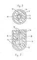
- FIGS 2 and 3 show the arrangement of the constituent elements of the pyrometric rod and in particular the location of the thermocouples.
- the various hot welds 14 exit at the bottom of the refractory capillary sheaths 15, isolating the wires from the thermocouples.
- These capillary sheaths 15, generally made of alumina, are joined together so that the hot welds 14 are spaced along the longitudinal axis of the pyrometric rod and their spacing remains constant.
- thermocouples thus assembled are introduced into the rod 5.
- the rod is finally threaded into the metal tip 6 and placed in the support 8 for its placement in the oven or the channel.
- An example of a pyrometric rod according to the invention comprises three thermocouples in rhodium platinum at 30% and 6% rhodium, the wires of which are isolated by alumina capillaries supplied by the company DEGUSSA.
- the three hot welds are respectively placed just below the free surface of the glass bath, in the middle of the glass stream and near the floor.
- the metal end piece has a thickness of the order of a millimeter while the refractory rod has a thickness of the order of 2 millimeters.
- This structure provides sufficient rigidity to avoid deformations likely to be caused by rapid flow of the glass.
Landscapes
- Physics & Mathematics (AREA)
- General Physics & Mathematics (AREA)
- Measuring Temperature Or Quantity Of Heat (AREA)
Applications Claiming Priority (2)
| Application Number | Priority Date | Filing Date | Title |
|---|---|---|---|
| FR8021903A FR2492096A1 (fr) | 1980-10-14 | 1980-10-14 | Canne pyrometrique |
| FR8021903 | 1980-10-14 |
Publications (2)
| Publication Number | Publication Date |
|---|---|
| EP0051011A1 EP0051011A1 (fr) | 1982-05-05 |
| EP0051011B1 true EP0051011B1 (fr) | 1985-08-07 |
Family
ID=9246844
Family Applications (1)
| Application Number | Title | Priority Date | Filing Date |
|---|---|---|---|
| EP81401590A Expired EP0051011B1 (fr) | 1980-10-14 | 1981-10-14 | Canne pyrométrique |
Country Status (6)
| Country | Link |
|---|---|
| US (1) | US4428686A (enExample) |
| EP (1) | EP0051011B1 (enExample) |
| CA (1) | CA1192667A (enExample) |
| DE (1) | DE3171716D1 (enExample) |
| ES (1) | ES506205A0 (enExample) |
| FR (1) | FR2492096A1 (enExample) |
Families Citing this family (20)
| Publication number | Priority date | Publication date | Assignee | Title |
|---|---|---|---|---|
| US4603980A (en) * | 1984-02-03 | 1986-08-05 | Owens-Corning Fiberglas Corporation | Methods of measuring temperature and electrical resistivity in a molten glass stream |
| US4724428A (en) * | 1986-07-07 | 1988-02-09 | Emhart Industries, Inc. | Thermocouple jacket monitor |
| US4746344A (en) * | 1987-02-02 | 1988-05-24 | Ppg Industries, Inc. | Fiber forming bushing and method for providing |
| DE4016404A1 (de) * | 1990-05-22 | 1991-11-28 | Koertvelyessy Laszlo | Fluessigstahl-thermoelement mit linearer drift |
| FR2676812B1 (fr) * | 1991-05-24 | 1994-09-02 | Thermo Controle | Dispositif pour mesurer la temperature dans une ambiance explosible. |
| DE9109308U1 (de) * | 1991-07-27 | 1992-11-26 | Hoechst Ag, 65929 Frankfurt | Temperaturmeßvorrichtung |
| US5775807A (en) * | 1996-02-26 | 1998-07-07 | Gay Engineering & Sales Co., Inc. | Introducing a plurality of temperature measuring devices into a pressure vessel |
| US6701751B2 (en) * | 2001-06-14 | 2004-03-09 | Avacon, S.A. | Glass melting furnace |
| US8109670B2 (en) * | 2003-03-31 | 2012-02-07 | Saudi Arabian Oil Company | Measurement of molten sulfur level in receptacles |
| US7347290B2 (en) * | 2004-06-15 | 2008-03-25 | Smith International, Inc. | Multi-part energizer for mechanical seal assembly |
| DE102004032561B3 (de) * | 2004-07-05 | 2006-02-09 | Heraeus Electro-Nite International N.V. | Behälter für Metallschmelze sowie Verwendung des Behälters |
| EP2386843B1 (de) * | 2010-05-11 | 2016-08-03 | Innovatherm Prof. Dr. Leisenberg GmbH & Co. KG | Thermoelement |
| DE102011012175A1 (de) * | 2011-02-23 | 2012-08-23 | Heraeus Electro-Nite International N.V. | Sensoranordnung zur Messung von Parametern in Schmelzen |
| CN102636277A (zh) * | 2012-04-10 | 2012-08-15 | 巨石集团有限公司 | 一种用于玻纤通路玻璃液测温的新型热电偶及其使用方法 |
| US20140353864A1 (en) * | 2013-05-28 | 2014-12-04 | Chester Grochoski | System, method and apparatus for controlling ground or concrete temperature |
| US9523650B2 (en) * | 2013-09-06 | 2016-12-20 | Conax Technologies Llc | Spring loaded exhaust gas temperature sensor assembly |
| US20170322091A1 (en) * | 2016-05-04 | 2017-11-09 | Gas Turbine Specialty Parts LLC | Open air thermowell |
| US10677658B2 (en) * | 2016-09-06 | 2020-06-09 | Hamilton Sundstrand Corporation | Retaining systems and methods |
| JP7021229B2 (ja) * | 2016-12-30 | 2022-02-16 | ローズマウント インコーポレイテッド | 調節可能なばねが装備された温度センサ用アダプタ |
| US11366023B2 (en) * | 2019-07-02 | 2022-06-21 | Gas Turbine Specialty Parts LLC | Multi-piece thermowell |
Family Cites Families (13)
| Publication number | Priority date | Publication date | Assignee | Title |
|---|---|---|---|---|
| DE1133914B (de) * | 1953-12-18 | 1962-07-26 | Koppers Gmbh Heinrich | Verfahren zur Herstellung einer aeusseren Mantelschicht aus Siliziumkarbid und einer Tonbindung auf ein keramisches Schutzrohr fuer thermoelektrische Temperaturfuehler |
| DE959857C (de) * | 1954-06-16 | 1957-03-14 | Thyssen Huette Ag | Schutzrohr fuer Thermoelemente der Platingruppe |
| SU147817A1 (ru) | 1961-03-13 | 1961-11-30 | И.Г. Хаврунюк | Газонепроницаемый трехслойный защитный наконечник термопары |
| FR1327138A (fr) * | 1962-04-02 | 1963-05-17 | Dumay Pere & Fils | Perfectionnements aux appareils de mesure de hautes températures dénommés cannes ou sondes pyrométriques |
| US3329534A (en) | 1963-02-14 | 1967-07-04 | Engelhard Ind Inc | Thermocouple with platinum group metal inner sheath |
| FR1423845A (fr) * | 1964-11-23 | 1966-01-07 | Creusot Forges Ateliers | Canne pyrométrique pour la mesure continue de la température de la fonte liquide |
| GB1164431A (en) | 1966-01-18 | 1969-09-17 | Pilkington Brothers Ltd | Improvements relating to the Protection of Instruments Intended for Use at High Temperatures |
| CH452224A (de) * | 1967-03-14 | 1968-05-31 | Balzers Patent Beteilig Ag | Temperatur- und Messeinrichtung für Vakuumöfen |
| US3923552A (en) * | 1972-12-21 | 1975-12-02 | Ppg Industries Inc | Hermetically sealed thermocouple assembly |
| DE2411995A1 (de) * | 1973-04-20 | 1974-10-31 | Plansee Metallwerk | Vorrichtung zur temperaturmessung mittels thermoelementen |
| FR2333228A1 (fr) * | 1975-11-26 | 1977-06-24 | Controle Measure Regulation | Un dispositif de protection contre les vibrations des thermo-elements a resistance ou thermistance |
| CH641211A5 (en) | 1978-09-08 | 1984-02-15 | Alusuisse | Appliance for the continuous measurement of the temperature of electrolyte melts |
| US4243402A (en) | 1978-09-13 | 1981-01-06 | Ppg Industries, Inc. | Apparatus for measuring temperatures in molten metal |
-
1980
- 1980-10-14 FR FR8021903A patent/FR2492096A1/fr active Granted
-
1981
- 1981-10-07 US US06/309,257 patent/US4428686A/en not_active Expired - Lifetime
- 1981-10-13 ES ES506205A patent/ES506205A0/es active Granted
- 1981-10-13 CA CA000387747A patent/CA1192667A/fr not_active Expired
- 1981-10-14 EP EP81401590A patent/EP0051011B1/fr not_active Expired
- 1981-10-14 DE DE8181401590T patent/DE3171716D1/de not_active Expired
Also Published As
| Publication number | Publication date |
|---|---|
| ES8304306A1 (es) | 1982-09-01 |
| FR2492096B1 (enExample) | 1983-04-15 |
| CA1192667A (fr) | 1985-08-27 |
| DE3171716D1 (de) | 1985-09-12 |
| FR2492096A1 (fr) | 1982-04-16 |
| ES506205A0 (es) | 1982-09-01 |
| EP0051011A1 (fr) | 1982-05-05 |
| US4428686A (en) | 1984-01-31 |
Similar Documents
| Publication | Publication Date | Title |
|---|---|---|
| EP0051011B1 (fr) | Canne pyrométrique | |
| KR101010181B1 (ko) | 내연기관의 배기가스 시스템에 사용되는 저항 온도계용온도 센서 | |
| EP0454846B1 (en) | Thermocouple-type temperature sensor and method of measuring temperature of molten steel | |
| FR2783917A1 (fr) | Capteur de temperature | |
| KR20070086868A (ko) | 용융 구리 주조용 라운더 | |
| AU2011202054A1 (en) | Sensor arrangement for temperature measurement, and method for the measurement | |
| FR2465691A1 (fr) | Ensemble destine au montage d'une electrode sur le bati d'un avant-corps d'un four de fusion de verre | |
| US4259866A (en) | Pyrometer assembly having a heated viewing tube | |
| JP3158839B2 (ja) | 溶融金属の温度測定装置および温度測定方法 | |
| US4919543A (en) | Molten metal temperature probe | |
| KR19990082256A (ko) | 용융용기에서 용융온도를 측정하기 위한 방법 및 장치 | |
| US4556202A (en) | Under-heater type furnace | |
| HUT54737A (en) | Fire-resisting gas-permeable injecting stone | |
| US3954507A (en) | Thermocouples used for measuring temperatures | |
| JPH0567893B2 (enExample) | ||
| KR20190017966A (ko) | 열전대 | |
| US3201277A (en) | Immersion thermocouple | |
| JPH09113372A (ja) | 多点測温素子 | |
| FR2608884A1 (fr) | Dispositif de chauffage par resistance electrique a double isolement | |
| JP3952132B2 (ja) | 金属溶湯用熱電対 | |
| JP3550915B2 (ja) | 高温測温用セラミック熱電対 | |
| AU2005202566A1 (en) | Guide system for signal lines, device for measuring temperatures and/or concentrations and use | |
| JP3645439B2 (ja) | 熱電対装置 | |
| US3451863A (en) | Single-cast immersion thermocouple for continuous measurement of molten metal temperatures | |
| JPH0339701Y2 (enExample) |
Legal Events
| Date | Code | Title | Description |
|---|---|---|---|
| PUAI | Public reference made under article 153(3) epc to a published international application that has entered the european phase |
Free format text: ORIGINAL CODE: 0009012 |
|
| AK | Designated contracting states |
Designated state(s): CH DE FR GB IT NL SE |
|
| 17P | Request for examination filed |
Effective date: 19821011 |
|
| ITF | It: translation for a ep patent filed | ||
| GRAA | (expected) grant |
Free format text: ORIGINAL CODE: 0009210 |
|
| AK | Designated contracting states |
Designated state(s): CH DE FR GB IT LI NL SE |
|
| REF | Corresponds to: |
Ref document number: 3171716 Country of ref document: DE Date of ref document: 19850912 |
|
| REG | Reference to a national code |
Ref country code: CH Ref legal event code: PFA Free format text: SAINT-GOBAIN EMBALLAGE |
|
| PLBE | No opposition filed within time limit |
Free format text: ORIGINAL CODE: 0009261 |
|
| STAA | Information on the status of an ep patent application or granted ep patent |
Free format text: STATUS: NO OPPOSITION FILED WITHIN TIME LIMIT |
|
| 26N | No opposition filed | ||
| ITTA | It: last paid annual fee | ||
| EAL | Se: european patent in force in sweden |
Ref document number: 81401590.5 |
|
| PGFP | Annual fee paid to national office [announced via postgrant information from national office to epo] |
Ref country code: SE Payment date: 20000914 Year of fee payment: 20 |
|
| PGFP | Annual fee paid to national office [announced via postgrant information from national office to epo] |
Ref country code: GB Payment date: 20001006 Year of fee payment: 20 |
|
| PGFP | Annual fee paid to national office [announced via postgrant information from national office to epo] |
Ref country code: FR Payment date: 20001011 Year of fee payment: 20 |
|
| PGFP | Annual fee paid to national office [announced via postgrant information from national office to epo] |
Ref country code: NL Payment date: 20001031 Year of fee payment: 20 |
|
| PGFP | Annual fee paid to national office [announced via postgrant information from national office to epo] |
Ref country code: DE Payment date: 20001115 Year of fee payment: 20 |
|
| PGFP | Annual fee paid to national office [announced via postgrant information from national office to epo] |
Ref country code: CH Payment date: 20010118 Year of fee payment: 20 |
|
| PG25 | Lapsed in a contracting state [announced via postgrant information from national office to epo] |
Ref country code: LI Free format text: LAPSE BECAUSE OF EXPIRATION OF PROTECTION Effective date: 20011013 Ref country code: GB Free format text: LAPSE BECAUSE OF EXPIRATION OF PROTECTION Effective date: 20011013 Ref country code: CH Free format text: LAPSE BECAUSE OF EXPIRATION OF PROTECTION Effective date: 20011013 |
|
| PG25 | Lapsed in a contracting state [announced via postgrant information from national office to epo] |
Ref country code: NL Free format text: LAPSE BECAUSE OF EXPIRATION OF PROTECTION Effective date: 20011014 |
|
| PG25 | Lapsed in a contracting state [announced via postgrant information from national office to epo] |
Ref country code: SE Free format text: THE PATENT HAS BEEN ANNULLED BY A DECISION OF A NATIONAL AUTHORITY Effective date: 20011030 |
|
| REG | Reference to a national code |
Ref country code: GB Ref legal event code: PE20 Effective date: 20011013 |
|
| REG | Reference to a national code |
Ref country code: CH Ref legal event code: PL |
|
| EUG | Se: european patent has lapsed |
Ref document number: 81401590.5 |
|
| NLV7 | Nl: ceased due to reaching the maximum lifetime of a patent |
Effective date: 20011014 |