EP0050107A2 - Sitting furniture - Google Patents
Sitting furniture Download PDFInfo
- Publication number
- EP0050107A2 EP0050107A2 EP81890162A EP81890162A EP0050107A2 EP 0050107 A2 EP0050107 A2 EP 0050107A2 EP 81890162 A EP81890162 A EP 81890162A EP 81890162 A EP81890162 A EP 81890162A EP 0050107 A2 EP0050107 A2 EP 0050107A2
- Authority
- EP
- European Patent Office
- Prior art keywords
- pull
- foot
- out part
- seating furniture
- backrest
- Prior art date
- Legal status (The legal status is an assumption and is not a legal conclusion. Google has not performed a legal analysis and makes no representation as to the accuracy of the status listed.)
- Granted
Links
Images

Classifications
-
- A—HUMAN NECESSITIES
- A47—FURNITURE; DOMESTIC ARTICLES OR APPLIANCES; COFFEE MILLS; SPICE MILLS; SUCTION CLEANERS IN GENERAL
- A47C—CHAIRS; SOFAS; BEDS
- A47C17/00—Sofas; Couches; Beds
- A47C17/04—Seating furniture, e.g. sofas, couches, settees, or the like, with movable parts changeable to beds; Chair beds
- A47C17/16—Seating furniture changeable to beds by tilting or pivoting the back-rest
- A47C17/20—Seating furniture changeable to beds by tilting or pivoting the back-rest thereby uncovering one or more auxiliary parts previously hidden
- A47C17/207—Seating furniture changeable to beds by tilting or pivoting the back-rest thereby uncovering one or more auxiliary parts previously hidden with seat cushion consisting of multiple superposed parts, at least one lower hidden part being used to form part of the bed surface
- A47C17/2076—Seating furniture changeable to beds by tilting or pivoting the back-rest thereby uncovering one or more auxiliary parts previously hidden with seat cushion consisting of multiple superposed parts, at least one lower hidden part being used to form part of the bed surface by lifting or tilting
-
- A—HUMAN NECESSITIES
- A47—FURNITURE; DOMESTIC ARTICLES OR APPLIANCES; COFFEE MILLS; SPICE MILLS; SUCTION CLEANERS IN GENERAL
- A47C—CHAIRS; SOFAS; BEDS
- A47C17/00—Sofas; Couches; Beds
- A47C17/04—Seating furniture, e.g. sofas, couches, settees, or the like, with movable parts changeable to beds; Chair beds
- A47C17/13—Seating furniture having non-movable backrest changeable to beds by increasing the available seat part, e.g. by drawing seat cushion forward
- A47C17/132—Seating furniture having non-movable backrest changeable to beds by increasing the available seat part, e.g. by drawing seat cushion forward with multiple seat cushions
- A47C17/134—Seating furniture having non-movable backrest changeable to beds by increasing the available seat part, e.g. by drawing seat cushion forward with multiple seat cushions by lifting or tilting
-
- A—HUMAN NECESSITIES
- A47—FURNITURE; DOMESTIC ARTICLES OR APPLIANCES; COFFEE MILLS; SPICE MILLS; SUCTION CLEANERS IN GENERAL
- A47C—CHAIRS; SOFAS; BEDS
- A47C17/00—Sofas; Couches; Beds
- A47C17/04—Seating furniture, e.g. sofas, couches, settees, or the like, with movable parts changeable to beds; Chair beds
- A47C17/16—Seating furniture changeable to beds by tilting or pivoting the back-rest
- A47C17/165—Seating furniture changeable to beds by tilting or pivoting the back-rest with forward tiltable back-rest, e.g. back cushion
-
- A—HUMAN NECESSITIES
- A47—FURNITURE; DOMESTIC ARTICLES OR APPLIANCES; COFFEE MILLS; SPICE MILLS; SUCTION CLEANERS IN GENERAL
- A47C—CHAIRS; SOFAS; BEDS
- A47C17/00—Sofas; Couches; Beds
- A47C17/04—Seating furniture, e.g. sofas, couches, settees, or the like, with movable parts changeable to beds; Chair beds
- A47C17/16—Seating furniture changeable to beds by tilting or pivoting the back-rest
- A47C17/20—Seating furniture changeable to beds by tilting or pivoting the back-rest thereby uncovering one or more auxiliary parts previously hidden
- A47C17/207—Seating furniture changeable to beds by tilting or pivoting the back-rest thereby uncovering one or more auxiliary parts previously hidden with seat cushion consisting of multiple superposed parts, at least one lower hidden part being used to form part of the bed surface
- A47C17/2073—Seating furniture changeable to beds by tilting or pivoting the back-rest thereby uncovering one or more auxiliary parts previously hidden with seat cushion consisting of multiple superposed parts, at least one lower hidden part being used to form part of the bed surface by sliding forward
-
- A—HUMAN NECESSITIES
- A47—FURNITURE; DOMESTIC ARTICLES OR APPLIANCES; COFFEE MILLS; SPICE MILLS; SUCTION CLEANERS IN GENERAL
- A47C—CHAIRS; SOFAS; BEDS
- A47C17/00—Sofas; Couches; Beds
- A47C17/04—Seating furniture, e.g. sofas, couches, settees, or the like, with movable parts changeable to beds; Chair beds
- A47C17/22—Seating furniture having non-movable back-rest changeable to beds with means for uncovering a previously hidden mattress or similar bed part
- A47C17/23—Seating furniture having non-movable back-rest changeable to beds with means for uncovering a previously hidden mattress or similar bed part the lying down bed surface partly consisting of one side of the seat
Definitions
- the invention relates to a piece of seating furniture which can be converted into a bed, the lying surface of which is formed by three cushion units, namely a head part, a middle part and a foot part.
- This seating furniture consists of a base part supporting a backrest, which is laterally provided with guide rails on which the rear end of a pull-out part is guided, the front end of which is provided with rollers.
- the known seating of this type was of a very complex design in that it had two pull-out parts which could be pulled out from a base and telescoped into one another, of which the inner or front pull-out part was formed in one piece with the foot part and the middle part, which when the two were in the inserted position Pull-out parts lay on the foot section, after the two pull-out parts had been pulled out they were swiveled by 180 ° and thus came to rest on the outer, rear pull-out part.
- this had the consequence that the lying height, which corresponds to the seat height of 42 cm for a normal bed, decreased considerably (about half), which was particularly uncomfortable for older and frail people.
- the aim of the invention is to eliminate the disadvantages mentioned and to create a piece of seating furniture of the type mentioned at the outset which has a lying height corresponding to the seat height and is simple and robust in its construction and inexpensive to manufacture and which also makes it possible with both the seat of the seating furniture and the middle part of the bed surface a hard and therefore largely to prevent wear of the fabric cover suspension.
- the pull-out part has the shape of a drawer, on the upper side of which the middle part is articulated as a cover, the foot part being pivoted and / or slidably mounted in the pull-out part.
- the foot part is articulated on the pull-out part opposite the middle part, the back parts of the foot part and the middle part closing off the cavity being in contact with one another when the furniture is used for sitting.
- the foot part is articulated on side arms, which in turn are pivotably mounted in the pull-out part, the foot part lying in the folded-up state with the padded side upward.
- a pivoting of the foot part by 180 ° is not necessary in this embodiment.
- the foot part can be displaceable on guides which are arranged so as to lead obliquely upwards within the pull-out part.
- Lifting the foot part out of the pull-out part is made considerably easier in one embodiment in which the foot part is fastened to a spring-loaded fitting arranged within the pull-out part and provided with parallelogram links, the web of which is pivotably mounted on the pull-out part.
- the backrest In the context of the invention it is possible to rigidly connect the backrest to the base part, in which case there is great freedom of movement in the design of the backrest.
- a loose cushion inserted into the pull-out part can be used as the head part.
- the backrest can be used as a head part.
- a particularly expedient embodiment of this type is characterized in that one end of a flexible strip of canvas, drillich or the like, is attached to the base part, the opposite end of which ver with the pull-out part is bound, the backrest can be placed as s head part on the flexible strip when the pull-out part is pulled out.
- the backrest can be pivotally connected to the base part simply by means of a fabric hinge. In such an embodiment, expensive fittings are saved on the one hand, and on the other hand a secure mounting of the back part lying on the flexible strip is achieved.
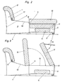
- FIG. 1 shows an embodiment of the piece of furniture in the position intended for sitting
- FIG. 2 this piece of furniture after the pull-out part has been pulled out
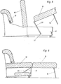
- FIG. 3 this piece of furniture after the middle part and the foot part have been folded up
- FIG. 4 the piece of furniture converted into a bed
- 5 shows a further embodiment in an intermediate position
- FIG. 6 shows the same piece of furniture in a rest position typical of all embodiments of the invention
- FIG. 7 shows another embodiment of the invention in an intermediate position
- FIG. 8 shows this embodiment in the lying position
- FIG. 9 a variant equipped with a jumping bracket in various intermediate positions.
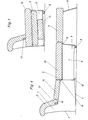
- the rear end 5 of a pull-out part 6 is guided on these guide rails 4.
- the front end 7 of the pull-out part 6 is provided with rollers 8.
- the back of the base part 1 is designated 1 '.
- the pull-out part 6 carries pivot axes 11, 12 at both ends of its upper side, which are at least approximately in the same horizontal plane and to which a middle part 10 and a foot part 9 are articulated.
- the middle part 10 which rests on the top of the pull-out part 6 in both positions of use of the seating furniture, is articulated on the pivot axis 11 adjacent to the rear side 1 'of the base part 1, while the foot part 9 is articulated on the pivot axis 12 removed from the rear side 1'.
- the pull-out part 6 has the shape of a drawer, the cavity of which is intended to receive the foot part 9 and a loosely inserted head part 14.
- the foot part 9 which is pivoted into the cavity of the drawer, and the middle part 10, which closes the cavity on its upper side, lie against one another with their rear sides.
- a support bracket 15 is pivotally mounted on its underside in the region of the end opposite the swivel axis, the swivel angle ⁇ of which, e.g. is limited by stops or the like to a value of approximately over 90 °.
- this support bracket 15 is brought into the support position by hand.
- it would also be possible to bring about its pivoting movement by means of a positive control, for example by means of a lever linkage which is articulated on the pull-out part 6.
- the pull-out part 6 is provided with sliding pieces which are guided in the guide rails 4.
- the guide rails are provided at their front end with catches 16, in which the two sliders can engage and which simultaneously form limit stops.
- the backrest 2 which is rigidly connected to the base part 1, there is an Ouerbalken 17.
- a flexible strip 18 made of drillable material, canvas or the like is fastened, the opposite end 19 of which, for example, with the help of a screwed bar, which is not shown in the drawing, is connected to the central part 10.
- the width of the strip 18 corresponds at least approximately to the distance of the crossbeam 17 from the central part 10 when the pull-out part 6 is pulled out.
- the strip 18 forms a loop which is in the base part 1 between its rear side 1 'and the rear side of the pull-out part 6 located.
- the strip 18 is stretched out between the backrest 2 and the central part 10 and can be used to support the head part 14. Since the width of the latter is the distance between the backrest 2 and corresponds to the middle part 10, by inserting the head part 14 into this intermediate space, the extended pull-out part 6 is further secured against sliding back.
- the two guide rails 4 are arranged in the base part 1 ascending to the front. This night it is possible that when the pull-out part 6 is inserted, the upper side of the middle part 10 forming the seat surface is inclined backwards, which enables comfortable sitting, but when the pull-out part 6 is pulled out it runs horizontally, which is essential for a healthy sleep.
- the use of the seating furniture according to the invention is extremely simple.
- the pull-out part 6 is pulled out of the base part (FIG. 2).
- the middle part 10 is pivoted approximately into the vertical plane and the foot part 9 e.g. rotated by means of the support bracket 15 from its position sunk into the pull-out part 6 by 180 ° about its pivot axis 12 (FIG. 3).
- the support bracket 15 is moved into the latched position, the head part 14 is removed from the pull-out part 6, the middle part 10 is pivoted back into its starting position and the head part 14 is inserted into the gap between the backrest 2 and the middle part 10.
- the bed is now ready for use.
- the conversion of the bed into seating is done in reverse order of the individual steps.
- the lying height in a piece of furniture according to the invention is equal to the seat height, which represents a significant advantage.
- the exemplary embodiment according to FIGS. 5 and 6 differs from the first embodiment in that the foot part 9 is articulated on lateral arms 20, which in turn are pivotably mounted about axes 21 in the pull-out part 6.
- the foot portion 9 need not be in its removal from the pull-out flaps or its Into these therefore 0 180 are pivoted, the padded surface lies rather in two positions above.
- a position of the furniture is shown, which is possible in all embodiments of the invention and is very convenient as a rest position, for example when watching TV.
- the pull-out part 6 is pushed back again, so that a on the middle part 10 seated can put his feet on the foot part 9.
- guides 22 are arranged laterally in the pull-out part and rise obliquely upwards. Cranked lugs 23 of the foot part 9 can be slid on these guides, so that the foot part 9 can be pulled out of the pull-out part 6 in a hand strap 24.
- the approaches 23 can of course also be provided with roles.
- the backrest 25 can be pivoted via a fabric hinge 26 on the base part 1.
- a strip of fabric is attached by means of strips 27, 28 on the one hand to the backrest 25 and on the other hand to a strip 29 connected to the base part 1.
- a flexible strip 30 is fastened to the pull-out part 6 and to the base part 1 in a manner similar to the strip 18 according to FIGS. 1 to 4.
- This strip 30 is so long or so arranged that, as can be seen from FIG. 8, it can carry the backrest 25 folded down over the fabric hinge 26.
- the arrangement of the strip 30 has the essential advantage that the mounting of the back cushion 25 is more secure, and a simpler arrangement is also made possible. If a conventional fixed joint is arranged, around which the backrest can be pivoted, a relatively large lever arises, through which the backrest can be pressed down.
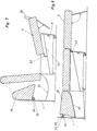
- the coupling 31 of a jumping fitting provided with parallelogram links 32, 33 is attached to the foot part 9.
- the web 34 of this fitting is pivotably mounted, namely about the axis 35 in the pull-out part 6.
- the foot part 9 can therefore be easily removed from the spring support according to the spring 36
- Pull-out part 6 are lifted in order to then be pivoted to the floor by pivoting about axis 35.
- the otherwise blocking the way cover plate 37 is pivotally mounted and connected to the handlebar 33 via a train 38, so that this plate can swing out and in.
Abstract
Description
Die Erfindung betrifft ein Sitzmöbel, welches in ein Bett, dessen Liegefläche von drei Polstereinheiten, nämlich einem Kopfteil, einem Mittelteil und einem Fußteil, gebildet wird, umwandelbar ist. Dieses Sitzmöbel besteht aus einem eine Rückenlehne tragenden Grundteil, welcher seitlich mit Führungsschienen versehen ist, auf denen das hintere Ende eines Ausziehteiles geführt ist, dessen vorderes Ende mit Rollen versehen ist.The invention relates to a piece of seating furniture which can be converted into a bed, the lying surface of which is formed by three cushion units, namely a head part, a middle part and a foot part. This seating furniture consists of a base part supporting a backrest, which is laterally provided with guide rails on which the rear end of a pull-out part is guided, the front end of which is provided with rollers.
Die bekannten Sitzmöbel dieser Art waren insofern sehr konpliziert aufgebaut, als sie über zwei aus einem Grundteil ausziehbare und teleskopartig ineinander geführte Ausziehteile verfügten, von denen der innere bzw. vordere Ausziehteil mit dem Fußteil einstückig ausgebildet war und der Mittelteil, der bei eingeschobener Lage der beiden Ausziehteile auf dem Fußteil lag, nach dem Ausziehen der beiden Ausziehteile um 180° geschwenkt wurde und damit auf dem äußeren, hinteren Ausziehteil zur Auflage kam. Dies hatte aber zur Folge, daß sich die Liegehöhe, die bei einem normalen Bett etwa der Sitzhöhe von 42 cm entspricht, erheblich verminderte (etwa auf die Hälfte), was besonders ältere und gebrechliche Personen als unangenehm empfanden.The known seating of this type was of a very complex design in that it had two pull-out parts which could be pulled out from a base and telescoped into one another, of which the inner or front pull-out part was formed in one piece with the foot part and the middle part, which when the two were in the inserted position Pull-out parts lay on the foot section, after the two pull-out parts had been pulled out they were swiveled by 180 ° and thus came to rest on the outer, rear pull-out part. However, this had the consequence that the lying height, which corresponds to the seat height of 42 cm for a normal bed, decreased considerably (about half), which was particularly uncomfortable for older and frail people.
Die Erfindung setzt sich zum Ziel, die angeführten Nachteile zu beseitigen und ein Sitzmöbel der eingangs genannten Art zu schaffen, welches eine der Sitzhöhe entsprechende Liegehöhe besitzt und einfach und robust in seinem Aufbau und billig in seiner Herstellung ist und welches es darüber hinaus möglich macht, sowohl die Sitzfläche des Sitzmöbels als auch den Mittelteil der Liegefläche des Bettes mit einer harten und daher gegen Abnützungen des Stoffbezuges weitgehend verhindernden Federung zu versehen.The aim of the invention is to eliminate the disadvantages mentioned and to create a piece of seating furniture of the type mentioned at the outset which has a lying height corresponding to the seat height and is simple and robust in its construction and inexpensive to manufacture and which also makes it possible with both the seat of the seating furniture and the middle part of the bed surface a hard and therefore largely to prevent wear of the fabric cover suspension.
Dieses Ziel wird gemäß der Erfindung vor allem dadurch erreicht, daß der Ausziehteil die Form einer Schublade aufweist, an deren Oberseite der Mittelteil als Deckel angelenkt ist, wobei im Ausziehteil der Fußteil herausschwenk- und/oder schiebbar gelagert ist.This aim is achieved according to the invention above all in that the pull-out part has the shape of a drawer, on the upper side of which the middle part is articulated as a cover, the foot part being pivoted and / or slidably mounted in the pull-out part.
Gemäß einer weiteren Ausgestaltung der Erfindung ist der Fußteil gegenüberliegend dem Mittelteil am Ausziehteil angelenkt, wobei bei Verwendung des Möbels zum Sitzen der Fußteil und der den Hohlraum oben abschließende Mittelteil mit ihren Rückseiten aneinanderliegen.According to a further embodiment of the invention, the foot part is articulated on the pull-out part opposite the middle part, the back parts of the foot part and the middle part closing off the cavity being in contact with one another when the furniture is used for sitting.
Im Rahmen der Erfindung ist aber auch eine Ausführungsform möglich, bei der der Fußteil an seitlichen Armen angelenkt ist, die ihrerseits im Ausziehteil schwenkbar gelagert sind, wobei im eingeklappten Zustand des Fußteiles dieser mit der gepolsterten Seite nach oben liegt. Ein Verschwenken des Fußteiles um 180° ist bei dieser Ausführungsform nicht notwendig.In the context of the invention, however, an embodiment is also possible in which the foot part is articulated on side arms, which in turn are pivotably mounted in the pull-out part, the foot part lying in the folded-up state with the padded side upward. A pivoting of the foot part by 180 ° is not necessary in this embodiment.
Soll ein Verschwenken des Fußteiles überhaupt vermieden werden, kann der Fußteil an Führungen verschiebbar sein, die innerhalb des Ausziehteiles schräg nach oben führend angeordnet sind.If pivoting of the foot part is to be avoided at all, the foot part can be displaceable on guides which are arranged so as to lead obliquely upwards within the pull-out part.
Das Herausheben des Fußteiles aus dem Ausziehteil wird bei einer Ausführungsform wesentlich erleichtert, bei der der Fußteil an einem innerhalb des Ausziehteiles angeordneten, mit Parallelogrammlenkern versehenen Springaufbeschlag befestigt ist, dessen Steg am Ausziehteil schwenkbar gelagert ist.Lifting the foot part out of the pull-out part is made considerably easier in one embodiment in which the foot part is fastened to a spring-loaded fitting arranged within the pull-out part and provided with parallelogram links, the web of which is pivotably mounted on the pull-out part.
Im Rahmen der Erfindung ist es möglich, die Rückenlehne mit dem Grundteil starr zu verbinden, in welchem Falle eine große Freizügigkeit bei der Gestaltung der Rückenlehne gegeben ist. Bei einer solchen Ausführungsform kann als Kopfteil ein in den Ausziehteil eingelegter loses Kissen verwendet werden. Es ist aber auch möglich, die Rückenlehne als Kopfteil zu verwenden. Eine besonders zweckmäßige derartige Ausführungsform zeichnet sich dadurch aus, daß am Grundteil ein Ende eines flexiblen Streifens aus Segeltuch, Drillich od. dgl, befestigt ist, dessen gegenüberliegendes Ende mit dem Ausziehteil verbunden ist, wobei bei ausgezogenem Ausziehteil die Rückenlehne als s Kopfteil auf den flexiblen Streifen legbar ist. Die Rückenlehne kann dabei auf einfache Art mit dem Grundteil über bloß ein Stoffscharnier schwenkbar verbunden sein. Bei einer solchen Ausführungsform werden einerseits teure Beschläge eingespart, anderseits wird eine sichere Halterung des auf dem flexiblen Streifen liegenden Rückenteiles erreicht.In the context of the invention it is possible to rigidly connect the backrest to the base part, in which case there is great freedom of movement in the design of the backrest. In such an embodiment, a loose cushion inserted into the pull-out part can be used as the head part. But it is also possible to use the backrest as a head part. A particularly expedient embodiment of this type is characterized in that one end of a flexible strip of canvas, drillich or the like, is attached to the base part, the opposite end of which ver with the pull-out part is bound, the backrest can be placed as s head part on the flexible strip when the pull-out part is pulled out. The backrest can be pivotally connected to the base part simply by means of a fabric hinge. In such an embodiment, expensive fittings are saved on the one hand, and on the other hand a secure mounting of the back part lying on the flexible strip is achieved.
Nachstehend ist die Erfindung an Hand von in den Zeichnungen dargestellten Ausführungsbeispielen näher beschrieben. Dabei zeigen: Fig. 1 eine Ausführungsform des Möbels in der zum Sitzen bestimmten Lage, Fig. 2 dieses Möbel nach Ausziehen des Ausziehteiles, Fig. 3 dieses Möbel nach Hochklappen des Mittelteiles und des Fußteiles, Fig. 4 das in ein Bett umgewandelte Möbel, Fig. 5 ein weiteres Ausführungsbeispiel in einer Zwischenstellung, Fig. 6 das gleiche Möbel in einer für alle Ausführungsformen der Erfindung typischen Ruhestellung, Fig. 7 eine andere Ausführungsform der Erfindung in einer Zwischenstellung, Fig. 8 diese Ausführungsform in der Liegestellung und Fig. 9 eine mit einem Springaufbeschlag ausgestattete Variante in verschiedenen Zwischenstellungen.The invention is described in more detail below on the basis of exemplary embodiments illustrated in the drawings. 1 shows an embodiment of the piece of furniture in the position intended for sitting, FIG. 2 this piece of furniture after the pull-out part has been pulled out, FIG. 3 this piece of furniture after the middle part and the foot part have been folded up, FIG. 4 the piece of furniture converted into a bed, 5 shows a further embodiment in an intermediate position, FIG. 6 shows the same piece of furniture in a rest position typical of all embodiments of the invention, FIG. 7 shows another embodiment of the invention in an intermediate position, FIG. 8 shows this embodiment in the lying position and FIG. 9 a variant equipped with a jumping bracket in various intermediate positions.
Gemäß den Fig. 1 bis 5 besitzt ein in ein Bett umwandelbares Sitzmöbel einen im Grundriß im wesentlichen U-förmigen, eine Rückenlehne 2 tragenden Grundteil 1, welcher nach vorne offen ist und im Bereich seiner beiden, die Schenkeln des U bildenden Seitenwände 3 mit nach hinten geneigten Führungsschienen 4 versehen ist. Auf diesen Führungsschienen 4 ist das hintere Ende 5 eines Ausziehteiles 6 geführt. Das vordere Ende 7 des Ausziehteiles 6 ist mit Rollen 8 versehen. Die Rückseite des Grundteiles 1 ist mit 1' bezeichnet.1 to 5 has a seat convertible into a bed with a substantially U-shaped outline, a
Der Ausziehteil 6 trägt an beiden Enden seiner Oberseite Schwenkachsen 11, 12, welche zumindest angenähert in der gleichen Horizontalebene liegen und an denen ein Mittelteil 10 und ein Fußteil 9 angelenkt sind. Dabei ist der Mittelteil 10, der in beiden Verwendungslagen des Sitzmöbels auf der Oberseite des Ausziehteiles 6 aufliegt, an der der Rückseite 1' des Grundteiles 1 benachbarten Schwenkachse 11, der Fußteil 9 hingegen an der von der Rückseite 1' entfernten Schwenkachse 12 angelenkt.The pull-out
Der Ausziehteil 6 besitzt die Form einer Schublade, deren Hohlraum zur Aufnahme des Fußteiles 9 sowie eines lose eingelegten Kopfteiles 14 bestimmt ist. Bei der Verwendung des Möbels zum Sitzen liegen der Fußteil 9, der in den Hohlraum der Schublade hineingeschwenkt ist, und der den Hohlraum an seiner Oberseite abschließende Mittelteil 10 mit ihren Rückseiten aneinander.The pull-out
Um den Fußteil 9 in seiner um 180° ausgeschwenkten Lage abzustützen, ist an seiner Unterseite im Bereich des der Schwenkachse gegenüberliegenden Endes ein Stützbügel 15 schwenkbar gelagert, dessen Schwenkwinkel α z.B. durch Anschläge od. dgl. auf einen Wert von etwa über 90° begrenzt ist. Normaler Weise wird dieser Stützbügel 15 von Hand in die Stützlage gebracht. Es wäre jedoch auch möglich, seine Schwenkbewegung durch eine Zwangssteuerung herbeizuführen, beispielsweise durch ein Hebelgestänge, welches am Ausziehteil 6 angelenkt ist.In order to support the
An seinem hinteren Ende ist der Ausziehteil 6 mit Gleitstücken versehen, die in den Führungsschienen 4 geführt sind. Um ein Zurückgleiten des Ausziehteiles aus der ausgezogenen Lage hintanzuhalten, sind die Führungsschienen an ihrem vorderen Ende mit Rasten 16 versehen, in denen die beiden Gleitstücke einrasten können und welche gleichzeitig Begrenzungsanschläge bilden.At its rear end, the pull-out
Am unteren Ende der Rückenlehne 2, die mit dem Grundteil 1 starr verbunden ist, befindet sich ein Ouerbalken 17. An diesem ist das eine Ende eines flexiblen Streifens 18 aus Drillich, Segeltuch od. dgl. befestigt, dessen gegenüberliegendes Ende 19 z.B. mit Hilfe einer angeschraubten Leiste, die in der Zeichnung nicht näher dargestellt ist, mit dem Mittelteil 10 verbunden ist. Die Breite des Streifens 18 entspricht zumindest angenähert dem Abstand des Querbalkens 17 vom Mittelteil 10 bei ausgezogenem Ausziehteil 6. Bei Verwendung des Möbels zum Sitzen bildet der Streifen 18 eine Schlaufe, die sich im Grundteil 1 zwischen dessen Rückseite 1' und der Rückseite des Ausziehteiles 6 befindet. Ist jedoch das Möbel in ein Bett umgewandelt, so ist der Streifen 18 zwischen der Rückenlehne 2 und dem Mittelteil 10 ausgespannt und kann zur Auflage des Kopfteiles 14 herangezogen werden. Da die Breite des letzteren dem Abstand zwischen der Rückenlehne 2 und dem Mittelteil 10 entspricht, wird durch das Einlegen des Kopfteiles 14 in diesen Zwischenraum eine weitere Sicherung des ausgezogenen Ausziehteiles 6 gegen Zurückgleiten herbeigeführt.At the lower end of the
Die beiden Führungsschienen 4 sind im Grundteil 1 nach vorne ansteigend angeordnet. Dies nacht es möglich, daß bei eingeschobenem Ausziehteil 6 die Oberseite des die Sitzfläche bildenden Mittelteiles 10 nach rückwärts geneigt ist, was ein angenehmes Sitzen ermöglicht, bei ausgezogenem Ausziehteil 6 hingegen horizontal verläuft, was für einen gesunden Schlaf unerläßlich ist.The two
Die Gebrauchsweise des erfindungsgerräßen Sitzmöbels ist äußerst einfach. Zunächst wird der Ausziehteil 6 aus dem Grundteil herausgezogen (Fig. 2). Im Anschluß daran wird der Mittelteil 10 etwa bis in die Vertikalebene geschwenkt und der Fußteil 9 z.B. mit Hilfe des Stützbügels 15 aus seiner in den Ausziehteil 6 versenkten Lage um 180° um seine Schwenkachse 12 gedreht (Fig. 3). Schließlich wird der Stützbügel 15 in die Raststellung bewegt, der Kopfteil 14 wird aus dem Ausziehteil 6 herausgenomnen, der Mittelteil 10 wird in seine Ausgangslage zurückgeschwenkt und der Kopfteil 14 wird in die Lücke zwischen der Rückenlehne 2 und dem Mittelteil 10 eingesetzt. Damit ist das Bett bereit zur Verwendung. Die Umwandlung des Bettes in ein Sitzmöbel erfolgt in umgekehrter Reihenfolge der einzelnen Handgriffe.The use of the seating furniture according to the invention is extremely simple. First, the pull-out
Wie aus den Zeichnungen ersichtlich ist, ist die Liegehöhe bei einem erfindungsgemäßen Möbel gleich der Sitzhöhe, was einen wesentlichen Vorteil darstellt.As can be seen from the drawings, the lying height in a piece of furniture according to the invention is equal to the seat height, which represents a significant advantage.
Das Ausführungsbeispiel nach den Fig. 5 und 6 unterscheidet sich von der ersten Ausführungsform dadurch, daß der Fußteil 9 an seitlichen Armen 20 angelenkt ist, die ihrerseits um Achsen 21 im Ausziehteil 6 schwenkbar gelagert sind. Der Fußteil 9 braucht bei seinem Herausnehmen aus dem Ausziehteil bzw. seinem Hineinklappen in diesen daher nicht um 1800 verschwenkt werden, die gepolsterte Fläche liegt vielmehr in beiden Stellungen oben.The exemplary embodiment according to FIGS. 5 and 6 differs from the first embodiment in that the
In Fig. 6 ist eine Stellung des Möbel dargestellt, die bei allen Ausführungsformen der Erfindung möglich ist und als Ruhestellung, z.B. beim Fernsehen, sehr bequem ist. Nach dem Herausklappen des Fußteiles 9 wird der Ausziehteil 6 wieder zurückgeschoben, sodaß ein auf dem Mittelteil 10 Sitzender seine Füße auf den Fußteil 9 legen kann.In Fig. 6, a position of the furniture is shown, which is possible in all embodiments of the invention and is very convenient as a rest position, for example when watching TV. After the
Beim Ausführungsbeispiel nach den Fig. 7 und 8 sind im Ausziehteil seitlich Führungen 22 angeordnet, die schräg nach oben ansteigen. Auf diesen Führungen sind gekröpfte Ansätze 23 des Fußteiles 9 gleitbar, sodaß der Fußteil 9 an einer Handschlaufe 24 aus dem Ausziehteil 6 gleitend gezogen werden kann. Die Ansätze 23 können naturgemäß auch mit Rollen versehen sein.In the embodiment according to FIGS. 7 and 8,
Überdies ist bei dieser Variante der Erfindung die Rückenlehne 25 über ein Stoffscharnier 26 am Grundteil 1 schwenkbar. Zu diesem Zweck ist ein Stoffstreifen mittels Leisten 27, 28 einerseits an der Rückenlehne 25, anderseits an einer mit dem Grundteil 1 verbundenen Leiste 29 befestigt. Ein flexibler Streifen 30 ist ähnlich dem Streifen 18 nach den Fig. 1 bis 4 am Ausziehteil 6 und am Grundteil 1 befestigt. Dieser Streifen 30 ist so lang bzw. so angeordnet, daß er, wie aus Fig. 8 ersichtlich ist, die über das Stoffscharnier 26 abgeklappte Rückenlehne 25 tragen kann. Gegenüber üblichen Gelenken bringt die Anordnung des Streifens 30 den wesentlichen Vorteil mit sich, daß die Halterung des Rückenkissens 25 sicherer ist, wobei überdies eine einfachere Anordnung ermöglicht wird. Bei Anordnung eines üblichen festen Gelenkes, um das die Rückenlehne schwenkbar ist, ergibt sich nämlich ein relativ großer Hebel sarm, durch den die Rückenlehne nach unten gedrückt werden kann.In addition, in this variant of the invention, the
Gemäß Fig. 9 ist am Fußteil 9 die Koppel 31 eines mit Parallelogramnlenkern 32, 33 versehenen Springaufbeschlages befestigt. Der Steg 34 dieses Beschlages ist jedoch im Gegensatz zu bekannten Beschlägen schwenkbar gelagert, und zwar um die Achse 35 im Ausziehteil 6. Wie in Fig. 9 gezeigt ist, kann daher der Fußteil 9 zufolge der Unterstützung durch die Feder 36 des Springaufbeschlages leicht aus dem Ausziehteil 6 gehoben werden, um anschließend unter Verschwenkung um die Achse 35 auf den Boden geschwenkt zu werden. Die sonst den Weg sperrende Abdeckplatte 37 ist schwenkbar gelagert und über einen Zug 38 mit dem Lenker 33 verbunden, sodaß diese Platte aus- und einschwenken kann.According to FIG. 9, the
Im Rahmen der Erfindung sind zahlreiche Abänderungen möglich. Insbesondere können Merkmale der einzelnen Ausführungsbeispiele mit - einander kombiniert werden.Numerous modifications are possible within the scope of the invention. In particular, features of the individual exemplary embodiments can be combined with one another.
Claims (7)
Applications Claiming Priority (4)
| Application Number | Priority Date | Filing Date | Title |
|---|---|---|---|
| AT5112/80 | 1980-10-15 | ||
| AT0511280A AT370963B (en) | 1980-10-15 | 1980-10-15 | SEAT FURNITURE CONVERTIBLE INTO A BED |
| AT0168481A AT369974B (en) | 1980-10-15 | 1981-04-13 | SEAT FURNITURE |
| AT1684/81 | 1981-04-13 |
Publications (3)
| Publication Number | Publication Date |
|---|---|
| EP0050107A2 true EP0050107A2 (en) | 1982-04-21 |
| EP0050107A3 EP0050107A3 (en) | 1982-04-28 |
| EP0050107B1 EP0050107B1 (en) | 1986-07-30 |
Family
ID=25596531
Family Applications (1)
| Application Number | Title | Priority Date | Filing Date |
|---|---|---|---|
| EP19810890162 Expired EP0050107B1 (en) | 1980-10-15 | 1981-10-06 | Sitting furniture |
Country Status (3)
| Country | Link |
|---|---|
| EP (1) | EP0050107B1 (en) |
| AT (2) | AT370963B (en) |
| DE (2) | DE3175037D1 (en) |
Cited By (4)
| Publication number | Priority date | Publication date | Assignee | Title |
|---|---|---|---|---|
| AT404787B (en) * | 1996-08-01 | 1999-02-25 | Hasag Beteiligungen Gmbh | SEAT FURNITURE |
| AT405362B (en) * | 1997-10-03 | 1999-07-26 | Hoppe Kg Hodry Metallfab | Seat which can be converted into a couch |
| AT412441B (en) * | 2003-02-07 | 2005-03-25 | Hasag Moebel | SEAT OR LIE FURNITURE |
| FR2880525A1 (en) * | 2005-01-13 | 2006-07-14 | Parisot Sieges Internat | Sofa-bed, has operating rod with U shaped gripping tube including central branch and two lateral branches articulated around bed cushion and extended by positioning branch articulated around rotation axis of seat frame |
Families Citing this family (2)
| Publication number | Priority date | Publication date | Assignee | Title |
|---|---|---|---|---|
| AT384541B (en) * | 1983-07-11 | 1987-11-25 | Hoppe Kg Hodry Metallfab | Seat that can be converted into a bed |
| AT400917B (en) * | 1993-08-19 | 1996-04-25 | Hoppe Kg Hodry Metallfab | LOCKING FOR SUPPORTS OF UPHOLSTERY COVERS OF SEAT AND LOUNGE FURNITURE |
Citations (5)
| Publication number | Priority date | Publication date | Assignee | Title |
|---|---|---|---|---|
| GB222601A (en) * | 1923-07-20 | 1924-10-09 | George James Brown | Improvements in bed settee and bed chair |
| DE815394C (en) * | 1950-03-07 | 1951-10-01 | Rheinische Polstermoebelwerke | Sofa with upper and lower upholstery that can be converted into a lounger |
| GB666804A (en) * | 1949-08-22 | 1952-02-20 | Greaves & Thomas Ltd | Improvements relating to convertible bed-settees and the like |
| AT342240B (en) * | 1976-08-11 | 1978-03-28 | Pallan Erwin | CONVERTIBLE INTO A LIVING FURNITURE |
| GB2070423A (en) * | 1980-03-01 | 1981-09-09 | Peitz & Co Stanzwerk | Sofa-bed |
-
1980
- 1980-10-15 AT AT0511280A patent/AT370963B/en not_active IP Right Cessation
-
1981
- 1981-04-13 AT AT0168481A patent/AT369974B/en not_active IP Right Cessation
- 1981-10-06 DE DE8181890162T patent/DE3175037D1/en not_active Expired
- 1981-10-06 EP EP19810890162 patent/EP0050107B1/en not_active Expired
- 1981-10-15 DE DE19818130178 patent/DE8130178U1/en not_active Expired
Patent Citations (5)
| Publication number | Priority date | Publication date | Assignee | Title |
|---|---|---|---|---|
| GB222601A (en) * | 1923-07-20 | 1924-10-09 | George James Brown | Improvements in bed settee and bed chair |
| GB666804A (en) * | 1949-08-22 | 1952-02-20 | Greaves & Thomas Ltd | Improvements relating to convertible bed-settees and the like |
| DE815394C (en) * | 1950-03-07 | 1951-10-01 | Rheinische Polstermoebelwerke | Sofa with upper and lower upholstery that can be converted into a lounger |
| AT342240B (en) * | 1976-08-11 | 1978-03-28 | Pallan Erwin | CONVERTIBLE INTO A LIVING FURNITURE |
| GB2070423A (en) * | 1980-03-01 | 1981-09-09 | Peitz & Co Stanzwerk | Sofa-bed |
Cited By (4)
| Publication number | Priority date | Publication date | Assignee | Title |
|---|---|---|---|---|
| AT404787B (en) * | 1996-08-01 | 1999-02-25 | Hasag Beteiligungen Gmbh | SEAT FURNITURE |
| AT405362B (en) * | 1997-10-03 | 1999-07-26 | Hoppe Kg Hodry Metallfab | Seat which can be converted into a couch |
| AT412441B (en) * | 2003-02-07 | 2005-03-25 | Hasag Moebel | SEAT OR LIE FURNITURE |
| FR2880525A1 (en) * | 2005-01-13 | 2006-07-14 | Parisot Sieges Internat | Sofa-bed, has operating rod with U shaped gripping tube including central branch and two lateral branches articulated around bed cushion and extended by positioning branch articulated around rotation axis of seat frame |
Also Published As
| Publication number | Publication date |
|---|---|
| ATA168481A (en) | 1982-07-15 |
| DE3175037D1 (en) | 1986-09-04 |
| DE8130178U1 (en) | 1982-04-22 |
| AT370963B (en) | 1983-05-25 |
| EP0050107A3 (en) | 1982-04-28 |
| ATA511280A (en) | 1982-10-15 |
| AT369974B (en) | 1983-02-25 |
| EP0050107B1 (en) | 1986-07-30 |
Similar Documents
| Publication | Publication Date | Title |
|---|---|---|
| DE60005810T2 (en) | FOOTREST AND FURNITURE | |
| DE2423859A1 (en) | Seating and reclining furniture | |
| CH641337A5 (en) | SEAT OR LOUNGE FURNITURE. | |
| DE2659532C2 (en) | Seating furniture that can be converted into reclining furniture | |
| EP0504129A1 (en) | Convertible settee | |
| DE6751421U (en) | BED SUPPORT. | |
| DE8310049U1 (en) | MOVABLE FURNITURE FROM THE SEAT TO THE LYING POSITION | |
| EP0050107A2 (en) | Sitting furniture | |
| DE7701585U1 (en) | FURNITURE CONVERTIBLE INTO A BED | |
| DE3214402A1 (en) | Wall construction with seating furniture inserted into a recess in the construction | |
| DE3000957A1 (en) | Convertible double bed settee - has sliding undercarriage and folding system allowing normal seat height with thick mattress sections | |
| DD203821A5 (en) | EXTENDIBLE DOUBLE BELT WITH EXTENDED STEERING PART | |
| DE2542941A1 (en) | Convertible upholstered bed chair - has pull out support frame which conforms to standard dimensions in each position | |
| DE1429334A1 (en) | Sofa convertible into a double bed | |
| DE2715989A1 (en) | SEATING FURNITURE | |
| DE807008C (en) | Sofa convertible into a double bed | |
| DE3107415A1 (en) | Bench which can be converted into a sofa bed, and fitting therefor | |
| DE8032062U1 (en) | UPHOLSTERED ARMCHAIR OR COUCH WITH ADJUSTABLE SEAT AND BACK UPHOLSTERY | |
| AT391606B (en) | Seat which can be converted into a bed | |
| AT394933B (en) | Convertible seat | |
| AT408309B (en) | SEAT, LOUNGE, FURNITURE | |
| DE3009073A1 (en) | ADJUSTABLE FURNITURE | |
| DE2659526A1 (en) | Convertible hinged sectional armchair - has movable carriage sliding on fixed frame for conversion to bed (OE 15.10.76) | |
| DE2500481C2 (en) | Swivel fitting for a sofa bed with tiltable and horizontally adjustable seat cushion | |
| DE8318492U1 (en) | SEAT FURNITURE IN THE FORM OF AN ARMCHAIR OR A SOFA |
Legal Events
| Date | Code | Title | Description |
|---|---|---|---|
| PUAI | Public reference made under article 153(3) epc to a published international application that has entered the european phase |
Free format text: ORIGINAL CODE: 0009012 |
|
| PUAL | Search report despatched |
Free format text: ORIGINAL CODE: 0009013 |
|
| AK | Designated contracting states |
Designated state(s): CH DE FR GB IT LI |
|
| AK | Designated contracting states |
Designated state(s): CH DE FR GB IT LI |
|
| 17P | Request for examination filed |
Effective date: 19820417 |
|
| RAP1 | Party data changed (applicant data changed or rights of an application transferred) |
Owner name: HASAG M. HASLBERGER GES.M.B.H. & CO. KG. |
|
| GRAA | (expected) grant |
Free format text: ORIGINAL CODE: 0009210 |
|
| AK | Designated contracting states |
Kind code of ref document: B1 Designated state(s): CH DE FR GB IT LI |
|
| PG25 | Lapsed in a contracting state [announced via postgrant information from national office to epo] |
Ref country code: IT Free format text: LAPSE BECAUSE OF FAILURE TO SUBMIT A TRANSLATION OF THE DESCRIPTION OR TO PAY THE FEE WITHIN THE PRESCRIBED TIME-LIMIT;WARNING: LAPSES OF ITALIAN PATENTS WITH EFFECTIVE DATE BEFORE 2007 MAY HAVE OCCURRED AT ANY TIME BEFORE 2007. THE CORRECT EFFECTIVE DATE MAY BE DIFFERENT FROM THE ONE RECORDED. Effective date: 19860730 Ref country code: FR Free format text: THE PATENT HAS BEEN ANNULLED BY A DECISION OF A NATIONAL AUTHORITY Effective date: 19860730 |
|
| REF | Corresponds to: |
Ref document number: 3175037 Country of ref document: DE Date of ref document: 19860904 |
|
| PG25 | Lapsed in a contracting state [announced via postgrant information from national office to epo] |
Ref country code: LI Effective date: 19861031 Ref country code: CH Effective date: 19861031 |
|
| EN | Fr: translation not filed | ||
| PLBE | No opposition filed within time limit |
Free format text: ORIGINAL CODE: 0009261 |
|
| STAA | Information on the status of an ep patent application or granted ep patent |
Free format text: STATUS: NO OPPOSITION FILED WITHIN TIME LIMIT |
|
| REG | Reference to a national code |
Ref country code: CH Ref legal event code: PL |
|
| GBPC | Gb: european patent ceased through non-payment of renewal fee | ||
| 26N | No opposition filed | ||
| PG25 | Lapsed in a contracting state [announced via postgrant information from national office to epo] |
Ref country code: GB Effective date: 19881118 |
|
| PGFP | Annual fee paid to national office [announced via postgrant information from national office to epo] |
Ref country code: DE Payment date: 20001030 Year of fee payment: 20 |