EP0049967A1 - Procédé de production de l'ammoniac - Google Patents
Procédé de production de l'ammoniac Download PDFInfo
- Publication number
- EP0049967A1 EP0049967A1 EP81304439A EP81304439A EP0049967A1 EP 0049967 A1 EP0049967 A1 EP 0049967A1 EP 81304439 A EP81304439 A EP 81304439A EP 81304439 A EP81304439 A EP 81304439A EP 0049967 A1 EP0049967 A1 EP 0049967A1
- Authority
- EP
- European Patent Office
- Prior art keywords
- gas
- hydrogen
- synthesis
- ammonia
- range
- Prior art date
- Legal status (The legal status is an assumption and is not a legal conclusion. Google has not performed a legal analysis and makes no representation as to the accuracy of the status listed.)
- Ceased
Links
Images
Classifications
-
- C—CHEMISTRY; METALLURGY
- C01—INORGANIC CHEMISTRY
- C01C—AMMONIA; CYANOGEN; COMPOUNDS THEREOF
- C01C1/00—Ammonia; Compounds thereof
- C01C1/02—Preparation, purification or separation of ammonia
- C01C1/04—Preparation of ammonia by synthesis in the gas phase
- C01C1/0405—Preparation of ammonia by synthesis in the gas phase from N2 and H2 in presence of a catalyst
- C01C1/0476—Purge gas treatment, e.g. for removal of inert gases or recovery of H2
-
- C—CHEMISTRY; METALLURGY
- C01—INORGANIC CHEMISTRY
- C01B—NON-METALLIC ELEMENTS; COMPOUNDS THEREOF; METALLOIDS OR COMPOUNDS THEREOF NOT COVERED BY SUBCLASS C01C
- C01B3/00—Hydrogen; Gaseous mixtures containing hydrogen; Separation of hydrogen from mixtures containing it; Purification of hydrogen
- C01B3/02—Production of hydrogen or of gaseous mixtures containing a substantial proportion of hydrogen
- C01B3/025—Preparation or purification of gas mixtures for ammonia synthesis
-
- C—CHEMISTRY; METALLURGY
- C01—INORGANIC CHEMISTRY
- C01C—AMMONIA; CYANOGEN; COMPOUNDS THEREOF
- C01C1/00—Ammonia; Compounds thereof
- C01C1/02—Preparation, purification or separation of ammonia
- C01C1/04—Preparation of ammonia by synthesis in the gas phase
- C01C1/0405—Preparation of ammonia by synthesis in the gas phase from N2 and H2 in presence of a catalyst
-
- Y—GENERAL TAGGING OF NEW TECHNOLOGICAL DEVELOPMENTS; GENERAL TAGGING OF CROSS-SECTIONAL TECHNOLOGIES SPANNING OVER SEVERAL SECTIONS OF THE IPC; TECHNICAL SUBJECTS COVERED BY FORMER USPC CROSS-REFERENCE ART COLLECTIONS [XRACs] AND DIGESTS
- Y02—TECHNOLOGIES OR APPLICATIONS FOR MITIGATION OR ADAPTATION AGAINST CLIMATE CHANGE
- Y02P—CLIMATE CHANGE MITIGATION TECHNOLOGIES IN THE PRODUCTION OR PROCESSING OF GOODS
- Y02P20/00—Technologies relating to chemical industry
- Y02P20/50—Improvements relating to the production of bulk chemicals
- Y02P20/52—Improvements relating to the production of bulk chemicals using catalysts, e.g. selective catalysts
Definitions
- This invention relates to an ammonia production process capable of operation at a relatively low rate of energy consumption per unit quantity of product.
- An ammonia production process comprises a synthesis gas generation section in which usually a carbonaceous feedstock is reacted with steam and air and the resulting gas is processed to give a purified ammonia synthesis gas and compressed, and a synthesis section in which the synthesis gas is reacted to ammonia over a synthesis catalyst and ammonia is recovered in liquid form. Compression of the synthesis gas consumes much power, and accordingly efforts have been made, especially over the last 30 years, to decrease power consumption by increasing the pressure at which the synthesis gas is generated and fed to the compressor, and by decreasing the pressure in the synthesis section.
- a particular advantage is that the flow rate of gas in the hydrogen recovery can be kept at a substantially lower level than if the hydrogen recovery rate were large enough to bring the ratio to 3.0. Accordingly power consumption is usefully decreased.
- an ammonia production process comprises
- Steps (a) to (f) characterise the process of our European published application 993.
- the H 2 :N 2 molar ratio is preferably in the range 1.5 to 2.3 in the gas entering the synthesis catalyst. Whatever its ratio within the defined broad or preferred range, it is maintained preferably within 20% of the ratio in the fresh synthesis gas produced in step (d). By this means the rate of flow of the hydrogen recovery stream and thus the power consumption are limited.
- the required H 2 :N 2 molar ratio in fresh synthesis gas can be attained without excessive catalyst outlet temperatures provided the steam to carbon ratio in the primary and secondary reforming steps is high enough.
- a steam ratio in the range 4 - 8 is preferably used.
- the primary reforming final catalyst bed preferably operates at an outlet methane content in the range 25 - 35% v / v on a dry basis.
- the methane content of the gas leaving the secondary reformer is preferably in the range 1.5 to 3% on a dry basis. Such methane contents are substantially higher than have previously been considered suitable for ammonia production.
- a very suitable catalyst comprises nickel on a refractory secondary support on a metal or alloy primary support, as described in our copending European application 80301982 (publication 21736).
- the preheater for one or more of the primary reforming steps and the secondary reformer is preferably a pressurised furnace.
- the pressure of the gases brought into heat exchange with the reactants is suitably at least 5 bar abs and preferably within 30 bar abs of the pressure of the reactants.
- the furnace is pressurised or not, it is an advantage that it can readily be designed to accept fuels other than gaseous or vaporised hydrocarbons. Consequently the process of the invention has a flexibility of plant design not available in the conventional process using a steam reforming furnace.
- the furnace can be of the fluidised solid fuel type.
- the steam-to-gas volume ratio is preferably at least 0.8 which, with suitable temperature control, enables the outlet CO content to be low enough for final removal by methanation.
- the outlet C0 content can be up to 2.0% v / v on a dry basis instead of up to about 0.5% in a conventional shift process to be followed by methanation, because each molecule of CO removed by oxidation results in one lost H 2 molecule only.
- the advantages of such a shift process are that more heat can be recovered from the hot gas before shift and that at pressures over 30 bar abs. the temperature can be well above the dewpoint of steam and catalyst damage avoided.
- the catalyst can be supported copper, suitably with zinc oxide and one or more refractory oxides such as alumina.
- the invention provides a process for producing hydrogen by the steps of
- the oxidising agent can be air.
- the selective oxidation catalyst is suitably supported platinum (0.01 to 2.0% w / w ) containing possibly one or more of manganese, iron, cobalt or nickel as a promoter.
- platinum 0.01 to 2.0% w / w
- a description of a suitable selective oxidation process is given in UK 1555826 and in the articles by Colby et al (23rd Symposium on safety in ammonia plants and related facilities, Am. Inst. Chem. Engrs. Conv., Miami, November 1978) and Bonacci et al. (Am. Inst. Chem. Engrs. Symposium, Denver, August 1977).
- the gas is compressed preferably by 20 - 80 bar, in a single-barrel compressor.
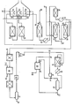
- the hydrocarbon feedstock, natural gas, is desulphurised by known means (not shown) and fed at 10 to the lower portion of packed tower 12, in which it rises through a falling stream of hot water fed in at 14 from a source to be described.
- the resulting water-saturated gas is mixed, if necessary, with steam at 16. (In an alternative process, shown by the dotted line, towers 12 and 38 are not used and all the steam is added as such at 16).
- the mixture is preheated to 700 0 C in furnace 18 fired at 20 with natural gas, which for this purpose need not be thoroughly, if at all, desulphurised.
- the heated gas is then passed over a supported nickel catalyst in insulated reactor 22.
- the endothermic methane/steam reaction takes place and the temperature falls, reaching 564 C at the catalyst outlet.
- the resulting gas is then reheated to 700°C, in furnace 24 and passed over a supported nickel catalyst in insulated reactor 26.
- further methane/steam reaction takes place and the temperature falls, reaching 689°C at the catalyst outlet.
- the resulting gas is reheated to 700°C and passed into secondary reformer 30.
- it encounters a stream of hot air (700°C) fed in at 32.
- the temperature rises initially as hydrogen burns with a flame, but over the catalyst further methane/steam reaction takes place and the temperature falls to 857°C at the catalyst bed outlet.
- the temperature and rate of feed of air are chosen so that the gas leaving 30 contains nitrogen in excess of what can react later with hydrogen to produce ammonia. It also contains methane to an extent that would normally be regarded as excessive in ammonia synthesis gas: this is preferred because the feedstock economy due to more complete methane reaction would entail extra energy consumption in compressing air and in removing nitrogen later or, alternatively or additionally, would require higher fuel consumption in furnaces 18, 24 and 28 or even a further heating and reaction step.
- Furnaces 18, 24 and 28 include flue gas heat recoveries such as combustion air preheaters and boiler feed water heaters but for the sake of clarity these are not shown.
- Gas leaving secondary reformer 30 is cooled at 34, which represents heat recovery by high pressure steam generation and one or more of boiler feed water heating and natural gas preheating.
- the cooled gas now at about 300°C, is passed into shift reactor 36 and there it reacts exothermically over a copper-containing catalyst and becomes heated to 335 0 C.
- the gas is cooled with heat recovery in boiler 37. It is contacted with water in packed tower 38 and there cooled and depleted of part of its content of steam.
- the resulting heated water is passed 14 into tower 12 already mentioned.
- the cool water fed to tower 38 at 40 is derived in part from tower 12 in which heated water from the bottom of tower 38 is cooled by evaporation and partly from supplementary water fed in at 42 from external supplies or from point 50 or 58 to be described.
- Water-depleted gas leaving tower 38 overhead is reacted with air fed at 46 over a noble metal catalyst in selective oxidation unit 44.
- the CO-free gas leaving 44 is passed to cooling, water-removal any C0 2- removal units, which are conventional and are indicated generally by'item 48.
- the water contains dissolved carbon dioxide but with simple purification can be fed to point 42.
- the carbon dioxid E can be expanded in an engine to recover energy.
- the gas contains residual C02, and this is made harmless by preheating the gas and reacting it over a supported nickel catalyst in methanation reactor 54.
- the gas is then cooled, largely freed of water in catchpot 56 and thoroughly dried by adsorption in unit 60. Water taken at 58 from catchpot 56 can be used at point 42.
- the dried gas is compressed at 62, mixed at 64 with recycle gas to be described, heated to synthesis inlet temperature and fed to reactor 66 (this reactor is shown with a single catalyst bed but in practice would include a plurality of beds and conventional means for feed gas preheating and temperature control. It is, however, preferred in any event to have feed gas preheater 67 upstream of part of the catalyst, so that hot gas from the downstream-most bed can pass to external heat recovery 68 without cooling). After heat recovery 68 the gas is cooled by conventional means (not shown) including moderate refrigeration, to below the dewpoint of ammonia and passed to catchpot 70 from which liquid product ammonia is run off at 72.
- Unreacted gas passes out overhead; at this stage it contains less hydrogen per nitrogen molecule than the gas fed to reactor 66, because ammonia formation uses three H 2 molecules per nitrogen molecule, but at 74 it receives a feed of hydrogen-rich gas to be described below.
- the mixed gas is fed to circulator 76, which increases its pressure by 10 - 20%, and is then divided at 78 into a synthesis recycle stream (which is fed to point 64) and a hydrogen recovery stream. This stream is fed to separation section 80. Here it is washed with water to remove ammonia, dried and resolved cryogenically or by absorption or selective diffusion into the hydrogen-rich stream fed to point 74 and a waste stream 86, which may have fuel value.
- the aqueous ammonia is distilled under pressure and the resulting anhydrous ammonia is fed out at 84 to the main product offtake 72.
- the table sets out the process conditions, gas compositions and hourly flow rates in a process for making 1000 metric tons per day of ammonia from a natural gas of average composition CH 3.88 containing 2.4% v /v of nitrogen and 0.1% v lv of C0 2 . This process follows the dotted paths on the flowsheet.
Landscapes
- Chemical & Material Sciences (AREA)
- Organic Chemistry (AREA)
- Inorganic Chemistry (AREA)
- Chemical Kinetics & Catalysis (AREA)
- Analytical Chemistry (AREA)
- Engineering & Computer Science (AREA)
- Combustion & Propulsion (AREA)
- Hydrogen, Water And Hydrids (AREA)
Applications Claiming Priority (2)
| Application Number | Priority Date | Filing Date | Title |
|---|---|---|---|
| GB8033131 | 1980-10-14 | ||
| GB8033131 | 1980-10-14 |
Publications (1)
| Publication Number | Publication Date |
|---|---|
| EP0049967A1 true EP0049967A1 (fr) | 1982-04-21 |
Family
ID=10516667
Family Applications (1)
| Application Number | Title | Priority Date | Filing Date |
|---|---|---|---|
| EP81304439A Ceased EP0049967A1 (fr) | 1980-10-14 | 1981-09-25 | Procédé de production de l'ammoniac |
Country Status (8)
| Country | Link |
|---|---|
| US (1) | US4383982A (fr) |
| EP (1) | EP0049967A1 (fr) |
| JP (1) | JPS57135720A (fr) |
| AU (1) | AU547395B2 (fr) |
| CA (1) | CA1181571A (fr) |
| IN (1) | IN158868B (fr) |
| NO (1) | NO160655C (fr) |
| NZ (1) | NZ198538A (fr) |
Cited By (12)
| Publication number | Priority date | Publication date | Assignee | Title |
|---|---|---|---|---|
| EP0093502A1 (fr) * | 1982-04-14 | 1983-11-09 | Imperial Chemical Industries Plc | Procédé de production de l'ammoniac |
| GB2154566A (en) * | 1984-02-07 | 1985-09-11 | Union Carbide Corp | Process and apparatus for ammonia synthesis gas production |
| GB2155456A (en) * | 1984-01-23 | 1985-09-25 | Toyo Engineering Corp | Process for refining an ammonia synthesis gas |
| EP0160412A2 (fr) * | 1984-04-25 | 1985-11-06 | Imperial Chemical Industries Plc | Synthèse de l'ammoniac |
| WO1986000286A1 (fr) * | 1984-06-30 | 1986-01-16 | Stamicarbon B.V. (Licensing Subsidiary Of Dsm) | Procede de preparation d'ammoniac |
| EP0179392A2 (fr) * | 1984-10-16 | 1986-04-30 | The M. W. Kellogg Company | Procédé de synthèse d'ammoniac |
| US4592903A (en) * | 1983-11-10 | 1986-06-03 | Exxon Research & Engineering Co. | Low severity hydrocarbon steam reforming process |
| EP0236037A2 (fr) * | 1986-02-26 | 1987-09-09 | Foster Wheeler Energy Limited | Synthèse d'ammoniac |
| US4755361A (en) * | 1984-02-07 | 1988-07-05 | Union Carbide Corporation | Apparatus for ammonia synthesis gas production |
| WO2010088327A3 (fr) * | 2009-01-30 | 2010-12-02 | Basf Catalysts Llc | Catalyseur permettant la production d'ammoniac à partir d'un hydrocarbure et d'oxydes d'azote |
| EP2316792A1 (fr) * | 2009-10-27 | 2011-05-04 | Ammonia Casale S.A. | Procédé de production d'ammoniac |
| EP4054979B1 (fr) | 2019-11-08 | 2023-11-29 | Casale Sa | Contrôle d'une boucle de synthèse d'ammoniac à charge partielle |
Families Citing this family (17)
| Publication number | Priority date | Publication date | Assignee | Title |
|---|---|---|---|---|
| GB8521649D0 (en) * | 1985-08-30 | 1985-10-02 | Ici Plc | Hydrogen production |
| US4721611A (en) * | 1984-03-02 | 1988-01-26 | Imperial Chemical Industries Plc | Hydrogen production |
| US4568531A (en) * | 1984-10-16 | 1986-02-04 | The M. W. Kellogg Company | Ammonia purge gas conversion |
| US4568532A (en) * | 1984-10-16 | 1986-02-04 | The M. W. Kellogg Company | Supplemental ammonia synthesis |
| GB8728882D0 (en) * | 1987-12-10 | 1988-01-27 | Ici Plc | Hydrogen |
| US5685890A (en) * | 1987-12-17 | 1997-11-11 | Osaka Gas Company Limited | Process for steam reforming of hydrocarbons |
| US5068058A (en) * | 1989-05-04 | 1991-11-26 | Air Products And Chemicals, Inc. | Production of ammonia synthesis gas |
| JP2812486B2 (ja) * | 1989-05-15 | 1998-10-22 | 大阪瓦斯株式会社 | 炭化水素の水蒸気改質方法 |
| US5911964A (en) * | 1993-06-25 | 1999-06-15 | Cosmo Research Institute | Method for reducing carbon dioxide using a catalyst for reduction of carbon dioxide |
| US5935544A (en) * | 1996-06-06 | 1999-08-10 | Brown & Root, Inc. | Moderate excess nitrogen Braun Purifier™ process and method for retrofitting non-Braun Purifier™ ammonia plants |
| ATE200884T1 (de) * | 1997-01-22 | 2001-05-15 | Haldor Topsoe As | Erzeugung eines synthesegases durch dampfreformierung unter verwendung eines katalysierten hardware |
| US20020165417A1 (en) * | 2001-03-14 | 2002-11-07 | Toyo Engineering Corporation | Process for producing synthesis gas |
| WO2008141784A2 (fr) * | 2007-05-21 | 2008-11-27 | Uhde Gmbh | Procédé de refroidissement d'un gaz de processus renfermant de l'hydrogène et de la vapeur d'eau, issu d'une installation de production d'hydrogène |
| US8889093B2 (en) | 2010-09-16 | 2014-11-18 | Kellogg Brown & Root Llc | High pressure cyrogenic process and system for producing ammonia products |
| EP2589574B1 (fr) | 2011-11-02 | 2015-10-21 | Casale Sa | Procédé pour la régulation de charge d'une installation de fabrication d'ammoniac |
| CN103613070B (zh) * | 2013-12-09 | 2015-08-19 | 山东洪达化工有限公司 | 合成氨混合气提氢纯氢自动配入合成气系统 |
| US20160214910A1 (en) * | 2015-01-27 | 2016-07-28 | Forrest A. King | Natural Gas Reactors and Methods |
Citations (7)
| Publication number | Priority date | Publication date | Assignee | Title |
|---|---|---|---|---|
| US3081268A (en) * | 1961-02-07 | 1963-03-12 | Jr Walton H Marshall | Ammonia synthesis gas process |
| GB1043377A (fr) * | 1964-06-08 | 1966-09-21 | ||
| GB1156002A (en) * | 1965-10-22 | 1969-06-25 | C F Brown & Co | Process and Apparatus for Reforming Hydrocarbons. |
| FR1604197A (en) * | 1968-12-30 | 1971-07-26 | Reforming of hydrocarbons to obtain - ammonia synthesis gas | |
| US3795485A (en) * | 1971-06-28 | 1974-03-05 | Fluor Corp | Synthesis gas generation apparatus |
| US3947551A (en) * | 1974-05-29 | 1976-03-30 | The Benfield Corporation | Ammonia synthesis |
| EP0000993A1 (fr) * | 1977-08-22 | 1979-03-07 | Imperial Chemical Industries Plc | Procédé pour la production d'ammoniac |
Family Cites Families (1)
| Publication number | Priority date | Publication date | Assignee | Title |
|---|---|---|---|---|
| US3598527A (en) * | 1968-10-11 | 1971-08-10 | Pullman Inc | Ammonia and methanol production |
-
1981
- 1981-09-25 EP EP81304439A patent/EP0049967A1/fr not_active Ceased
- 1981-09-30 US US06/307,514 patent/US4383982A/en not_active Expired - Fee Related
- 1981-10-01 IN IN635/DEL/81A patent/IN158868B/en unknown
- 1981-10-02 NZ NZ198538A patent/NZ198538A/en unknown
- 1981-10-07 NO NO813391A patent/NO160655C/no unknown
- 1981-10-09 AU AU76224/81A patent/AU547395B2/en not_active Ceased
- 1981-10-09 CA CA000387686A patent/CA1181571A/fr not_active Expired
- 1981-10-14 JP JP56164047A patent/JPS57135720A/ja active Pending
Patent Citations (7)
| Publication number | Priority date | Publication date | Assignee | Title |
|---|---|---|---|---|
| US3081268A (en) * | 1961-02-07 | 1963-03-12 | Jr Walton H Marshall | Ammonia synthesis gas process |
| GB1043377A (fr) * | 1964-06-08 | 1966-09-21 | ||
| GB1156002A (en) * | 1965-10-22 | 1969-06-25 | C F Brown & Co | Process and Apparatus for Reforming Hydrocarbons. |
| FR1604197A (en) * | 1968-12-30 | 1971-07-26 | Reforming of hydrocarbons to obtain - ammonia synthesis gas | |
| US3795485A (en) * | 1971-06-28 | 1974-03-05 | Fluor Corp | Synthesis gas generation apparatus |
| US3947551A (en) * | 1974-05-29 | 1976-03-30 | The Benfield Corporation | Ammonia synthesis |
| EP0000993A1 (fr) * | 1977-08-22 | 1979-03-07 | Imperial Chemical Industries Plc | Procédé pour la production d'ammoniac |
Non-Patent Citations (1)
| Title |
|---|
| Chemical Engineering Progress, Vol. 60, No. 1, January 1967 New York G.E. HAYS et al. "Ammonia Synthesis Plant Kinetics" pages 61 to 65 * |
Cited By (18)
| Publication number | Priority date | Publication date | Assignee | Title |
|---|---|---|---|---|
| EP0093502A1 (fr) * | 1982-04-14 | 1983-11-09 | Imperial Chemical Industries Plc | Procédé de production de l'ammoniac |
| US4592903A (en) * | 1983-11-10 | 1986-06-03 | Exxon Research & Engineering Co. | Low severity hydrocarbon steam reforming process |
| GB2155456A (en) * | 1984-01-23 | 1985-09-25 | Toyo Engineering Corp | Process for refining an ammonia synthesis gas |
| US4755361A (en) * | 1984-02-07 | 1988-07-05 | Union Carbide Corporation | Apparatus for ammonia synthesis gas production |
| GB2154566A (en) * | 1984-02-07 | 1985-09-11 | Union Carbide Corp | Process and apparatus for ammonia synthesis gas production |
| US4592860A (en) * | 1984-02-07 | 1986-06-03 | Union Carbide Corporation | Process and apparatus for ammonia synthesis gas production |
| EP0160412A2 (fr) * | 1984-04-25 | 1985-11-06 | Imperial Chemical Industries Plc | Synthèse de l'ammoniac |
| EP0160412A3 (en) * | 1984-04-25 | 1988-12-28 | Imperial Chemical Industries Plc | Ammonia synthesis |
| WO1986000286A1 (fr) * | 1984-06-30 | 1986-01-16 | Stamicarbon B.V. (Licensing Subsidiary Of Dsm) | Procede de preparation d'ammoniac |
| EP0179392A3 (en) * | 1984-10-16 | 1989-01-04 | The M. W. Kellogg Company | Ammonia synthesis process |
| EP0179392A2 (fr) * | 1984-10-16 | 1986-04-30 | The M. W. Kellogg Company | Procédé de synthèse d'ammoniac |
| EP0236037A3 (en) * | 1986-02-26 | 1988-08-10 | Foster Wheeler Energy Limited | Ammonia synthesis |
| EP0236037A2 (fr) * | 1986-02-26 | 1987-09-09 | Foster Wheeler Energy Limited | Synthèse d'ammoniac |
| WO2010088327A3 (fr) * | 2009-01-30 | 2010-12-02 | Basf Catalysts Llc | Catalyseur permettant la production d'ammoniac à partir d'un hydrocarbure et d'oxydes d'azote |
| EP2316792A1 (fr) * | 2009-10-27 | 2011-05-04 | Ammonia Casale S.A. | Procédé de production d'ammoniac |
| WO2011051079A1 (fr) * | 2009-10-27 | 2011-05-05 | Ammonia Casale Sa | Procédé de production d'ammoniac |
| CN102596808A (zh) * | 2009-10-27 | 2012-07-18 | 阿梅尼亚·卡萨莱股份有限公司 | 制备氨的方法 |
| EP4054979B1 (fr) | 2019-11-08 | 2023-11-29 | Casale Sa | Contrôle d'une boucle de synthèse d'ammoniac à charge partielle |
Also Published As
| Publication number | Publication date |
|---|---|
| NZ198538A (en) | 1985-01-31 |
| US4383982A (en) | 1983-05-17 |
| AU547395B2 (en) | 1985-10-17 |
| JPS57135720A (en) | 1982-08-21 |
| AU7622481A (en) | 1982-04-22 |
| CA1181571A (fr) | 1985-01-29 |
| NO813391L (no) | 1982-04-15 |
| NO160655B (no) | 1989-02-06 |
| NO160655C (no) | 1989-05-16 |
| IN158868B (fr) | 1987-02-07 |
Similar Documents
| Publication | Publication Date | Title |
|---|---|---|
| US4383982A (en) | Ammonia production process | |
| EP0093502B2 (fr) | Procédé de production de l'ammoniac | |
| US4618451A (en) | Synthesis gas | |
| US4910228A (en) | Methanol | |
| US4298588A (en) | Ammonia production process | |
| CN108368037B (zh) | 生产甲醛稳定的脲的整合方法 | |
| US4725380A (en) | Producing ammonia synthesis gas | |
| AU680690B2 (en) | Process for the production of methanol | |
| US4367206A (en) | Method for producing methanol and ammonia | |
| CN107250106B (zh) | 用于生产甲醛稳定化的尿素的整合方法 | |
| CA3010549C (fr) | Procede et usine de production d'ammoniac a base de reformage autothermique | |
| CN113795460A (zh) | 基于atr的氢气方法和设备 | |
| CN107428650B (zh) | 用于生产甲醛的方法 | |
| US3940428A (en) | Methanol production | |
| EP0601956B1 (fr) | Procédé de préparation d'un gaz riche en oxyde de carbone | |
| US4264567A (en) | Method for producing a hydrogen-containing gas | |
| GB2139644A (en) | Synthesis gas | |
| EP0212889B1 (fr) | Production de gaz de synthèse de l'ammoniac | |
| EP0207620B1 (fr) | Récupération de chaleur | |
| GB2084973A (en) | An integrated process for the production of methanol and ammonia | |
| JPH0459249B2 (fr) | ||
| CN114555516B (zh) | 基于atr的制氢方法和设备 |
Legal Events
| Date | Code | Title | Description |
|---|---|---|---|
| PUAI | Public reference made under article 153(3) epc to a published international application that has entered the european phase |
Free format text: ORIGINAL CODE: 0009012 |
|
| AK | Designated contracting states |
Designated state(s): DE FR GB IT NL |
|
| 17P | Request for examination filed |
Effective date: 19820922 |
|
| STAA | Information on the status of an ep patent application or granted ep patent |
Free format text: STATUS: THE APPLICATION HAS BEEN REFUSED |
|
| 18R | Application refused |
Effective date: 19841012 |
|
| RIN1 | Information on inventor provided before grant (corrected) |
Inventor name: PINTO, ALWYN |