EP0049335A2 - Dispositif de détermination de consommation routière spécifique de carburant - Google Patents
Dispositif de détermination de consommation routière spécifique de carburant Download PDFInfo
- Publication number
- EP0049335A2 EP0049335A2 EP81105665A EP81105665A EP0049335A2 EP 0049335 A2 EP0049335 A2 EP 0049335A2 EP 81105665 A EP81105665 A EP 81105665A EP 81105665 A EP81105665 A EP 81105665A EP 0049335 A2 EP0049335 A2 EP 0049335A2
- Authority
- EP
- European Patent Office
- Prior art keywords
- switch
- pulse
- speed
- hysteresis
- pulses
- Prior art date
- Legal status (The legal status is an assumption and is not a legal conclusion. Google has not performed a legal analysis and makes no representation as to the accuracy of the status listed.)
- Granted
Links
Images
Classifications
-
- G—PHYSICS
- G01—MEASURING; TESTING
- G01F—MEASURING VOLUME, VOLUME FLOW, MASS FLOW OR LIQUID LEVEL; METERING BY VOLUME
- G01F9/00—Measuring volume flow relative to another variable, e.g. of liquid fuel for an engine
- G01F9/008—Measuring volume flow relative to another variable, e.g. of liquid fuel for an engine where the other variable is the flight or running time
-
- G—PHYSICS
- G06—COMPUTING OR CALCULATING; COUNTING
- G06G—ANALOGUE COMPUTERS
- G06G7/00—Devices in which the computing operation is performed by varying electric or magnetic quantities
- G06G7/48—Analogue computers for specific processes, systems or devices, e.g. simulators
- G06G7/70—Analogue computers for specific processes, systems or devices, e.g. simulators for vehicles, e.g. to determine permissible loading of ships, centre of gravity, necessary fuel
Definitions
- the invention relates to a device for electronically determining the path-specific fuel consumption of a vehicle, in particular a motor vehicle, from volume pulses, the pulse frequency of which corresponds to the fuel flow, and an electrical variable analogous to the speed of the vehicle.
- the volume pulses In such known devices, the volume pulses, the pulse frequency of which is a measure of the flow of fuel through a line, are determined and related to a path-dependent or speed-dependent variable in order to arrive at the consumption expressed in liters per 100 kilometers.
- the . Computing devices required for this are often still relatively complex because of the digital modules and components used, so that their standard introduction into automotive technology is not readily possible, although consumption monitoring is generally desirable.
- the route-specific fuel consumption can vary within wide limits.
- the route-specific fuel consumption takes on very large values for low vehicle speeds; when the vehicle is stationary and the engine is running, this value approaches infinity.
- the object of the present invention is therefore to design a device of the type mentioned at the beginning for the electronic determination of the path-specific fuel consumption in such a way that it uses non-expensive electronic means with high accuracy - within reasonable limits - and in particular no false or misleading values indicates with very large path-specific fuel consumption.
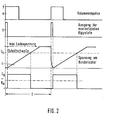
- the value range of the output pulse of the analog divider used according to the invention can be between zero and a maximum value of almost 100%, which is expressed by the pulse duty factor of the output pulse - pulse width to period.
- the circuit arrangement provided according to the invention ensures that when the input variables are exceeded in the device for determining the path-specific consumption, which in itself should have a duty cycle greater than 100%, this duty cycle remains limited to the maximum value. This condition is not easily met with normal dividers. In the device according to the invention, this is done in particular by controlling the hysteresis switch achieved by the volume pulses in such a way that after each volume pulse each output pulse of the Ilysteresis switch assumes a predetermined value, namely, for example, a low signal.
- the device can be designed in such a way that it displays the consumption very precisely in a preferred consumption range, since there is no need to take into account that a completely wrong display of the consumption can take place outside this preferred range, since here the displayed consumption in this case cannot deviate from an upper limit.
- the device is characterized by a relatively low outlay on assemblies and components, since in particular an analog / digital converter or a digital / analog converter can be dispensed with in the divider.
- the device according to the invention is advantageously further developed by a monostable multivibrator for transforming the travel pulses that are fed into the electronic switch and the hysteresis switch. This ensures precise control of these switches regardless of the curve shape of the path pulses.
- the device is advantageously further designed with the features that the capacitor is supplied with current via a voltage / current converter and a low-pass filter connected upstream thereof, which current is proportional to the voltage value dropping on an electronic tachometer. - Since this voltage value is already adapted to the travel speed of the encoder of the travel pulses and the motor vehicle, further means for adapting to the travel speed can be omitted in the device for determining the fuel consumption.
- the speed-analog voltage value can be obtained from the displacement pulses by means of a frequency-voltage converter that can be adjusted to adapt the displacement speed.
- the output pulse at the hysteresis switch of the analog divider is expediently fed to a moving coil instrument as a display device for the consumption via a low-pass filter and a voltage / current converter.
- the output pulse is expediently converted into an average current value which feeds a moving-coil measuring mechanism placed thereon.
- the inertia of the moving-coil measuring unit can also be used directly for averaging.
- the device can also be used optionally to display a speed of the drive machine of the motor vehicle, so that the speed monitoring is practically possible without additional effort, since the modules and components that are provided for consumption monitoring, with minor additions, also for speed monitoring can be shared: The means specified for this are specified in claim 5.
- the input of the analog divider forming the numerator is now subjected to speed pulses instead of the volume pulses and that the input of the analog divider forming the denominator is subjected to a fixed value instead of a voltage value proportional to the speed.
- a fixed value instead of a voltage value proportional to the speed.
- the fixed value still suitably set for the operation of four-cylinder engines and six-cylinder engines, so that one type of device is suitable for a variety of vehicle types by simple adaptation. Consumption and speed can also be displayed by the same moving-coil measuring mechanism, on which corresponding graduations are provided.
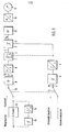
- the device according to FIG. 1 contains, as essential assemblies, an analog divider for forming an output pulse U a , the pulse duty factor of which is a measure of the quotient.
- This analog divider comprises a capacitor 1 and an electronic switch 2 connected in parallel therewith.
- the capacitor voltage is applied to a hysteresis switch 3.
- the hysteresis switch is not only controllable by the capacitor voltage at its input 4, but also has a second control input 5 for resetting.
- the electronic switch 2 and the hysteresis switch 3 - second control input - can be controlled by reshaped volume pulses, which are generated from a pulse shaper by a second hysteresis switch 6 and a monostable multivibrator 7.
- the capacitor 1 of the divider can be charged by a current which is formed from a voltage / current converter 8.
- This voltage / current converter is connected via a low-pass filter 9 to a first changeover switch 10, which is coupled to a second changeover switch 11. In the illustrated switching position of the switch 10, this connects an electronic tachometer 12, on which a voltage analogous to the speed, can be tapped, with the low-pass filter 9.
- path impulses can be converted into pulses of constant pulse length via a frequency / voltage converter with the hysteresis switch 13 and the monostable multivibrator 14, so that the voltage fed into the low-pass filter via the switch 10 also averages the speed traveled is analog.
- the switch position shown of the first switch 10 is assigned a switch position of the second switch 11, in which volume pulses, which are supplied by a flow transmitter, are fed into the device.
- the output pulse Ua is fed into the moving-coil instrument 17 as a mean current value via a second low-pass filter 15 and a second voltage / current converter 16.
- the quotient is formed by the described device:
- the pulse duty factor from which the display of the moving-coil instrument 17 is derived is thus proportional to the fuel volume consumed per distance traveled.
- the described device can also be used to display the speed of a motor, the speed pulses of which are fed into the terminal 19 as variable y.
- the value x is formed as a fixed value at the terminal 18 from a fixed voltage.
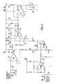
- the volume pulses are fed via the terminal 19, a resistor capacitor combination 39, 40 into the hysteresis switch, which is essentially formed with the differential amplifier 41, which is connected in practically the same way as the differential amplifier 27.
- the output variable of the differential amplifier 41 is fed via a coupling capacitor 42 into the monostable multivibrator, which consists of the differential amplifier 46 connected with resistors 43, 44, 45 in accordance with FIG.
- the formed in the monostable multivibrator are forwarded via the resistor 47 to control the transistor 26 as an electronic switch and to control the hysteresis switch via the additional control input 5.
Landscapes
- Engineering & Computer Science (AREA)
- Physics & Mathematics (AREA)
- Computer Hardware Design (AREA)
- General Physics & Mathematics (AREA)
- Theoretical Computer Science (AREA)
- Mathematical Physics (AREA)
- Fluid Mechanics (AREA)
- Indicating Measured Values (AREA)
- Measuring Volume Flow (AREA)
Applications Claiming Priority (2)
| Application Number | Priority Date | Filing Date | Title |
|---|---|---|---|
| DE19803037417 DE3037417A1 (de) | 1980-10-03 | 1980-10-03 | Einrichtung zur ermittlung des wegspezifischen kraftstoffverbrauchs |
| DE3037417 | 1980-10-03 |
Publications (3)
| Publication Number | Publication Date |
|---|---|
| EP0049335A2 true EP0049335A2 (fr) | 1982-04-14 |
| EP0049335A3 EP0049335A3 (en) | 1984-05-09 |
| EP0049335B1 EP0049335B1 (fr) | 1986-09-03 |
Family
ID=6113532
Family Applications (1)
| Application Number | Title | Priority Date | Filing Date |
|---|---|---|---|
| EP19810105665 Expired EP0049335B1 (fr) | 1980-10-03 | 1981-07-20 | Dispositif de détermination de consommation routière spécifique de carburant |
Country Status (3)
| Country | Link |
|---|---|
| EP (1) | EP0049335B1 (fr) |
| AU (1) | AU7544881A (fr) |
| DE (1) | DE3037417A1 (fr) |
Cited By (1)
| Publication number | Priority date | Publication date | Assignee | Title |
|---|---|---|---|---|
| AU574550B2 (en) * | 1985-01-10 | 1988-07-07 | Bayer Aktiengesellschaft | 6,7-disubstituted-1-cyclopropyl-1,4-dihydro-4-oxo-1,8- naphthyridine-3-carboxylic acids and intermediates |
Families Citing this family (1)
| Publication number | Priority date | Publication date | Assignee | Title |
|---|---|---|---|---|
| WO2018061162A1 (fr) * | 2016-09-29 | 2018-04-05 | 三菱電機株式会社 | Système d'estimation de consommation de carburant, procédé d'estimation de consommation de carburant et programme d'estimation de consommation de carburant |
Family Cites Families (1)
| Publication number | Priority date | Publication date | Assignee | Title |
|---|---|---|---|---|
| US4157030A (en) * | 1978-02-27 | 1979-06-05 | The Bendix Corporation | System for deriving fuel consumption of a vehicle |
-
1980
- 1980-10-03 DE DE19803037417 patent/DE3037417A1/de not_active Withdrawn
-
1981
- 1981-07-20 EP EP19810105665 patent/EP0049335B1/fr not_active Expired
- 1981-09-17 AU AU75448/81A patent/AU7544881A/en not_active Abandoned
Cited By (1)
| Publication number | Priority date | Publication date | Assignee | Title |
|---|---|---|---|---|
| AU574550B2 (en) * | 1985-01-10 | 1988-07-07 | Bayer Aktiengesellschaft | 6,7-disubstituted-1-cyclopropyl-1,4-dihydro-4-oxo-1,8- naphthyridine-3-carboxylic acids and intermediates |
Also Published As
| Publication number | Publication date |
|---|---|
| EP0049335B1 (fr) | 1986-09-03 |
| AU7544881A (en) | 1982-04-08 |
| DE3037417A1 (de) | 1982-05-06 |
| EP0049335A3 (en) | 1984-05-09 |
Similar Documents
| Publication | Publication Date | Title |
|---|---|---|
| DE1900138C2 (de) | Antiblockierregelsystem für ein Fahrzeug, insbesondere Kraftfahrzeug | |
| DE2347729A1 (de) | Elektronische kraftstoff-einspritzeinrichtung | |
| DE2131536A1 (de) | Radschlupfbegrenzer fuer ein angetriebenes Rad eines Kraftfahrzeuges | |
| DE1945420C3 (de) | Digitales Integrations-Synchronisations-Schaltnetzwerk | |
| DE2354839C2 (de) | Elektrisches Meßgerät zur kapazitiven Messung physikalischer Größen | |
| DE2120193A1 (de) | Digitale Schlupffrequenzregelschaltung für eine umrichtergespeiste Asynchronmaschine | |
| DE4308031C2 (de) | Vorrichtung zum Erfassen der Bewegung eines bewegbaren Teils | |
| DE3226073C2 (de) | Vorrichtung zum Erzeugen einer drehzahlabhängigen Signalfolge | |
| EP0049335B1 (fr) | Dispositif de détermination de consommation routière spécifique de carburant | |
| DE19612597A1 (de) | Anschlags- und Blockiererkennung bei einem Schrittmotor | |
| DE2701575C2 (de) | Frequenzwandler für Geschwindigkeits- und Streckenzählgeräte | |
| DE2814768A1 (de) | Geschwindigkeitssteuereinrichtung fuer einen gleichstrommotor | |
| DE2627715C2 (de) | Einrichtung zum Überwachen der Wirtschaftlichkeit des Betriebs einer Kraftfahrzeug-Brennkraftmaschine | |
| DE2163808A1 (de) | Anordnung zum messen des drehmoments von brennkraft-motoren | |
| DE2106916C3 (de) | Induktiver Meßumformer zur Umformung einer mechanischen Auslenkung in eine dazu proportionale elektrische Größe | |
| EP0021340A2 (fr) | Appareil pour la mesure et l'évaluation de valeurs de pointe d'un signal de tnesion pulsant | |
| DE2648021A1 (de) | Elektronisches mess- und zaehlsystem, insbesondere fuer fahrtschreiber | |
| DE2516624C3 (de) | Elektrische Schaltungsanordnung zur Drehzahl- oder Geschwindigkeitsmessung | |
| DE2725618C3 (de) | Vorrichtung zur Messung des Integrals einer zeitabhängigen physikalischen Größe | |
| DE3006011C2 (fr) | ||
| EP0279352A2 (fr) | Circuit d'amplification et de façonnage d'un signal de tension alternative | |
| DE2231513A1 (de) | Anordnung zur beruehrungslosen drehzahlmessung | |
| DE2342480C3 (de) | Einrichtung zur Messung von Frequenzänderungen und Frequenzen | |
| DE1910102A1 (de) | Signalumsetzer | |
| DE2231165A1 (de) | Anordnung zur gewinnung eines elektrischen signals |
Legal Events
| Date | Code | Title | Description |
|---|---|---|---|
| PUAI | Public reference made under article 153(3) epc to a published international application that has entered the european phase |
Free format text: ORIGINAL CODE: 0009012 |
|
| AK | Designated contracting states |
Designated state(s): FR GB IT SE |
|
| 17P | Request for examination filed |
Effective date: 19820421 |
|
| PUAL | Search report despatched |
Free format text: ORIGINAL CODE: 0009013 |
|
| AK | Designated contracting states |
Designated state(s): FR GB IT SE |
|
| GRAA | (expected) grant |
Free format text: ORIGINAL CODE: 0009210 |
|
| AK | Designated contracting states |
Kind code of ref document: B1 Designated state(s): FR GB IT SE |
|
| ET | Fr: translation filed | ||
| ITF | It: translation for a ep patent filed | ||
| PLBE | No opposition filed within time limit |
Free format text: ORIGINAL CODE: 0009261 |
|
| STAA | Information on the status of an ep patent application or granted ep patent |
Free format text: STATUS: NO OPPOSITION FILED WITHIN TIME LIMIT |
|
| PG25 | Lapsed in a contracting state [announced via postgrant information from national office to epo] |
Ref country code: SE Effective date: 19870721 |
|
| 26N | No opposition filed | ||
| PG25 | Lapsed in a contracting state [announced via postgrant information from national office to epo] |
Ref country code: FR Free format text: LAPSE BECAUSE OF NON-PAYMENT OF DUE FEES Effective date: 19880331 |
|
| GBPC | Gb: european patent ceased through non-payment of renewal fee | ||
| REG | Reference to a national code |
Ref country code: FR Ref legal event code: ST |
|
| PG25 | Lapsed in a contracting state [announced via postgrant information from national office to epo] |
Ref country code: GB Free format text: LAPSE BECAUSE OF NON-PAYMENT OF DUE FEES Effective date: 19881118 |
|
| EUG | Se: european patent has lapsed |
Ref document number: 81105665.4 Effective date: 19880831 |