EP0049335A2 - Device for determining the road-specific fuel consumption - Google Patents
Device for determining the road-specific fuel consumption Download PDFInfo
- Publication number
- EP0049335A2 EP0049335A2 EP81105665A EP81105665A EP0049335A2 EP 0049335 A2 EP0049335 A2 EP 0049335A2 EP 81105665 A EP81105665 A EP 81105665A EP 81105665 A EP81105665 A EP 81105665A EP 0049335 A2 EP0049335 A2 EP 0049335A2
- Authority
- EP
- European Patent Office
- Prior art keywords
- switch
- speed
- pulse
- pulses
- hysteresis
- Prior art date
- Legal status (The legal status is an assumption and is not a legal conclusion. Google has not performed a legal analysis and makes no representation as to the accuracy of the status listed.)
- Granted
Links
Images
Classifications
-
- G—PHYSICS
- G01—MEASURING; TESTING
- G01F—MEASURING VOLUME, VOLUME FLOW, MASS FLOW OR LIQUID LEVEL; METERING BY VOLUME
- G01F9/00—Measuring volume flow relative to another variable, e.g. of liquid fuel for an engine
- G01F9/008—Measuring volume flow relative to another variable, e.g. of liquid fuel for an engine where the other variable is the flight or running time
-
- G—PHYSICS
- G06—COMPUTING; CALCULATING OR COUNTING
- G06G—ANALOGUE COMPUTERS
- G06G7/00—Devices in which the computing operation is performed by varying electric or magnetic quantities
- G06G7/48—Analogue computers for specific processes, systems or devices, e.g. simulators
- G06G7/70—Analogue computers for specific processes, systems or devices, e.g. simulators for vehicles, e.g. to determine permissible loading of ships, centre of gravity, necessary fuel
Definitions
- the invention relates to a device for electronically determining the path-specific fuel consumption of a vehicle, in particular a motor vehicle, from volume pulses, the pulse frequency of which corresponds to the fuel flow, and an electrical variable analogous to the speed of the vehicle.
- the volume pulses In such known devices, the volume pulses, the pulse frequency of which is a measure of the flow of fuel through a line, are determined and related to a path-dependent or speed-dependent variable in order to arrive at the consumption expressed in liters per 100 kilometers.
- the . Computing devices required for this are often still relatively complex because of the digital modules and components used, so that their standard introduction into automotive technology is not readily possible, although consumption monitoring is generally desirable.
- the route-specific fuel consumption can vary within wide limits.
- the route-specific fuel consumption takes on very large values for low vehicle speeds; when the vehicle is stationary and the engine is running, this value approaches infinity.
- the object of the present invention is therefore to design a device of the type mentioned at the beginning for the electronic determination of the path-specific fuel consumption in such a way that it uses non-expensive electronic means with high accuracy - within reasonable limits - and in particular no false or misleading values indicates with very large path-specific fuel consumption.
- the value range of the output pulse of the analog divider used according to the invention can be between zero and a maximum value of almost 100%, which is expressed by the pulse duty factor of the output pulse - pulse width to period.
- the circuit arrangement provided according to the invention ensures that when the input variables are exceeded in the device for determining the path-specific consumption, which in itself should have a duty cycle greater than 100%, this duty cycle remains limited to the maximum value. This condition is not easily met with normal dividers. In the device according to the invention, this is done in particular by controlling the hysteresis switch achieved by the volume pulses in such a way that after each volume pulse each output pulse of the Ilysteresis switch assumes a predetermined value, namely, for example, a low signal.
- the device can be designed in such a way that it displays the consumption very precisely in a preferred consumption range, since there is no need to take into account that a completely wrong display of the consumption can take place outside this preferred range, since here the displayed consumption in this case cannot deviate from an upper limit.
- the device is characterized by a relatively low outlay on assemblies and components, since in particular an analog / digital converter or a digital / analog converter can be dispensed with in the divider.
- the device according to the invention is advantageously further developed by a monostable multivibrator for transforming the travel pulses that are fed into the electronic switch and the hysteresis switch. This ensures precise control of these switches regardless of the curve shape of the path pulses.
- the device is advantageously further designed with the features that the capacitor is supplied with current via a voltage / current converter and a low-pass filter connected upstream thereof, which current is proportional to the voltage value dropping on an electronic tachometer. - Since this voltage value is already adapted to the travel speed of the encoder of the travel pulses and the motor vehicle, further means for adapting to the travel speed can be omitted in the device for determining the fuel consumption.
- the speed-analog voltage value can be obtained from the displacement pulses by means of a frequency-voltage converter that can be adjusted to adapt the displacement speed.
- the output pulse at the hysteresis switch of the analog divider is expediently fed to a moving coil instrument as a display device for the consumption via a low-pass filter and a voltage / current converter.
- the output pulse is expediently converted into an average current value which feeds a moving-coil measuring mechanism placed thereon.
- the inertia of the moving-coil measuring unit can also be used directly for averaging.
- the device can also be used optionally to display a speed of the drive machine of the motor vehicle, so that the speed monitoring is practically possible without additional effort, since the modules and components that are provided for consumption monitoring, with minor additions, also for speed monitoring can be shared: The means specified for this are specified in claim 5.
- the input of the analog divider forming the numerator is now subjected to speed pulses instead of the volume pulses and that the input of the analog divider forming the denominator is subjected to a fixed value instead of a voltage value proportional to the speed.
- a fixed value instead of a voltage value proportional to the speed.
- the fixed value still suitably set for the operation of four-cylinder engines and six-cylinder engines, so that one type of device is suitable for a variety of vehicle types by simple adaptation. Consumption and speed can also be displayed by the same moving-coil measuring mechanism, on which corresponding graduations are provided.
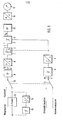
- the device according to FIG. 1 contains, as essential assemblies, an analog divider for forming an output pulse U a , the pulse duty factor of which is a measure of the quotient.
- This analog divider comprises a capacitor 1 and an electronic switch 2 connected in parallel therewith.
- the capacitor voltage is applied to a hysteresis switch 3.
- the hysteresis switch is not only controllable by the capacitor voltage at its input 4, but also has a second control input 5 for resetting.
- the electronic switch 2 and the hysteresis switch 3 - second control input - can be controlled by reshaped volume pulses, which are generated from a pulse shaper by a second hysteresis switch 6 and a monostable multivibrator 7.
- the capacitor 1 of the divider can be charged by a current which is formed from a voltage / current converter 8.
- This voltage / current converter is connected via a low-pass filter 9 to a first changeover switch 10, which is coupled to a second changeover switch 11. In the illustrated switching position of the switch 10, this connects an electronic tachometer 12, on which a voltage analogous to the speed, can be tapped, with the low-pass filter 9.
- path impulses can be converted into pulses of constant pulse length via a frequency / voltage converter with the hysteresis switch 13 and the monostable multivibrator 14, so that the voltage fed into the low-pass filter via the switch 10 also averages the speed traveled is analog.
- the switch position shown of the first switch 10 is assigned a switch position of the second switch 11, in which volume pulses, which are supplied by a flow transmitter, are fed into the device.
- the output pulse Ua is fed into the moving-coil instrument 17 as a mean current value via a second low-pass filter 15 and a second voltage / current converter 16.
- the quotient is formed by the described device:
- the pulse duty factor from which the display of the moving-coil instrument 17 is derived is thus proportional to the fuel volume consumed per distance traveled.
- the described device can also be used to display the speed of a motor, the speed pulses of which are fed into the terminal 19 as variable y.
- the value x is formed as a fixed value at the terminal 18 from a fixed voltage.
- the volume pulses are fed via the terminal 19, a resistor capacitor combination 39, 40 into the hysteresis switch, which is essentially formed with the differential amplifier 41, which is connected in practically the same way as the differential amplifier 27.
- the output variable of the differential amplifier 41 is fed via a coupling capacitor 42 into the monostable multivibrator, which consists of the differential amplifier 46 connected with resistors 43, 44, 45 in accordance with FIG.
- the formed in the monostable multivibrator are forwarded via the resistor 47 to control the transistor 26 as an electronic switch and to control the hysteresis switch via the additional control input 5.
Landscapes
- Physics & Mathematics (AREA)
- Engineering & Computer Science (AREA)
- General Physics & Mathematics (AREA)
- Computer Hardware Design (AREA)
- Theoretical Computer Science (AREA)
- Fluid Mechanics (AREA)
- Mathematical Physics (AREA)
- Indicating Measured Values (AREA)
- Measuring Volume Flow (AREA)
Abstract
Description
Die Erfindung betrifft eine Einrichtung zur elektronischen Ermittlung des wegspezifischen Kraftstoffverbrauchs eines Fahrzeugs, insbesondere eines Kraftfahrzeugs, aus Volumenimpulsen, deren Pulsfrequenz dem Kraftstoffdurchfluß entspricht, und einer elektrischen Größe analog der Geschwindigkeit des Fahrzeugs.The invention relates to a device for electronically determining the path-specific fuel consumption of a vehicle, in particular a motor vehicle, from volume pulses, the pulse frequency of which corresponds to the fuel flow, and an electrical variable analogous to the speed of the vehicle.
Bei derartigen bekannten Einrichtungen werden die Volumenimpulse, deren Pulsfrequenz ein Maß für den Durchfluß des Kraftstoffs durch eine Leitung ist, ermittelt und mit einer weg- oder geschwindigkeitsabhängigen Größe in Beziehung gesetzt, um auf den Verbrauch ausgedrückt in Liter pro 100 Kilometer zu gelangen. Die . hierzu benötigten Recheneinrichtungen sind häufig wegen der verwendeten Digitalbaugruppen und -bauelemente noch verhältnismäßig aufwendig, so daß ihre serienmäßige Einführung in die°Kraftfahrzeugtechnik nicht ohne weiteres möglich ist obwohl eine Verbrauchsüberwachung generell wünschenswert ist.In such known devices, the volume pulses, the pulse frequency of which is a measure of the flow of fuel through a line, are determined and related to a path-dependent or speed-dependent variable in order to arrive at the consumption expressed in liters per 100 kilometers. The . Computing devices required for this are often still relatively complex because of the digital modules and components used, so that their standard introduction into automotive technology is not readily possible, although consumption monitoring is generally desirable.
Bei einer weniger aufwendigen Einrichtung zur Ermittlung des wegspezifischen Kraftstoffverbrauchs, die trotzdem genau arbeiten soll, tritt insbesondere das Problem auf, daß der wegspezifische Kraftstoffverbrauch in weiten Grenzen variieren kann. Insbesondere nimmt der wegspezifische Kraftstoffverbrauch für kleine Fahrzeuggeschwindigkeiten sehr große Werte an, bei stillstehendem Fahrzeug und laufendem Motor geht dieser Wert gegen unendlich.In a less complex device for determining the path-specific fuel consumption, which is nevertheless intended to work precisely, the problem arises in particular, that the route-specific fuel consumption can vary within wide limits. In particular, the route-specific fuel consumption takes on very large values for low vehicle speeds; when the vehicle is stationary and the engine is running, this value approaches infinity.
Zu der vorliegenden Erfindung gehört daher die Aufgabe, eine Einrichtung-der eingangs genannten Gattung zur elektronischen Ermittlung des wegspezifischen Kraftstoffverbrauchs so auszubilden, daß sie unter Einsatz wenig aufwendiger elektronischer Mittel gleichwohl mit - in sinnvollen Grenzen - hoher Genauigkeit arbeitet und insbesondere keine falschen oder irreführenden Werte bei sehr großen wegspezifischen Kraftstoffverbrauchen anzeigt.The object of the present invention is therefore to design a device of the type mentioned at the beginning for the electronic determination of the path-specific fuel consumption in such a way that it uses non-expensive electronic means with high accuracy - within reasonable limits - and in particular no false or misleading values indicates with very large path-specific fuel consumption.
Diese Aufgabe wird durch die Ausbildung der Einrichtung mit den in dem kennzeichnenden Teil des Anspruchs 1 angegebenen Merkmalen gelöst.This object is achieved by the formation of the device with the features specified in the characterizing part of
Der Wertebereich des Ausgangspulses des erfindungsgemäß eingesetzten Analogdividierers kann zwischen Null und einem Maximalwert von nahezu 100 % liegen, der sich durch das Tastverhältnis des Ausgangspulses - Pulsbreite zu Periodendauer - ausdrückt. In besonders vorteilhafter Weise wird mit der erfindungsgemäß vorgesehenen Schaltungsanordnung dafür gesorgt, daß bei Überschreitung der Eingangsgrößen in die Einrichtung zur Ermittlung des wegspezifischen Verbrauchs,die an sich ein Tastverhältnis größer als 100 % zur Folge haben müßte, dieses Tastverhältnis auf den Maximalwert begrenzt bleibt. Diese Bedingung ist bei normalen Dividierern nicht ohne weiteres erfüllt. Bei der erfindungsgemäßen Einrichtung wird dies insbesondere durch die Steuerung des Hysteresisschalters durch die Volumenimpulse in der Weise erreicht, daß nach jedem Volumenimpuls jeder Ausgangsimpuls des Ilysteresisschalters einen vorgegebenen Wert annimmt, nämlich beispielsweise ein Low-Signal.The value range of the output pulse of the analog divider used according to the invention can be between zero and a maximum value of almost 100%, which is expressed by the pulse duty factor of the output pulse - pulse width to period. In a particularly advantageous manner, the circuit arrangement provided according to the invention ensures that when the input variables are exceeded in the device for determining the path-specific consumption, which in itself should have a duty cycle greater than 100%, this duty cycle remains limited to the maximum value. This condition is not easily met with normal dividers. In the device according to the invention, this is done in particular by controlling the hysteresis switch achieved by the volume pulses in such a way that after each volume pulse each output pulse of the Ilysteresis switch assumes a predetermined value, namely, for example, a low signal.
Dadurch kann die Einrichtung so ausgebildet werden, daß sie in einem bevorzugten Verbrauchsbereich den Verbrauch sehr genau anzeigt, da keine Rücksicht darauf genommen werden muß, daß außerhalb dieses bevorzugten Bereichs eine völlig falsche Anzeige des Verbrauchs erfolgen kann, da hier der angezeigte Verbrauch in diesem Fall von einem obersten Grenzwert nicht abweichen kann. Darüber hinaus zeichnet sich die Einrichtung durch einen verhältnismäßig geringen Aufwand an Baugruppen und Bauelementen aus, da insbesondere auf einen Analog/Digitalumsetzer oder einen Digital/Analogumsetzer in dem Dividierer verzichtet werden kann.As a result, the device can be designed in such a way that it displays the consumption very precisely in a preferred consumption range, since there is no need to take into account that a completely wrong display of the consumption can take place outside this preferred range, since here the displayed consumption in this case cannot deviate from an upper limit. In addition, the device is characterized by a relatively low outlay on assemblies and components, since in particular an analog / digital converter or a digital / analog converter can be dispensed with in the divider.
Die erfindungsgemäße Einrichtung ist vorteilhaft weitergebildet durch eine monostabile Kippstufe zur Umformung der Wegimpulse, die in den elektronischen Schalter und den Hysteresisschalter eingespeist werden. Dadurch wird eine genaue Steuerung dieser Schalter unabhängig von der Kurvenform der Wegimpulse gewährleistet.The device according to the invention is advantageously further developed by a monostable multivibrator for transforming the travel pulses that are fed into the electronic switch and the hysteresis switch. This ensures precise control of these switches regardless of the curve shape of the path pulses.
Vorteilhaft ist die Einrichtung weiter mit den Merkmalen ausgebildet, daß der Kondensator über einen Spannungs/ Stromwandler und einen diesem vorgeschalteten Tiefpaß mit Strom beaufschlagt wird, der dem an einem elektronischen Tachometer abfallenden Spannungswert proportional ist. - Da dieser Spannungswert bereits an die Wegdrehzahl des Gebers der Wegimpulse und des Kraftfahrzeugs angepaßt ist, können in der Einrichtung zur Ermittlung des Kraftstoffverbrauchs weitere Mittel zur Anpassung an die Wegdrehzahl entfallen.The device is advantageously further designed with the features that the capacitor is supplied with current via a voltage / current converter and a low-pass filter connected upstream thereof, which current is proportional to the voltage value dropping on an electronic tachometer. - Since this voltage value is already adapted to the travel speed of the encoder of the travel pulses and the motor vehicle, further means for adapting to the travel speed can be omitted in the device for determining the fuel consumption.
Wird hingegen kein elektronischer Tachometer vorgesehen, so kann der geschwindigkeitsanaloge Spannungswert aus den Wegimpulsen durch einen zur Wegdrehzahlanpassung einstellbaren Frequenzspannungswandler gewonnen werden.If, on the other hand, no electronic tachometer is provided, the speed-analog voltage value can be obtained from the displacement pulses by means of a frequency-voltage converter that can be adjusted to adapt the displacement speed.
Der Ausgangspuls an dem Hysteresisschalter des Analogdividierers wird zweckmäßig über einen Tiefpaß und einen Spannungs/Stromwandler einem Drehspulinstrument als Anzeigeeinrichtung des Verbrauchs zugeführt. - Damit erfolgt in zweckmäßiger Weise eine Umformung des Ausgangspulses in einen Strommittelwert, der ein hierauf abgestelltes Drehspulmeßwerk speist. - Anstelle des Tiefpasses kann auch die Trägheit des Drehspulmeßwerks direkt zur Mittelwertbildung ausgenutzt werden.The output pulse at the hysteresis switch of the analog divider is expediently fed to a moving coil instrument as a display device for the consumption via a low-pass filter and a voltage / current converter. In this way, the output pulse is expediently converted into an average current value which feeds a moving-coil measuring mechanism placed thereon. - Instead of the low-pass filter, the inertia of the moving-coil measuring unit can also be used directly for averaging.
In besonders geschickter Weise kann die Einrichtung auch wahlweise zur Anzeige einer Drehzahl der Antriebsmaschine des Kraftfahrzeugs verwendet werden, so daß die Drehzahlüberwachung praktisch ohne zusätzlichen Aufwand möglich ist, da sich die Baugruppen und Bauelemente, die zur Verbrauchsüberwachung vorgesehen sind, mit geringfügigen Zusätzen auch zur Drehzahlüberwachung mitbenutzen lassen: Die hierzu angegebenen Mittel sind in dem Patentanspruch 5 angegeben.In a particularly clever manner, the device can also be used optionally to display a speed of the drive machine of the motor vehicle, so that the speed monitoring is practically possible without additional effort, since the modules and components that are provided for consumption monitoring, with minor additions, also for speed monitoring can be shared: The means specified for this are specified in
Wesentlich bei der Mehrfachverwendung der Einrichtung ist, daß der den Zähler bildende Eingang des Analogdividierers anstelle der Volumenimpulse nun mit Drehzahlimpulsen beaufschlagt wird und daß der den Nenner bildende Eingang des Analogdividierers mit einem Festwert anstelle eines geschwindigkeitsproportionalen Spannungswerts beaufschlagt wird. Je nach der Schaltstellung eines Zweifachumschalters kann somit zwischen Drehzahlanzeige und Verbrauchsanzeige gewählt werden. Zusätzlich läßt sich der Festwert noch in zweckmäßiger Weise für den Betrieb von Vierzylindermotoren und Sechszylindermotoren einstellen, so daß ein Typ der Einrichtung durch einfache Anpassung für eine Vielzahl von Fahrzeugtypen geeignet wird. Verbrauch und Drehzahl können dabei auch durch dasselbe Drehspulmeßwerk angezeigt werden, auf dem entsprechende Skalenteilungen vorgesehen sind.It is essential for the multiple use of the device that the input of the analog divider forming the numerator is now subjected to speed pulses instead of the volume pulses and that the input of the analog divider forming the denominator is subjected to a fixed value instead of a voltage value proportional to the speed. Depending on the switching position of a double changeover switch, you can choose between speed display and consumption display. In addition, the fixed value still suitably set for the operation of four-cylinder engines and six-cylinder engines, so that one type of device is suitable for a variety of vehicle types by simple adaptation. Consumption and speed can also be displayed by the same moving-coil measuring mechanism, on which corresponding graduations are provided.
Die Erfindung wird im folgenden an Hand einer Zeichnung mit 3 Figuren erläutert. Es zeigen:
Figur 1 ein Blockschaltbild der Einrichtung zur Ermittlung des wegspezifischen Kraftstoffverbrauchs und der Drehzahl;- Figur 2 Impulsdiagramme wesentlicher Größen in der Einrichtung nach
Figur 1 und - Figur 3 ein detaillierteres Ausführungsbeispiel der Einrichtung nach
Figur 1 mit Ausnahme der Elemente zur Drehzahlanzeige.
- Figure 1 is a block diagram of the device for determining the path-specific fuel consumption and speed;
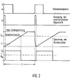
- Figure 2 pulse diagrams of essential quantities in the device of Figure 1 and
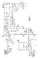
- Figure 3 shows a more detailed embodiment of the device of Figure 1 with the exception of the elements for speed display.
Die Einrichtung nach Figur 1 enthält als wesentliche Baugruppen einen Analog-Dividierer zur Bildung eines Ausgangspulses Ua, dessen Tastverhältnis ein Maß für den Quotienten ist. Dieser Analog-Dividierer umfaßt einen Kondensator 1 und einen diesem parallel geschalteten elektronischen Schalter 2. Mit der Kondensatorspannung wird ein Hysteresisschalter 3 beaufschlagt. Der Hysteresisschalter ist nicht nur durch die Kondensatorspannung an seinem Eingang 4 steuerbar, sondern weist einen zweiten Steuereingang 5 zur Rückstellung auf. Der elektronische Schalter 2 und der Hysteresisschalter 3 - zweiter Steuereingang - sind durch umgeformte Volumenimpulse steuerbar, die aus einem Pulsformer gebildet durch einen zweiten Hysteresisschalter 6 und eine monostabile Kippstufe 7 erzeugt werden.The device according to FIG. 1 contains, as essential assemblies, an analog divider for forming an output pulse U a , the pulse duty factor of which is a measure of the quotient. This analog divider comprises a
Der Kondensator 1 des Dividierers ist durch einen Strom aufladbar, der aus einem Spannungs/Stromwandler 8 gebildet wird. Dieser Spannungs/Stromwandler steht über einen Tiefpaß 9 mit einem ersten Umschalter 10 in Verbindung, der mit einem zweiten Umschalter 11 gekuppelt ist. In der gezeichneten Schaltstellung des Umschalters 10 verbindet dieser einen elektronischen Tachometer 12, an dem eine der Geschwindigkeit analoge Spannung abgreifbar ist, mit dem Tiefpaß 9.The
Ist kein elektronischer Tachometer 12 vorhanden, so können .Wegimpulse über einen Frequenz/Spannungswandler mit dem Hysteresisschalter 13 und der monostabilen Kippstufe 14 in Impulse konstanter Impulslänge umgewandelt werden, so daß die über den Umschalter 10 in den Tiefpaß eingespeiste Spannung im Mittelwert ebenfalls der gefahrenen Geschwindigkeit analog ist.If there is no
Der eingezeichneten Schaltstellung des ersten Umschalters 10 ist eine Schaltstellung des zweiten Umschalters 11 zugeordnet, in der Volumenimpulse, die von einem Durchflußgeber geliefert werden, in die Einrichtung eingespeist werden.The switch position shown of the
Zur Anzeige des wegspezifischen Kraftstoffverbrauchs wird der Ausgangspuls Ua über einen zweiten Tiefpaß 15 und einen zweiten Spannungs/Stromwandler 16 als Strommittelwert in das Drehspulinstrument 17 eingespeist.To display the path-specific fuel consumption, the output pulse Ua is fed into the moving-
Die Einrichtung nach Figur 1 bildet den wegspezifischen Kraftstoffverbrauch in folgender, unter Hinzunahme der Figur 2 zu erläuternder Weise, so daß der Quotient der Pulsfrequenz y der Volumenimpulse an einer Klemme 19 als Zähler und der geschwindigkeitsanalogen Spannung x an der Klemme 18 als Nenner gebildet wird:
- Zum Zeitpunkt Null wird durch eine Vorderflanke eines Volumenimpulses - Impuls a - ein Impuls b am Ausgang der monostabilen Kippstufe 7 abgeleitet, der über den Schalter 2 den
Kondensator 1 entladen läßt, so daß die Kondensatorspannung c zunächst Null ist. Der Ausgangspuls Uades Hysteresisschalter 3 befindet sich dann auf Low-Potential. Nach Verschwinden des umgeformten Impulses b wird der Kondensator durch einen Ladestrom aufgeladen, welcher der geschwindigkeitsanalogen Spannung x an derKlemme 18 proportional ist. Damit erreicht die Kondensatorspannung mehr-oder weniger schnell eine Schwellwertspannung Us, bei der der Hysteresisschalter 3 umschaltet. Der Hysteresisschalter erzeugt seinen Ausgangspuls Ua in der Weise, daß er nach Verschwinden des umgeformten Impulses b zunächst ein High-Signal abgibt, welches so lange anhält, bis die Schwellwertspannung Us erreicht wird, um dann auf das Low-Signal bzw. Low-Potential abzufallen. Durch die zusätzliche Steuerung des Hysteresisschalters 3 über denSteuereingang 5 wird erreicht, daß der Ausgangspuls am Ende einer Periode T auch dann verschwindet, wenn die Kondensatorspannung noch nicht den Wert Us erreicht haben sollte, weil die Geschwindigkeit des Fahrzeugs Null oder sehr klein ist. In diesem Fall wird also praktisch das Tastverhältnis 1 - gebildet aus der Dauer eines Impulses U zur Periodendauer T erreicht. Die Periodendauer T ist umgekehrt proportional der Pulsfrequenz der Volumenimpulse.
- At the time zero, a pulse b at the output of the monostable multivibrator 7 is derived by a leading edge of a volume pulse - pulse a - and causes the
capacitor 1 to be discharged via the switch 2, so that the capacitor voltage c is initially zero. The output pulse Uades hysteresis switch 3 is then at low potential. After the transformed pulse b has disappeared, the capacitor is charged by a charging current which is proportional to the speed-analog voltage x at theterminal 18. The capacitor voltage thus more or less quickly reaches a threshold voltage U s at which the hysteresis switch 3 switches. The hysteresis switch generates its output pulse U a in such a way that, after the deformed pulse b has disappeared, it first emits a high signal which continues until the threshold voltage U s is reached and then switches to the low signal or low signal. Potential to drop. The additional control of the hysteresis switch 3 via thecontrol input 5 ensures that the output pulse disappears at the end of a period T even if the capacitor voltage should not yet have reached the value U s because the speed of the vehicle is zero or very low. In this case, the duty cycle 1 - formed from the duration of a pulse U to the period T is practically reached. The period T is inversely proportional to the pulse frequency of the volume pulses.
Durch die beschriebene Einrichtung wird der Quotient gebildet:
Somit ist das Tastverhältnis, aus dem die Anzeige des Drehspulinstruments 17 abgeleitet wird, proportional dem pro gefahrener Wegstrecke verbrauchten Kraftstoffvolumen.The pulse duty factor from which the display of the moving-
In der entgegengesetzten Schaltstellung der Umschalter 10 und 11 kann die beschriebene Einrichtung auch dazu verwendet werden, die Drehzahl eines Motors anzuzeigen, dessen Drehzahlimpulse in die Klemme 19 als Größe y eingespeist werden. Dabei wird der Wert x als Festwert an der Klemme 18 aus einer festen Spannung gebildet.In the opposite switching position of the changeover switches 10 and 11, the described device can also be used to display the speed of a motor, the speed pulses of which are fed into the terminal 19 as variable y. The value x is formed as a fixed value at the terminal 18 from a fixed voltage.
In Figur 3 ist der sich an die Umschalter 10 und 11 zur Bildung des Quotienten der Größen an diesen Umschaltern detaillierter dargestellt, wobei für gleiche Teile übereinstimmende Bezugszeichen verwendet werden:
Der Klemme 18 istein aus Widerständen 20, 21 und einem Kondensator 22 gebildete Kombination als Tiefpaß vorgeschaltet. An dieKlemme 18 schließt sich ein Spannungs/ Stromwandler an, der aus einem gegengekoppelten Differenzverstärker 23mit nachfolgenden Transistor 24 besteht.Der Kondensator 1 ist über einen Widerstand 25 und einenals Transistor 26 ausgebildeten elektronischen Schalter entladbar. Die Kondensatorspannung wird über den Hysteresisschalter überwacht, der ausdem Differenzverstärker 27mit den Widerständen den Widerständen und dem Kondensator 34, zugeführt. Von dort gelangt ein dem Mittelwert des Ausgangspulses U a entsprechender Spannungswert,aufden der Kondensator 34 aufgeladen ist, ineinen Differenzverstärker 35 mitdem nachgeschalteten Transistor 36, wobei diese aktiven Elemente zur Bildung einer gesteuerten Stromquelle gegengekoppelt sind.Das Drehspulinstrument 17 wirdüber den Transistor 36 und einen Vorwiderstand 37 aus der Betriebsspannung UB gespeist. Die Anzeige des Drehspulinstruments ist zusätzlich durch einen Kondensator 38 geglättet.
-
Terminal 18 is connected upstream of a combination ofresistors 20, 21 and a capacitor 22 as a low-pass filter. At the terminal 18 is connected to a voltage / current converter, which consists of a negative feedbackdifferential amplifier 23 withsubsequent transistor 24. Thecapacitor 1 can be discharged via aresistor 25 and an electronic switch designed as atransistor 26. The capacitor voltage is monitored via the hysteresis switch, which is connected from thedifferential amplifier 27 with theresistors resistors capacitor 34. From there, a voltage value corresponding to the mean value of the output pulse U a , to which thecapacitor 34 is charged, reaches adifferential amplifier 35 with thedownstream transistor 36, these active elements being negative-coupled to form a controlled current source. The movingcoil instrument 17 is fed via thetransistor 36 and aseries resistor 37 from the operating voltage U B. The display of the moving coil instrument is additionally smoothed by acapacitor 38.
Die Volumenimpulse werden über die Klemme 19, eine Widerstandskondensatorkombination 39, 40 in den Hysteresisschalter eingespeist, welcher im wesentlichen mit dem Differenzverstärker 41 gebildet ist, der in praktisch gleicher Weise wie der Differenzverstärker 27 geschaltet ist. Die Ausgangsgröße des Differenzverstärkers 41 wird über einen Koppelkondensator 42 in die monostabile Kippstufe eingespeist, die aus dem entsprechend Figur 3 mit Widerständen 43, 44, 45 geschalteten Differenzverstärker 46 besteht. Die in der monostabilen Kippstufe umgeformten Impulse werden über den Widerstand 47 zur Steuerung des Transistors 26 als elektronischem Schalter und zur Steuerung des Hysteresisschalters über den zusätzlichen Steuereingang 5 weitergeleitet.The volume pulses are fed via the terminal 19, a
Claims (5)
gekennzeiohnet durch
einen elektronischen Analog-Dividierer zur Quotientenbildung aus der Pulsfrequenz als Zähler und der geschwindigkeitsanalogen Größe als Nenner, mit den Merkmalen, daß ein Kondensator (1) mit einem der Geschwindigkeit analogen Strom aufladbar ist und durch einen elektronischen, durch die Volumenimpulse gesteuerten Schalter (2) entladbar ist, daß ein Eingang eines Hysteresisschalters (3) mit der Kondensatorspannung beaufschlagbar ist und ein Ausgang des Hysteresisschalters mit einer Anzeigeeinrichtung (Drehspulinstrument 17) in Verbindung steht, daß der Hysteresisschalter ebenfalls durch die Volumenimpulse derart steuerbar ist, daß nach jedem Volumenimpuls jeder Ausgangsimpuls (Ausgangspuls Ua) des Hysteresisschalters einen vorgegebenen Wert annimmt (Low-Signal), so daß das Tastverhältnis des Ausgangspulses bis zu dem Tastverhältnis 1 dem Quotienten proportional ist.1. Device for the electronic determination of the path-specific fuel consumption of a vehicle, in particular a motor vehicle, from volume pulses, the pulse frequency of which corresponds to the fuel flow, and an electrical variable analogous to the speed of the vehicle,
characterized by
an electronic analog divider for forming the quotient from the pulse frequency as a numerator and the speed-analogous value as a denominator, with the features that a capacitor (1) can be charged with a current analogous to the speed and by an electronic switch (2) controlled by the volume pulses It can be discharged that the capacitor voltage can be applied to an input of a hysteresis switch (3) and an output of the hysteresis switch is connected to a display device (moving coil instrument 17) such that the hysteresis switch can also be controlled by the volume pulses in such a way that after each volume pulse each output pulse ( Output pulse U a ) of the hysteresis switch assumes a predetermined value (low signal), so that the pulse duty factor of the output pulse is proportional to the quotient up to the pulse duty factor 1.
gekennzeichnet durch
eine monostabile Kippstufe (7) zur Umformung der Wegimpulse, die in den elektronischen Schalter (2) und den Hysteresisschalter (3) eingespeist werden.2. Device according to claim 1,
marked by
a monostable multivibrator (7) for reshaping the travel pulses, which are fed into the electronic switch (2) and the hysteresis switch (3).
dadurch gekennzeichnet ,
daß der Kondensator (1) über einen Spannungs/Stromwandler (8) und einen diesem vorgeschalteten Tiefpaß (9) mit Strom beaufschlagt wird, der dem an einem elektronischen Tachometer abfallenden Spannungswert proportional ist.3. Device according to claim 1 or 2,
characterized ,
that the capacitor (1) is supplied with current via a voltage / current converter (8) and a low-pass filter (9) connected upstream thereof, which current is proportional to the voltage value dropping on an electronic tachometer.
daß an den Hysteresisschalter (3) über einen Tiefpaß (15) und einen Spannungs/Stromwandler (16) ein Drehspulinstrument (17) als Anzeigeeinrichtung angeschlossen ist.4. Device according to one of claims 1-3, characterized in
that a moving coil instrument (17) is connected to the hysteresis switch (3) via a low-pass filter (15) and a voltage / current converter (16) as a display device.
daß zur wahlweisen Anzeige einer Drehzahl mit der gleichen Anzeigeeinrichtung der steuerbare Schalter (2) und der Hysteresisschalter (3) über einen ersten Umschalter (11) anstatt der Volumenimpulse mit Drehzahlimpulsen steuerbar sind und daß über einen mit dem ersten Umschalter gekuppelten zweiten Umschalter (10) der Kondensator mit einem Festwert-Strom anstatt des geschwindigkeitsanalogen Stroms beaufschlagbar ist.5. Device according to one of claims 1-4, characterized in
that for the optional display of a speed with the same display device, the controllable switch (2) and the hysteresis switch (3) can be controlled via a first switch (11) instead of the volume pulses with speed pulses and that via a second switch (10) coupled to the first switch the capacitor can be supplied with a fixed value current instead of the speed-analog current.
Applications Claiming Priority (2)
| Application Number | Priority Date | Filing Date | Title |
|---|---|---|---|
| DE19803037417 DE3037417A1 (en) | 1980-10-03 | 1980-10-03 | DEVICE FOR DETERMINING THE WAY-SPECIFIC FUEL CONSUMPTION |
| DE3037417 | 1980-10-03 |
Publications (3)
| Publication Number | Publication Date |
|---|---|
| EP0049335A2 true EP0049335A2 (en) | 1982-04-14 |
| EP0049335A3 EP0049335A3 (en) | 1984-05-09 |
| EP0049335B1 EP0049335B1 (en) | 1986-09-03 |
Family
ID=6113532
Family Applications (1)
| Application Number | Title | Priority Date | Filing Date |
|---|---|---|---|
| EP19810105665 Expired EP0049335B1 (en) | 1980-10-03 | 1981-07-20 | Device for determining the road-specific fuel consumption |
Country Status (3)
| Country | Link |
|---|---|
| EP (1) | EP0049335B1 (en) |
| AU (1) | AU7544881A (en) |
| DE (1) | DE3037417A1 (en) |
Cited By (1)
| Publication number | Priority date | Publication date | Assignee | Title |
|---|---|---|---|---|
| AU574550B2 (en) * | 1985-01-10 | 1988-07-07 | Bayer Aktiengesellschaft | 6,7-disubstituted-1-cyclopropyl-1,4-dihydro-4-oxo-1,8- naphthyridine-3-carboxylic acids and intermediates |
Families Citing this family (1)
| Publication number | Priority date | Publication date | Assignee | Title |
|---|---|---|---|---|
| DE112016007166B4 (en) * | 2016-09-29 | 2022-12-15 | Mitsubishi Electric Corporation | Fuel efficiency estimation system, fuel efficiency estimation method and fuel efficiency estimation program |
Citations (1)
| Publication number | Priority date | Publication date | Assignee | Title |
|---|---|---|---|---|
| US4157030A (en) * | 1978-02-27 | 1979-06-05 | The Bendix Corporation | System for deriving fuel consumption of a vehicle |
-
1980
- 1980-10-03 DE DE19803037417 patent/DE3037417A1/en not_active Withdrawn
-
1981
- 1981-07-20 EP EP19810105665 patent/EP0049335B1/en not_active Expired
- 1981-09-17 AU AU75448/81A patent/AU7544881A/en not_active Abandoned
Patent Citations (1)
| Publication number | Priority date | Publication date | Assignee | Title |
|---|---|---|---|---|
| US4157030A (en) * | 1978-02-27 | 1979-06-05 | The Bendix Corporation | System for deriving fuel consumption of a vehicle |
Non-Patent Citations (1)
| Title |
|---|
| CONTROL ENGINEERING, Band 15, Nr. 5, Mai 1968, Seite 64, New York, US; "Simple circuit multiplies analog and digital signals". * |
Cited By (1)
| Publication number | Priority date | Publication date | Assignee | Title |
|---|---|---|---|---|
| AU574550B2 (en) * | 1985-01-10 | 1988-07-07 | Bayer Aktiengesellschaft | 6,7-disubstituted-1-cyclopropyl-1,4-dihydro-4-oxo-1,8- naphthyridine-3-carboxylic acids and intermediates |
Also Published As
| Publication number | Publication date |
|---|---|
| EP0049335B1 (en) | 1986-09-03 |
| DE3037417A1 (en) | 1982-05-06 |
| AU7544881A (en) | 1982-04-08 |
| EP0049335A3 (en) | 1984-05-09 |
Similar Documents
| Publication | Publication Date | Title |
|---|---|---|
| DE2131536A1 (en) | Wheel slip limiter for a driven wheel of a motor vehicle | |
| DE2347729A1 (en) | ELECTRONIC FUEL INJECTION DEVICE | |
| DE1945420C3 (en) | Digital integration synchronization switching network | |
| DE2618970B2 (en) | Speedometer for internal combustion engines | |
| DE2354839C2 (en) | Electrical measuring device for the capacitive measurement of physical quantities | |
| DE4308030C2 (en) | Device for detecting the movement of a moving part | |
| DE2402448A1 (en) | ANALOG SPEED MEASURING DEVICE | |
| DE3226073C2 (en) | Device for generating a speed-dependent signal sequence | |
| DE2942134A1 (en) | EVALUATION FOR AN INDUCTIVE ENCODER | |
| DE2730699A1 (en) | DEVICE FOR DISPLAYING A MECHANICAL MEASURING SIZE, IN PARTICULAR THE SPEED OF A MOTOR VEHICLE | |
| EP0049335B1 (en) | Device for determining the road-specific fuel consumption | |
| DE2701575C2 (en) | Frequency converter for speed and distance counters | |
| DE19612597A1 (en) | Stop and block detection in a stepper motor | |
| DE2627715C2 (en) | Device for monitoring the profitability of the operation of a motor vehicle internal combustion engine | |
| EP0666957B1 (en) | Electromotive drive | |
| DE3247991C2 (en) | Driver circuit for a brushless DC motor with a Hall element | |
| DE2516624C3 (en) | Electrical circuit arrangement for speed or speed measurement | |
| EP0021340A2 (en) | Apparatus for measuring and evaluating the peak values of a pulsatory voltage signal | |
| DE2106916C3 (en) | Inductive transducer for converting a mechanical deflection into an electrical quantity proportional to it | |
| DE2648021A1 (en) | ELECTRONIC MEASURING AND COUNTING SYSTEM, IN PARTICULAR FOR TACHOGRAPH | |
| DE3927966A1 (en) | METHOD AND CIRCUIT ARRANGEMENT FOR GENERATING AN INPUT SIZE FOR A CROSS COIL INDICATOR | |
| DE2531605A1 (en) | DEVICE FOR DETERMINING THE FUEL CONSUMPTION OF A MOTOR VEHICLE | |
| DE2725618C3 (en) | Device for measuring the integral of a time-dependent physical quantity | |
| DE3006011C2 (en) | ||
| DE3604048A1 (en) | Device for electrical indication and limit-value-monitoring of a non-electrical quantity |
Legal Events
| Date | Code | Title | Description |
|---|---|---|---|
| PUAI | Public reference made under article 153(3) epc to a published international application that has entered the european phase |
Free format text: ORIGINAL CODE: 0009012 |
|
| AK | Designated contracting states |
Designated state(s): FR GB IT SE |
|
| 17P | Request for examination filed |
Effective date: 19820421 |
|
| PUAL | Search report despatched |
Free format text: ORIGINAL CODE: 0009013 |
|
| AK | Designated contracting states |
Designated state(s): FR GB IT SE |
|
| GRAA | (expected) grant |
Free format text: ORIGINAL CODE: 0009210 |
|
| AK | Designated contracting states |
Kind code of ref document: B1 Designated state(s): FR GB IT SE |
|
| ET | Fr: translation filed | ||
| ITF | It: translation for a ep patent filed |
Owner name: STUDIO JAUMANN |
|
| PLBE | No opposition filed within time limit |
Free format text: ORIGINAL CODE: 0009261 |
|
| STAA | Information on the status of an ep patent application or granted ep patent |
Free format text: STATUS: NO OPPOSITION FILED WITHIN TIME LIMIT |
|
| PG25 | Lapsed in a contracting state [announced via postgrant information from national office to epo] |
Ref country code: SE Effective date: 19870721 |
|
| 26N | No opposition filed | ||
| PG25 | Lapsed in a contracting state [announced via postgrant information from national office to epo] |
Ref country code: FR Free format text: LAPSE BECAUSE OF NON-PAYMENT OF DUE FEES Effective date: 19880331 |
|
| GBPC | Gb: european patent ceased through non-payment of renewal fee | ||
| REG | Reference to a national code |
Ref country code: FR Ref legal event code: ST |
|
| PG25 | Lapsed in a contracting state [announced via postgrant information from national office to epo] |
Ref country code: GB Free format text: LAPSE BECAUSE OF NON-PAYMENT OF DUE FEES Effective date: 19881118 |
|
| EUG | Se: european patent has lapsed |
Ref document number: 81105665.4 Effective date: 19880831 |