EP0049153A2 - Appareil pour corriger des erreurs de position. - Google Patents
Appareil pour corriger des erreurs de position. Download PDFInfo
- Publication number
- EP0049153A2 EP0049153A2 EP81304485A EP81304485A EP0049153A2 EP 0049153 A2 EP0049153 A2 EP 0049153A2 EP 81304485 A EP81304485 A EP 81304485A EP 81304485 A EP81304485 A EP 81304485A EP 0049153 A2 EP0049153 A2 EP 0049153A2
- Authority
- EP
- European Patent Office
- Prior art keywords
- along
- control
- movable body
- control axis
- axes
- Prior art date
- Legal status (The legal status is an assumption and is not a legal conclusion. Google has not performed a legal analysis and makes no representation as to the accuracy of the status listed.)
- Granted
Links
Images

Classifications
-
- G—PHYSICS
- G05—CONTROLLING; REGULATING
- G05B—CONTROL OR REGULATING SYSTEMS IN GENERAL; FUNCTIONAL ELEMENTS OF SUCH SYSTEMS; MONITORING OR TESTING ARRANGEMENTS FOR SUCH SYSTEMS OR ELEMENTS
- G05B19/00—Programme-control systems
- G05B19/02—Programme-control systems electric
- G05B19/18—Numerical control [NC], i.e. automatically operating machines, in particular machine tools, e.g. in a manufacturing environment, so as to execute positioning, movement or co-ordinated operations by means of programme data in numerical form
- G05B19/19—Numerical control [NC], i.e. automatically operating machines, in particular machine tools, e.g. in a manufacturing environment, so as to execute positioning, movement or co-ordinated operations by means of programme data in numerical form characterised by positioning or contouring control systems, e.g. to control position from one programmed point to another or to control movement along a programmed continuous path
- G05B19/40—Open loop systems, e.g. using stepping motor
-
- G—PHYSICS
- G05—CONTROLLING; REGULATING
- G05B—CONTROL OR REGULATING SYSTEMS IN GENERAL; FUNCTIONAL ELEMENTS OF SUCH SYSTEMS; MONITORING OR TESTING ARRANGEMENTS FOR SUCH SYSTEMS OR ELEMENTS
- G05B19/00—Programme-control systems
- G05B19/02—Programme-control systems electric
- G05B19/18—Numerical control [NC], i.e. automatically operating machines, in particular machine tools, e.g. in a manufacturing environment, so as to execute positioning, movement or co-ordinated operations by means of programme data in numerical form
- G05B19/41—Numerical control [NC], i.e. automatically operating machines, in particular machine tools, e.g. in a manufacturing environment, so as to execute positioning, movement or co-ordinated operations by means of programme data in numerical form characterised by interpolation, e.g. the computation of intermediate points between programmed end points to define the path to be followed and the rate of travel along that path
-
- G—PHYSICS
- G05—CONTROLLING; REGULATING
- G05B—CONTROL OR REGULATING SYSTEMS IN GENERAL; FUNCTIONAL ELEMENTS OF SUCH SYSTEMS; MONITORING OR TESTING ARRANGEMENTS FOR SUCH SYSTEMS OR ELEMENTS
- G05B2219/00—Program-control systems
- G05B2219/30—Nc systems
- G05B2219/41—Servomotor, servo controller till figures
- G05B2219/41036—Position error in memory, lookup table for correction actual position
-
- G—PHYSICS
- G05—CONTROLLING; REGULATING
- G05B—CONTROL OR REGULATING SYSTEMS IN GENERAL; FUNCTIONAL ELEMENTS OF SUCH SYSTEMS; MONITORING OR TESTING ARRANGEMENTS FOR SUCH SYSTEMS OR ELEMENTS
- G05B2219/00—Program-control systems
- G05B2219/30—Nc systems
- G05B2219/41—Servomotor, servo controller till figures
- G05B2219/41055—Kind of compensation such as pitch error compensation
-
- G—PHYSICS
- G05—CONTROLLING; REGULATING
- G05B—CONTROL OR REGULATING SYSTEMS IN GENERAL; FUNCTIONAL ELEMENTS OF SUCH SYSTEMS; MONITORING OR TESTING ARRANGEMENTS FOR SUCH SYSTEMS OR ELEMENTS
- G05B2219/00—Program-control systems
- G05B2219/30—Nc systems
- G05B2219/41—Servomotor, servo controller till figures
- G05B2219/41062—Compensation for two, three axis at the same time, crosscoupling
-
- G—PHYSICS
- G05—CONTROLLING; REGULATING
- G05B—CONTROL OR REGULATING SYSTEMS IN GENERAL; FUNCTIONAL ELEMENTS OF SUCH SYSTEMS; MONITORING OR TESTING ARRANGEMENTS FOR SUCH SYSTEMS OR ELEMENTS
- G05B2219/00—Program-control systems
- G05B2219/30—Nc systems
- G05B2219/49—Nc machine tool, till multiple
- G05B2219/49196—Screw
Definitions
- This invention relates to a method/for correcting a for example but not exclusively, positional error, in a numerical control device of the type usedto control a machine tool.
- a numerical control device When controlling the feed of a workpiece table in a machine tool such as a lathe, positional errors stemming from such mechanical phenomena as pitch error and backlash can occur.
- a numerical control device ordinarily is furnished with pitch error and backlash correction functions that the numerical control device relies upon to correct positional errors when controlling a machine tool.
- pitch error and backlash correction functions that the numerical control device relies upon to correct positional errors when controlling a machine tool.
- the body may, for example, be capable of movement along the X and Y axes.
- the range of movement along each axis is divided into a plurality of segments.
- a characteristic of the aforesaid conventional pitch error correction system is that the pitch error correction factor for a correction along one control axis, such as the correction factor EX i for the X-axis, depends solely upon the current position of the movable body on said axis and is independent of the current position along the other axes, such as the Y-axis in the above example.
- a method of positionally correcting a movable body whose movement is controlled along at least two control axes comprising correcting the position of the movable body along one control axis by means of a correction factor determined on the basis of the position of the body along said one control axis and its position along one or more other control axis or axes.
- a position error correction apparatus in a control system for controlling a movable body along at least two control axes, the position error correction apparatus being operable to correct the position of the movable body along one control axis by means of a correction, factor determined on the basis of the position of the body along said one control axis and its position along one or more other control axis or axes when the apparatus is in use.
- a positional error correction apparatus in a numerical control system, said apparatus comprising a memory for storing a positional error correction factor corresponding to each control position on a plurality of control axes along which a machine tool is positionally controllable; means for reading a correction factor out of said memory when the machine tool is positionally controlled along one control axis, said correction factor corresponding to a control position on said one control axis and to a control position on one or more other control axis or axes; and means for positionally controlling the machine tool along said control axis on the basis of the correction factor read out of said memory when the apparatus is in use.
- An example of the present invention may provide a positional error correction method for accurate correction of pitch error in a numerically controlled machine tool even when the pitch error correction factor for correction along a specific control axis depends not only upon the current position of a movable body along said control axis but upon the current position of the movable body along the other control axes as well.
- An embodiment of the present invention may provide an error correction apparatus in a numerical control system, provided with a function which enables an accurate pitch error correction even when the pitch error correction factor for a specific control axis of a numerically controlled machine tool depends not only upon the current position of a movable body along said also control axis, but/upon the current position of the movable body along the other control axes of the machine tool.
- a numerical control system which is adapted to control a machine tool having a movable body whose movement is controlled along at least two control axes, may be provided with an error correction circuit for producing a correction factor decided on the basis of the position of the movable body along one control axis, i.e., the axis along which the machine tool is being positionally controlled, as well as the position of the movable body along the other control axis or axes, the error correction circuit delivering an output signal, indicative of the correction factor, at the time of a positional control operation along said one control axis, thereby to correct the positional error of the machine tool.
- an interpolator 12 which produces distributed pulses X p , Y p , Z p by performing a pulse distribution operation on the basis of movement commands received from a paper tape 11 bearing a punched machining program.
- Pulse mixing circuits 13X, 13Y, 13Z receive the distributed pulses X p , Y , Z p from the interpolator 12 and mix them with corrective pulses CPX, CPY; CPZ respectively, which will be described below.
- Well-known servo circuits 14X, 14Y, 14Z which receive the outputs of the respective pulse mixing circuits 13X, 13Y, 13Z, have their outputs connected to respective servo motors 15X, 15Y, 15Z.
- Current position counters 16X, 16Y, 16Z which are reversible counters, are adapted to count up or to count down the respective distributed pulses X , Yp, Z p in accordance with the sign thereof, the value of the count within each counter indicating the commanded current position of a movable body along the X, Y, and Z axes, the commanded current position meaning the position currently occupied by the movable body as a result of the command received by the interpolator 12.
- the counters 16X, 16Y, 16 Z store the commanded current positions X a , Y a , Z a , along the aforesaid three axes, of the movable body, these values being delivered to pitch error correction circuits 17X, 17Y, 17Z, respectively, which generate corrective pulses etc. +C PX , -CPX/for corrections along the three axes X, Y, Z.
- pitch error correction factors E , E , E for each of these axes may then be expressed as follows:
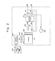
- the pitch error correction circuits 17X, 17Y, 17Z have identical circuit configurations, one of the circuits being shown in Fig. 2.
- the pitch error correction circuit (17X in Fig. 1) shown in Fig. 2 includes a memory 101 for storing corrective values.
- the memory 101 is adapted to store, in the form of a three-dimensional matrix, so-called "absolute" corrective values which correspond to respective sub-regions of space obtained by dividing three-dimensional space into a multiplicity of smaller regions, i.e., "sub-regions".
- An address converter 102 converts the current position (a point defined by X a , Y, Z a ) of the movable body into an address of the location in the memory 101 which stores the corrective value corresponding to the sub-region to which said current position belongs.
- An address register 103 stores the address obtained from the address converter 102.
- a decoder 104 is disposed between the memory 101 and the address register 103.
- the memory 101 is connected to a read control circuit 105 which is in turn connected to a presettable register 106 in which a corrective value CN read out of the memory 101 is preset.
- Numeral 107 denotes an oscillator for generating pulses PL whose function will be described below.
- a reversible counter 112 has its content up-counted by +1 each time a positive corrective pulse +CPX is generated, for a correction in the positive direction and down-counted each time a negative corrective pulse -CPX is generated for a correction in the negative direction. This will be described in further detail below.
- AND gates are designated at numerals 114, 115. When CN>RC holds, AND gate 114 delivers, as the positive corrective pulses +CPX, pulses PL which are generated by the oscillator 107.
- a pitch error correction in accordance with the examples of the present/invention proceeds as follows.
- the interpolator 12 upon receiving a'movement command specified by the paper tape 11, performs a pulse distribution operation and feeds distributed pulses X , Y , Z to the servo circuits 14X, 14Y, 14Z through the pulse mixing circuits 13X, 13Y, 13Z, the servo circuits responding by driving the servo motors 15X, 15Y, 15Z rotatively.
- the servo motors rotate table drive lead screws which in turn transport the machine tool table along the X, Y and Z axes.
- the distributed pulses X p , Yp, Z p in concurrence with the foregoing operation, enter the respective current position counters 16X, 16Y, 16Z which store the thus commanded current position of the table in terms of the values X a , Y , Z along each of the control axes. This is accomplished by up-counting or down- counting the distributed pulses in accordance with their sign.
- the values X a , Y a , Z a specifying the commanded current position of the table enter each one of the pitch error correction circuits 17X through 17Z.
- the address converter 102 in each pitch error correction circuit converts the current table position into an address A i which conforms to the sub-region of space to which the current table position belongs, the address A i then being set in the address register 103.
- the address register 103 addresses the memory 101 by specifying the address Ai.
- the read control circuit 105 reads the corrective value at said address from the memory 101 and sets it in the register 106.
- the comparator 113 constantly compares the content CN of register 106 with the content RC of the reversible counter 112.
- the inputs CN, RC to the comparator 113 become unequal when the corrective value from memory 101 is set in the register 106. If we assume that the corrective value set in register 106 establishes the inequality CN>RC,the coincidence circuit 113 delivers logical "1" on line A+, thereby opening AND gate 114. As a result, pulses PL generated by the oscillator 107 pass through the open AND gate 114 and are delivered as the corrective pulses +CPX for a forward correction.
- the corrective pulses +CPX for the correction in the positive direction were delivered in the foregoing because of the assumption CN >RC.
- the coincidence circuit 113 will open AND gate 115 to deliver the corrective pulses -CPX for negative correction along the X axis.
- the numerical value "7" is set in register 106, and the comparator circuit 113 opens AND gate 115 since CN ("7") is now smaller than RC ("10"), i.e., CN ⁇ RC.
- the AND gate 115 therefore delivers three corrective pulses -CPX to correct the pitch error in the negative direction.
- the value of the count in counter 112 is the arithmetic difference between the number of forward corrective- pulses and the number of backward corrective pulses, and that this represents the actual correction factor. This enables pitch error to be corrected in an accurate manner.
- the mixing circuit 13X in Fig. 1 adds pulses, equivalent in number to the pulses +CPX, to the distributed pulses Xp produced by the interpolator 12, thereby increasing the total number of pulses applied to the servo circuit 14X.
- the mixing circuit 13X subtracts pulses, equivalent in number to the corrective pulses -CPX, from the distributed pulses Xp, thereby decreasing the total number of pulses applied to the servo circuit 14X.
- a corrective operation of this type is performed by pitch error correction circuit 17Y and pulse mixing circuit 13Y, and by pitch error correction circuit 17Z and pulse mixing circuit 13Z, thereby to correct the position of the table along all three control axes. This positional correction is executed each time the table moves from one sub-region of space to another.
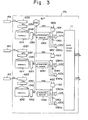
- Fig. 3 is a block diagram useful in describing pitch error correction circuits 17X, 17Y, 17Z for a case where the pitch error correction factors E x , Ey, E may be expressed as follows:
- the pitch error correction circuits 17X, 17Y, 17Z are identical in construction. Segments along the control axes may differ from one another, as may-the corrective values assigned to respective segments and stored in memory, as will be described below. It will therefore be necessary to describe only one of the correction circuits, specifically the correction circuit 17X.
- pitch error correction circuit 17X includes memories 101X, 101Y, 101Z for storing the signed corrective values f x (x), g x (y), h x (z), respectively.
- the range of table movement along each of the X, Y and Z control axes is divided into a plurality of segments, and a corrective value is assigned to each segment.
- Corrective values, as well as their signs, corresponding to the segments along the X-axis are stored in memory 101X.
- corrective values, as well as their signs, corresponding to the segments along the Y-axis are stored in memory 101Y
- corrective values, as well as their signs, corresponding to the segments along the Z-axis are stored in memory 101Z.
- Each corrective value is a so-called incremental corrective value. Accordingly, when the table moves to a position located on a certain segment, pulses are generated, as will be described below, for a correction in the positive or negative direction by an amount corresponding to the corrective value for said segment.
- the sign of the corrective value indicates the direction of the correction for a case where the table is moving in the positive direction. When the table is moving in the negative direction, therefore, the direction of the correction will be the reverse of the sign.
- Address converters 102X, 102Y, 102Z are provided for the respective memories 101X, 101Y, 101Z.
- the address converter 101X converts the current table position X a along the X-axis into an address A x corresponding to the segment to which X a belongs.
- the address converters 101Y, 101Z convert the current positions Y a , Z a along the Y and Z axes into addresses A y , A corresponding to the segments to which Y and Z a belong, respectively.
- the addresses A x , A y , A are set in address registers 103X, 103Y, 103Z, respectively.
- Numerals 104X, 104Y, 104Z denote decoders
- numerals 105X, 105Y, 105Z denote read control circuits.
- Corrective values DX, DY, DZ which have been read out of the respective memories 101X, 101Y, 101Z by the read control circuits, are preset in respective presettable reversible counters 106X, 106Y, 106Z, the content of each reversible counter being down-counted by one count each time an oscillator 107 generates a pulse.
- the reversible counters 106X, 106Y, 106Z have respective output lines l x , l y , l z .
- a reversible counter delivers a "0" on its output line when its content is zero, and a "1" when its content is non-zero.
- NOT gates are designated at 108X, 108Y, 108Z, and AND gates at 109Xp, 109Xm, 109Yp, 109Ym, 109Zp, 109Zm.
- Numerals 110X, 110Y, 110Z denote exclusive-OR gates whose respective inputs are the signs SNX, SNY, SNZ of the corrective values DX, DY, DZ, as well as directional signals MDX, MDY, MDZ.
- the signs SNX, SNY, SNZ are read out of the respective memories 101X, 101Y, 101Z along with the corrective values DX, DY, DZ.
- the directional signals MDX, MDY, MDZ indicate the direction of table movement.
- MDX is a "1" for table movement in the +X direction and a “0” for table movement in the -X direction
- MDY is a "1” for table movement in the + Y direction and a “0” for table movement in the -Y direction
- MDZ is a "1” for movement in the +Z- direction and a "0” for movement in the -Z direction.
- the signs SNX, SNY, SNZ are logical “1” when positive, and logical "0" when negative.
- Numeral 111 denotes a combining circuit which combines the positive corrective pulses +C PX ' from the AND gates 109Xp, 109Yp, 109Zp and the negative corrective pulses -CPX' from the AND gates 109Xm, 109Ym, 109Zm, thereby to produce corrective pulses +C P X for a positive correction and corrective pulses -CPX for a negative correction.
- the current position counters 16X, 16Y, 16Z store the current position of the table in terms of the values X a , Y a , Z along the respective control axes X, Y, Z.
- the address converters 102X, 102Y, 102Z receive the values X , Y , Z and convert them into addresses A y , A , A which correspond to the respective segments on which the above values lie.
- the interpolator 12 in Fig. 1 When the interpolator 12 in Fig. 1 generates the distributed pulses X p for moving the table in the +X direction, the distributed pulses are coupled to the servo circuit 14X through the pulse mixing circuit 13X to drive the servo motor 15X, whereby the table is transported in the +X direction.
- the distributed pulses X p enter the counter 16X and increment its content.
- the address converter 102X When the current position X a along the X-axis moves from one segment to the next adjacent segment, the address converter 102X generates the address A x corresponding to the latter segment and sets this address in the address register 103X, which now addresses the memory 101X accordingly.
- the read control circuit 105X reads, from the address A x of the memory 101X, the pitch error corrective value DX as well as its sign SNX, the corrective value DX being that which has been assigned to the segment just occupied by the commanded current position of the table.
- the read control circuit 105X presets the corrective value DX in the reversible counter 106X and applies the sign SNX (assumed here to be logical "1") to the exclusive-OR gate 110X. Since the content of counter 106X is now non-zero, a "1" appears on its output line l x . Further, since the sign SNX is a "1" (positive) and the directional signal MDX is a "1" (indicating movement in the positive direction), the exlusive-OR gate 110X delivers a "0" which causes the AND gate 109Xp to open.
- the open gate 109Xp permits the pulses PL generated by the oscillator 107 to enter the pulse mixing circuit 111 as the corrective pulses + CPX '.
- the content of reversible counter 106X is decremented by one count each time a pulse PL is generated.
- the delivery of the corrective pulses + CPX ' ends when the content of counter 106X is counted down to zero.
- the sign SNX of the corrective value DX is positive (logical "1") and pulses are being distributed in the -X direction, so that the directional signal MDX is logical "0", the output of the exclusive-OR gate 110X is logical "1". Therefore AND gate 109Xm is opened instead of AND gate 109Xp and delivers the corrective pulses -CPX', produced in the same manner as the corrective pulses +CPX' as described above.
- the AND gates 109Yp, 109Ym, 109Zp, 109Zm also deliver the corrective pulses +CP X ', -CPX' which enter the pulse mixing circuit 111 and are mixed with the distributed pulses, thereby to provide the corrective pulses +C PX , -CPX.
- the pitch error correction circuits 17Y and 1.7Z operate in the same manner as the pitch error correction circuit 17X to produce the corrective signals +CPY, -CPY, +CPZ, -CPZ.
- the present invention enable pitch error to be corrected in accurate fashion to permit highly precise numerical control of a machine tool even when the pitch error along a certain control axis is dependent not only upon the also current position along said control axis but/upon the current position along the other control axes.
- the corrective pulses are generated on the basis of the current position of the movable body, such as a table, following a command to move the body.
- the corrective pulses are generated on the basis of the actual position of the movable body as obtained by supplying the current position counters with signals that indicate where the movable body is actually located at any given time, irrespective of commands.
- a positional error correction system applicable to numerical control wherein a machine tool is controlled along more than one control axis, such as along X and Y control axes. It the machine tool is to be positionally controlled along the X-axis, the position of the machine tool along the X-axis is corrected by a correction factor decided on the basis of the position of the machine tool along that axis and the position of the machine tool along the Y-axis, whereby a positional correction is effected in a highly accurate manner.
- the control axes of the machine tool may include a Z-axis and thus are not restricted to merely the X and Y axes. In such case may be the positional correction / performed using a correction factor decided on the basis of the machine tool position along all three axes.
Applications Claiming Priority (2)
| Application Number | Priority Date | Filing Date | Title |
|---|---|---|---|
| JP55136610A JPS5761906A (en) | 1980-09-30 | 1980-09-30 | Compensating system of position error |
| JP136610/80 | 1980-09-30 |
Publications (3)
| Publication Number | Publication Date |
|---|---|
| EP0049153A2 true EP0049153A2 (fr) | 1982-04-07 |
| EP0049153A3 EP0049153A3 (en) | 1983-08-10 |
| EP0049153B1 EP0049153B1 (fr) | 1989-03-08 |
Family
ID=15179316
Family Applications (1)
| Application Number | Title | Priority Date | Filing Date |
|---|---|---|---|
| EP81304485A Expired EP0049153B1 (fr) | 1980-09-30 | 1981-09-29 | Appareil pour corriger des erreurs de position. |
Country Status (4)
| Country | Link |
|---|---|
| EP (1) | EP0049153B1 (fr) |
| JP (1) | JPS5761906A (fr) |
| KR (1) | KR880000272B1 (fr) |
| DE (1) | DE3177001D1 (fr) |
Cited By (6)
| Publication number | Priority date | Publication date | Assignee | Title |
|---|---|---|---|---|
| EP0334541A1 (fr) * | 1988-03-19 | 1989-09-27 | Electronic Accuracy Systems Limited | Systèmes de compensation d'erreur de machine-outil et similaires |
| US4885449A (en) * | 1986-10-24 | 1989-12-05 | Mitsubishi Denki Kabushiki Kaisha | Electric discharge machine |
| DE4025449A1 (de) * | 1989-08-10 | 1991-02-14 | Mitsubishi Electric Corp | Vorrichtung zur korrektur mechanischer fehler in einer nc-maschine |
| EP0625739A1 (fr) * | 1993-05-18 | 1994-11-23 | Koninklijke Philips Electronics N.V. | Appareil pour déplacer un objet |
| US5492440A (en) * | 1993-05-18 | 1996-02-20 | U.S. Philips Corporation | Apparatus for movement of an object |
| US6286055B1 (en) * | 1996-11-07 | 2001-09-04 | Okuma Corporation | Error correction apparatus for NC machine tool |
Families Citing this family (9)
| Publication number | Priority date | Publication date | Assignee | Title |
|---|---|---|---|---|
| JPS59106006A (ja) * | 1982-12-10 | 1984-06-19 | Toyota Central Res & Dev Lab Inc | インクリメント型駆動量検出装置 |
| JPS60172818U (ja) * | 1984-04-26 | 1985-11-15 | 積水樹脂株式会社 | 防音壁 |
| JPS61292009A (ja) * | 1985-06-19 | 1986-12-22 | Iseki & Co Ltd | 農業用機械における位置検出器の取付位置確認装置 |
| JPS6283609A (ja) * | 1985-10-09 | 1987-04-17 | Yaskawa Electric Mfg Co Ltd | 軌跡アナライザ |
| JPS62185110A (ja) * | 1986-02-12 | 1987-08-13 | Sekisui Jushi Co Ltd | 位置決め用測長装置 |
| JPS62185109A (ja) * | 1986-02-12 | 1987-08-13 | Sekisui Jushi Co Ltd | 位置決め用測長装置 |
| US5444640A (en) * | 1993-01-13 | 1995-08-22 | Mitsubishi Denki Kabushiki Kaisha | Numerical control method for controlling various kinds of machine tools by correcting for thermal displacement |
| EP3339901B1 (fr) * | 2016-12-21 | 2019-04-24 | Hexagon Technology Center GmbH | Module télémétrique laser comprenant une compensation d'erreur adc par variation des moments d'échantillonnage |
| KR102356856B1 (ko) | 2017-08-22 | 2022-01-28 | 두산공작기계 주식회사 | 공작기계의 백래쉬 보정장치 및 보정방법 |
Citations (2)
| Publication number | Priority date | Publication date | Assignee | Title |
|---|---|---|---|---|
| GB1142774A (en) * | 1967-04-17 | 1969-02-12 | Gerber Scientific Instr Co | Error correcting system for use with plotters, machine tools and the like |
| FR1574525A (fr) * | 1967-09-05 | 1969-07-11 |
-
1980
- 1980-09-30 JP JP55136610A patent/JPS5761906A/ja active Pending
-
1981
- 1981-09-29 DE DE8181304485T patent/DE3177001D1/de not_active Expired
- 1981-09-29 KR KR1019810003650A patent/KR880000272B1/ko active
- 1981-09-29 EP EP81304485A patent/EP0049153B1/fr not_active Expired
Patent Citations (2)
| Publication number | Priority date | Publication date | Assignee | Title |
|---|---|---|---|---|
| GB1142774A (en) * | 1967-04-17 | 1969-02-12 | Gerber Scientific Instr Co | Error correcting system for use with plotters, machine tools and the like |
| FR1574525A (fr) * | 1967-09-05 | 1969-07-11 |
Cited By (6)
| Publication number | Priority date | Publication date | Assignee | Title |
|---|---|---|---|---|
| US4885449A (en) * | 1986-10-24 | 1989-12-05 | Mitsubishi Denki Kabushiki Kaisha | Electric discharge machine |
| EP0334541A1 (fr) * | 1988-03-19 | 1989-09-27 | Electronic Accuracy Systems Limited | Systèmes de compensation d'erreur de machine-outil et similaires |
| DE4025449A1 (de) * | 1989-08-10 | 1991-02-14 | Mitsubishi Electric Corp | Vorrichtung zur korrektur mechanischer fehler in einer nc-maschine |
| EP0625739A1 (fr) * | 1993-05-18 | 1994-11-23 | Koninklijke Philips Electronics N.V. | Appareil pour déplacer un objet |
| US5492440A (en) * | 1993-05-18 | 1996-02-20 | U.S. Philips Corporation | Apparatus for movement of an object |
| US6286055B1 (en) * | 1996-11-07 | 2001-09-04 | Okuma Corporation | Error correction apparatus for NC machine tool |
Also Published As
| Publication number | Publication date |
|---|---|
| DE3177001D1 (en) | 1989-04-13 |
| EP0049153B1 (fr) | 1989-03-08 |
| EP0049153A3 (en) | 1983-08-10 |
| KR830008220A (ko) | 1983-11-16 |
| KR880000272B1 (ko) | 1988-03-15 |
| JPS5761906A (en) | 1982-04-14 |
Similar Documents
| Publication | Publication Date | Title |
|---|---|---|
| EP0049153A2 (fr) | Appareil pour corriger des erreurs de position. | |
| US4514813A (en) | System for correcting positional error in numerical control devices | |
| KR920005255B1 (ko) | 고도의 동적처리용 수치제어장치 | |
| US6775586B2 (en) | Numerical controller | |
| US4166543A (en) | Method and means for controlling an industrial robot | |
| EP0465511B1 (fr) | Correction dynamique d'erreurs dues au servomecanisme dans un systeme a commande numerique par ordinateur et son utilisation dans un cycle fixe | |
| US4513379A (en) | Customization window for a computer numerical control system | |
| US4550378A (en) | Method of numerical control and device therefor | |
| EP0081590A1 (fr) | Procede de correction du diametre d'un outil pour un dispositif de commande numerique | |
| EP0075030A1 (fr) | Procede d'usinage a commande numerique | |
| EP2293163B1 (fr) | Contrôleur pour machine-outil et machine-outil à cinq axes ainsi contrôlée | |
| EP0080375B1 (fr) | Méthode et dispositif de mesure de la position réelle dans un système de commande de position | |
| US5563484A (en) | Three-dimensional cutter compensation system | |
| US5075865A (en) | Method and apparatus for involute interpolation | |
| US5218281A (en) | Acceleration/deceleration control method for a numerical control device | |
| EP0364593B1 (fr) | Machine-outil pourvue de deux broches principales | |
| US5181178A (en) | Spindle control command method | |
| US3794902A (en) | Backlash compensating apparatus for numerically controlled machine tool | |
| US5578913A (en) | NC device controlling machining processes with pre- and post-execution in-position values | |
| US4987359A (en) | Numerical control device | |
| US4521721A (en) | Numerical control method | |
| JPH07152417A (ja) | 数値制御装置の工具径路および送り速度制御方式 | |
| US5065333A (en) | Method of involute interpolation in three dimensions | |
| US5475602A (en) | Acceleration constant switching apparatus | |
| US5155424A (en) | Numerical control method |
Legal Events
| Date | Code | Title | Description |
|---|---|---|---|
| PUAI | Public reference made under article 153(3) epc to a published international application that has entered the european phase |
Free format text: ORIGINAL CODE: 0009012 |
|
| AK | Designated contracting states |
Designated state(s): AT BE CH DE FR GB IT LI NL SE |
|
| RAP1 | Party data changed (applicant data changed or rights of an application transferred) |
Owner name: FANUC LIMITED |
|
| PUAL | Search report despatched |
Free format text: ORIGINAL CODE: 0009013 |
|
| AK | Designated contracting states |
Designated state(s): AT BE CH DE FR GB IT LI NL SE |
|
| 17P | Request for examination filed |
Effective date: 19840123 |
|
| RAP1 | Party data changed (applicant data changed or rights of an application transferred) |
Owner name: FANUC LTD |
|
| GRAA | (expected) grant |
Free format text: ORIGINAL CODE: 0009210 |
|
| AK | Designated contracting states |
Kind code of ref document: B1 Designated state(s): DE FR GB |
|
| REF | Corresponds to: |
Ref document number: 3177001 Country of ref document: DE Date of ref document: 19890413 |
|
| ET | Fr: translation filed | ||
| PLBE | No opposition filed within time limit |
Free format text: ORIGINAL CODE: 0009261 |
|
| STAA | Information on the status of an ep patent application or granted ep patent |
Free format text: STATUS: NO OPPOSITION FILED WITHIN TIME LIMIT |
|
| 26N | No opposition filed | ||
| PGFP | Annual fee paid to national office [announced via postgrant information from national office to epo] |
Ref country code: GB Payment date: 19910806 Year of fee payment: 11 |
|
| PGFP | Annual fee paid to national office [announced via postgrant information from national office to epo] |
Ref country code: FR Payment date: 19910909 Year of fee payment: 11 |
|
| PG25 | Lapsed in a contracting state [announced via postgrant information from national office to epo] |
Ref country code: GB Effective date: 19920929 |
|
| GBPC | Gb: european patent ceased through non-payment of renewal fee |
Effective date: 19920929 |
|
| PG25 | Lapsed in a contracting state [announced via postgrant information from national office to epo] |
Ref country code: FR Effective date: 19930528 |
|
| REG | Reference to a national code |
Ref country code: FR Ref legal event code: ST |
|
| PGFP | Annual fee paid to national office [announced via postgrant information from national office to epo] |
Ref country code: DE Payment date: 20000925 Year of fee payment: 20 |