EP0048095B1 - Pumpe für schwere Gase - Google Patents
Pumpe für schwere Gase Download PDFInfo
- Publication number
- EP0048095B1 EP0048095B1 EP19810303882 EP81303882A EP0048095B1 EP 0048095 B1 EP0048095 B1 EP 0048095B1 EP 19810303882 EP19810303882 EP 19810303882 EP 81303882 A EP81303882 A EP 81303882A EP 0048095 B1 EP0048095 B1 EP 0048095B1
- Authority
- EP
- European Patent Office
- Prior art keywords
- pump
- gas
- inlet
- outlet
- manifold
- Prior art date
- Legal status (The legal status is an assumption and is not a legal conclusion. Google has not performed a legal analysis and makes no representation as to the accuracy of the status listed.)
- Expired
Links
- 239000007789 gas Substances 0.000 title claims description 39
- 230000010349 pulsation Effects 0.000 claims description 14
- 238000005086 pumping Methods 0.000 claims description 11
- 230000006835 compression Effects 0.000 claims description 9
- 238000007906 compression Methods 0.000 claims description 9
- 238000010408 sweeping Methods 0.000 claims description 2
- 239000012530 fluid Substances 0.000 description 8
- SANRKQGLYCLAFE-UHFFFAOYSA-H uranium hexafluoride Chemical compound F[U](F)(F)(F)(F)F SANRKQGLYCLAFE-UHFFFAOYSA-H 0.000 description 8
- 238000013021 overheating Methods 0.000 description 3
- 238000013459 approach Methods 0.000 description 1
- 238000010276 construction Methods 0.000 description 1
- 238000013016 damping Methods 0.000 description 1
- 230000003247 decreasing effect Effects 0.000 description 1
- 230000001419 dependent effect Effects 0.000 description 1
- 230000002708 enhancing effect Effects 0.000 description 1
- 230000003993 interaction Effects 0.000 description 1
- 230000003534 oscillatory effect Effects 0.000 description 1
- 238000007493 shaping process Methods 0.000 description 1
- 230000007704 transition Effects 0.000 description 1
Images

Classifications
-
- F—MECHANICAL ENGINEERING; LIGHTING; HEATING; WEAPONS; BLASTING
- F04—POSITIVE - DISPLACEMENT MACHINES FOR LIQUIDS; PUMPS FOR LIQUIDS OR ELASTIC FLUIDS
- F04C—ROTARY-PISTON, OR OSCILLATING-PISTON, POSITIVE-DISPLACEMENT MACHINES FOR LIQUIDS; ROTARY-PISTON, OR OSCILLATING-PISTON, POSITIVE-DISPLACEMENT PUMPS
- F04C29/00—Component parts, details or accessories of pumps or pumping installations, not provided for in groups F04C18/00 - F04C28/00
- F04C29/12—Arrangements for admission or discharge of the working fluid, e.g. constructional features of the inlet or outlet
-
- F—MECHANICAL ENGINEERING; LIGHTING; HEATING; WEAPONS; BLASTING
- F04—POSITIVE - DISPLACEMENT MACHINES FOR LIQUIDS; PUMPS FOR LIQUIDS OR ELASTIC FLUIDS
- F04C—ROTARY-PISTON, OR OSCILLATING-PISTON, POSITIVE-DISPLACEMENT MACHINES FOR LIQUIDS; ROTARY-PISTON, OR OSCILLATING-PISTON, POSITIVE-DISPLACEMENT PUMPS
- F04C18/00—Rotary-piston pumps specially adapted for elastic fluids
- F04C18/08—Rotary-piston pumps specially adapted for elastic fluids of intermeshing-engagement type, i.e. with engagement of co-operating members similar to that of toothed gearing
- F04C18/082—Details specially related to intermeshing engagement type pumps
- F04C18/086—Carter
Definitions
- This invention relates to pumps for pumping heavy gases.
- FR-A-636 382 One type of known pump is shown in FR-A-636 382, in which there is shown a bell shaped inlet passage which is disposed with its widest cross section inside a pump.
- An object of the present invention is to tend to provide a pump which is able to pump heavy gases more efficiently than hitherto.
- a pump for pumping heavy gases comprises two co-operating rotors, the rotors each have an arm for sweeping gas from the pump inlet to its outlet, the arms causing a compression of the gas during part of their movement, an inlet/outlet manifold being provided on the pump, which inlet/outlet manifold includes passages for inlet of gas and for outlet of gas the inlet passage being bell shaped and being disposed with its widest cross section inside the pump and is characterised in that the outlet passage varies from a part annular cross section within the pump to a circular cross section where the manifold is connected to an output conduit, the passages thereby being constructed to provide a minimal velocity change of gas travelling through them, whereby pressure losses of gas within them is minimal, said minimal velocity change being achieved by minimising mechanical obstruction from within the passages, the minimal pressure loss reducing pulsations within the gas owing to said compression and hence allowing efficient pumping of the gas.
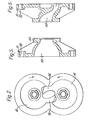
- FIG. 1 An inlet for the pump is generally indicated by 1 and an outlet by 2.
- the inlet 1 and outlet 2 form part of a manifold 3, which manifold 3 is bolted to a housing of the pump 4 by means of studs 5 and 6, which themselves are secured by nuts 7.
- the description is to be read as though a manifold 30 (to be described below) were substituted for manifold 3, which is only illustrated to show manifold positioning.
- a motor for the pump is generally indicated by 8 and this motor drives the pump via a shaft 9.
- the shaft 9 carries the pinion 10, which pinion engages a second pinion 11.
- the pinion 11 is carried upon a shaft 12.
- the shafts 9 and 12 carry two rotors (13, 14) in the form of gear pump members, respectively, within the manifold 3.
- the configuration of the members 13 and 14 can be seen more clearly in Figure 2 to which reference is now also directed, members 13, 14 having an arm 95, 96 respectively.
- the pump gears 10 and 11 and the motor 8 are sealed from gas entering and leaving the pump by means of an endplate 17 which carries seals 18 for the shafts 9 and 12.
- the shafts 9 and 12 are mounted in tapered roller bearings 19 and 20, respectively.
- the motor 8 has a housing 21 which is secured to a plate 22 bolted to the casing 4 by bolts 23. Bearings 24 and 25 are provided on the shafts 9 and 12 respectively, on that part of the casing 4 to which the plate 22 is secured. Therefore, it can be seen that it is not possible for gas to escape from the manifold 3 and the region where the pump members 13 and 14 are located into the remainder of the pump.
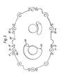
- FIGs 3, 4, 5 and 6 in which a manifold 30 in accordance with the invention is fitted to the pump in place of the manifold 3 (of Figures 1 and 2).
- the manifold 30 is secured to the remainder of the pump by means of boss portions 31 containing passages 32 for bolts or studs.
- the inlet passage into the manifold is in the form of a segment of a circle for the area of cross section of fluid flow. Two recesses 34 and 35 are provided on the segment.
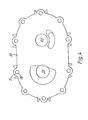
- Figure 4 there is shown a modified manifold without the recesses.
- the inlet passage 33 is bell-shaped as may be seen from Figure 5, the innermost part of the inlet being the part of widest diameter.
- the bell shape provides a buffer volume of gas for damping pulsations.
- an attachment flange 36 is provided for attachment of the inlet manifold to for example pipes (not shown).
- the recesses 34 and 35 which can be seen on the end sauN of the inlet manifold in Figure 3, correspond..,to a slight convolution of the flow passrge as it goes through the manifold.
- the manifold 30 has an outlet passage which can be rnost clearly seen reference to Figure 6.
- the outhet passage indicated by 40 is widest at its 'outermost end and narrowest at its innermost end in Figure 6.
- the cross-section of the flow is circular at its outermost end and in the form of a part annular (the part being ninety degrees) passage at its innermost end. The passage widens to one hundred and ten degrees as it approaches the circular part.
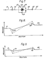
- FIG. 7 shows a diagrammatic model of operational parameters of the pump.
- the pump is indicated by 60.
- Input pressure to the pump is indicated by P1 and outlet pressure by P2.
- P3 which is that pressure which occurs after an inlet port impedance indicated by 11.
- P4 which pressure is a pressure above the outlet pressure P2 of an amount equal to the pressure lost through an outlet port impedance indicated by 12.
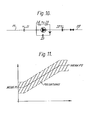
- FIG. 8 in which pump pressure is plotted as ordinate and location along a pump as abscissa.
- the graph of Figure 8 shows, as a full curve, the pressure of air and, as a dotted curve, the pressures of uranium hexafluoride.
- P1 and P2 are the same for the pump in both cases.
- the graph it can be seen that there is a greater drop between P1 and P3 in the case of uranium hexafluoride than air, and similarly in the case of pressure P4 and P2. Therefore, the pump has to do more work with uranium hexafluoride than with air. Consequently, a problem may arise with overheating of the pump.
- Figure 9 shows a pump in a situation where P1 equals P2, that is to say when there is no throughput of fluid through the pump. This is a point that occurs in operation, at that point where the pump members referred to above in connection with Figure 1 as 13 and 14 are at their compression point in their cycle which will be explained in more detail below.
- the pump member 13 rotates in a clockwise manner and the pump member 14 in an anti-clockwise manner. Fluid is drawn in through the inlet and exhausted through the exhaust.
- the members 13 and 14 have arms 95 and 96, which come together during part of the stroke of the pump. This position is shown in Figure 2 and corresponds td a compression position of the pump. Therefore, fluid is drawn in and pushed around by the member 13, slightly compressed in the interaction between the members 13 and 14 and then pushed out of the exhaust manifold by the member 14.
- the inlet port and outlet port have impedances 11 and 12 which become of significance when uranium hexafluoride is being pumped when compared with the pumping of air. Therefore, it is important that these impedances be reduced, so that too much power is not used by the pump tending to cause overheating thereof. Therefore, the inlet of the manifold 30 is constructed so as to have reduced mechanical obstruction therein, i.e. substantially no mechanical obstruction to ingress of the heavy gas so that a minimal gas velocity is achieved. Also, the inlet widens out in the bell shape described above with reference to Figure 5. However, such- an enlarged inlet port may give rise to rotor slippage.
- uranium hexafluoride would be an improved fluid for the purpose of pumping the input compared with air. This is because the volumetric slippage between the rotors for a given pump outlet and inlet pressure is less for a dense gas than a light gas thereby enhancing the pump throughput, the relative density of uranium hexafluoride to air being 12:2.
Landscapes
- Engineering & Computer Science (AREA)
- Mechanical Engineering (AREA)
- General Engineering & Computer Science (AREA)
- Structures Of Non-Positive Displacement Pumps (AREA)
- Applications Or Details Of Rotary Compressors (AREA)
Claims (1)
Applications Claiming Priority (2)
| Application Number | Priority Date | Filing Date | Title |
|---|---|---|---|
| GB8028827 | 1980-09-05 | ||
| GB8028827 | 1980-09-05 |
Publications (2)
| Publication Number | Publication Date |
|---|---|
| EP0048095A1 EP0048095A1 (de) | 1982-03-24 |
| EP0048095B1 true EP0048095B1 (de) | 1983-12-14 |
Family
ID=10515897
Family Applications (1)
| Application Number | Title | Priority Date | Filing Date |
|---|---|---|---|
| EP19810303882 Expired EP0048095B1 (de) | 1980-09-05 | 1981-08-25 | Pumpe für schwere Gase |
Country Status (2)
| Country | Link |
|---|---|
| EP (1) | EP0048095B1 (de) |
| DE (1) | DE3161646D1 (de) |
Families Citing this family (5)
| Publication number | Priority date | Publication date | Assignee | Title |
|---|---|---|---|---|
| GB9316539D0 (en) * | 1993-08-10 | 1993-09-29 | Drum Int Ltd | Rotary compressor |
| DE29905249U1 (de) * | 1999-03-22 | 1999-12-30 | Werner Rietschle GmbH + Co. KG, 79650 Schopfheim | Pumpe zur Erzeugung von Druck und Unterdruck |
| US6729863B2 (en) | 1999-03-22 | 2004-05-04 | Werner Rietschle Gmbh & Co. Kg | Rotary pump having high and low pressure ports in the housing cover |
| DE20216504U1 (de) * | 2002-10-25 | 2003-03-06 | Werner Rietschle GmbH + Co. KG, 79650 Schopfheim | Verdrängermaschine mit gegensinnig laufenden Rotoren |
| DE102010015151A1 (de) * | 2010-04-16 | 2011-10-20 | Knorr-Bremse Systeme für Schienenfahrzeuge GmbH | Verdichterflansch für Schraubenverdichter |
Family Cites Families (4)
| Publication number | Priority date | Publication date | Assignee | Title |
|---|---|---|---|---|
| FR636382A (de) * | 1928-04-07 | |||
| US2469936A (en) * | 1945-03-14 | 1949-05-10 | Paul C Tabbert | Rotary pump |
| US3513476A (en) * | 1967-06-21 | 1970-05-19 | Tokyo Shibaura Electric Co | Rotary compressors |
| US3844696A (en) * | 1973-08-21 | 1974-10-29 | Gen Motors Corp | Fluid pump noise reduction means |
-
1981
- 1981-08-25 EP EP19810303882 patent/EP0048095B1/de not_active Expired
- 1981-08-25 DE DE8181303882T patent/DE3161646D1/de not_active Expired
Also Published As
| Publication number | Publication date |
|---|---|
| EP0048095A1 (de) | 1982-03-24 |
| DE3161646D1 (en) | 1984-01-19 |
Similar Documents
| Publication | Publication Date | Title |
|---|---|---|
| JPH0315038B2 (de) | ||
| CN105485022B (zh) | 节段式多级离心泵 | |
| EP0048095B1 (de) | Pumpe für schwere Gase | |
| CN110017282B (zh) | 气流脉动衰减装置以及空气压缩机 | |
| CN108506184B (zh) | 一种无脉动大行程柱塞泵 | |
| CN201155463Y (zh) | 新型轴向力平衡装置离心泵 | |
| CN208416966U (zh) | 一种结构精简的减振离心泵 | |
| JPH0134300B2 (de) | ||
| CN111963475B (zh) | 轴向力自平衡的叶片泵机组 | |
| CN107387431A (zh) | 离心机压缩机 | |
| FI62894C (fi) | Vaetskeringpump | |
| CN209244852U (zh) | 一种化工流程泵结构 | |
| CN222102364U (zh) | 一种永磁屏蔽管道叠加泵 | |
| CN1869449B (zh) | 鼓风机 | |
| CN216842272U (zh) | 一种透平真空泵重型密封结构 | |
| CN223398951U (zh) | 一种多级泵出水段及水泵系统 | |
| US4473339A (en) | Liquid pump | |
| CN223707849U (zh) | 一种串联式柱塞泵 | |
| CN223075823U (zh) | 一种叶轮及泵 | |
| CN206054313U (zh) | 双涡壳导流机构型多级离心泵 | |
| CN223297484U (zh) | 一种无机械密封件内置电机转子压缩机 | |
| CN220452318U (zh) | 离心泵 | |
| CN222254363U (zh) | 一种磁阻电机多级对转泵 | |
| CN217632946U (zh) | 一种离心式循环泵 | |
| CN215333458U (zh) | 一种双水室水泵 |
Legal Events
| Date | Code | Title | Description |
|---|---|---|---|
| PUAI | Public reference made under article 153(3) epc to a published international application that has entered the european phase |
Free format text: ORIGINAL CODE: 0009012 |
|
| AK | Designated contracting states |
Designated state(s): CH DE FR GB LI NL |
|
| TCNL | Nl: translation of patent claims filed | ||
| TCNL | Nl: translation of patent claims filed | ||
| 17P | Request for examination filed |
Effective date: 19820504 |
|
| DET | De: translation of patent claims | ||
| GRAA | (expected) grant |
Free format text: ORIGINAL CODE: 0009210 |
|
| STAA | Information on the status of an ep patent application or granted ep patent |
Free format text: STATUS: THE PATENT HAS BEEN GRANTED |
|
| AK | Designated contracting states |
Designated state(s): CH DE FR GB LI NL |
|
| REF | Corresponds to: |
Ref document number: 3161646 Country of ref document: DE Date of ref document: 19840119 |
|
| EL | Fr: translation of claims filed | ||
| ET | Fr: translation filed | ||
| RAP2 | Party data changed (patent owner data changed or rights of a patent transferred) |
Owner name: BRITISH NUCLEAR FUELS PLC |
|
| PLBI | Opposition filed |
Free format text: ORIGINAL CODE: 0009260 |
|
| PLBG | Opposition deemed not to have been filed |
Free format text: ORIGINAL CODE: 0009274 |
|
| 26 | Opposition filed |
Opponent name: LEYBOLD - HERAEUS GMBH Effective date: 19840912 |
|
| 26D | Opposition deemed not to have been filed |
Opponent name: LEYBOLD - HERAEUS GMBH Effective date: 19840915 |
|
| PGFP | Annual fee paid to national office [announced via postgrant information from national office to epo] |
Ref country code: FR Payment date: 19940711 Year of fee payment: 14 |
|
| PGFP | Annual fee paid to national office [announced via postgrant information from national office to epo] |
Ref country code: CH Payment date: 19940714 Year of fee payment: 14 |
|
| PGFP | Annual fee paid to national office [announced via postgrant information from national office to epo] |
Ref country code: GB Payment date: 19940715 Year of fee payment: 14 |
|
| PGFP | Annual fee paid to national office [announced via postgrant information from national office to epo] |
Ref country code: DE Payment date: 19940720 Year of fee payment: 14 |
|
| PGFP | Annual fee paid to national office [announced via postgrant information from national office to epo] |
Ref country code: NL Payment date: 19940831 Year of fee payment: 14 |
|
| PG25 | Lapsed in a contracting state [announced via postgrant information from national office to epo] |
Ref country code: GB Effective date: 19950825 |
|
| PG25 | Lapsed in a contracting state [announced via postgrant information from national office to epo] |
Ref country code: LI Effective date: 19950831 Ref country code: CH Effective date: 19950831 |
|
| PG25 | Lapsed in a contracting state [announced via postgrant information from national office to epo] |
Ref country code: NL Effective date: 19960301 |
|
| REG | Reference to a national code |
Ref country code: CH Ref legal event code: PL |
|
| GBPC | Gb: european patent ceased through non-payment of renewal fee |
Effective date: 19950825 |
|
| PG25 | Lapsed in a contracting state [announced via postgrant information from national office to epo] |
Ref country code: FR Effective date: 19960430 |
|
| NLV4 | Nl: lapsed or anulled due to non-payment of the annual fee |
Effective date: 19960301 |
|
| PG25 | Lapsed in a contracting state [announced via postgrant information from national office to epo] |
Ref country code: DE Effective date: 19960501 |
|
| REG | Reference to a national code |
Ref country code: FR Ref legal event code: ST |
|
| RIN2 | Information on inventor provided after grant (corrected) |
Inventor name: THOMAS, IDWAL MILES |