EP0047942A2 - Agricultural machine, in particular a tractor - Google Patents
Agricultural machine, in particular a tractor Download PDFInfo
- Publication number
- EP0047942A2 EP0047942A2 EP81106982A EP81106982A EP0047942A2 EP 0047942 A2 EP0047942 A2 EP 0047942A2 EP 81106982 A EP81106982 A EP 81106982A EP 81106982 A EP81106982 A EP 81106982A EP 0047942 A2 EP0047942 A2 EP 0047942A2
- Authority
- EP
- European Patent Office
- Prior art keywords
- axle
- agricultural machine
- machine according
- gear
- shaft
- Prior art date
- Legal status (The legal status is an assumption and is not a legal conclusion. Google has not performed a legal analysis and makes no representation as to the accuracy of the status listed.)
- Withdrawn
Links
Images


Classifications
-
- B—PERFORMING OPERATIONS; TRANSPORTING
- B60—VEHICLES IN GENERAL
- B60B—VEHICLE WHEELS; CASTORS; AXLES FOR WHEELS OR CASTORS; INCREASING WHEEL ADHESION
- B60B35/00—Axle units; Parts thereof ; Arrangements for lubrication of axles
- B60B35/001—Axles of the portal type, i.e. axles designed for higher ground clearance
-
- B—PERFORMING OPERATIONS; TRANSPORTING
- B60—VEHICLES IN GENERAL
- B60B—VEHICLE WHEELS; CASTORS; AXLES FOR WHEELS OR CASTORS; INCREASING WHEEL ADHESION
- B60B35/00—Axle units; Parts thereof ; Arrangements for lubrication of axles
- B60B35/003—Steerable axles
-
- B—PERFORMING OPERATIONS; TRANSPORTING
- B60—VEHICLES IN GENERAL
- B60B—VEHICLE WHEELS; CASTORS; AXLES FOR WHEELS OR CASTORS; INCREASING WHEEL ADHESION
- B60B35/00—Axle units; Parts thereof ; Arrangements for lubrication of axles
- B60B35/02—Dead axles, i.e. not transmitting torque
- B60B35/10—Dead axles, i.e. not transmitting torque adjustable for varying track
- B60B35/1009—Dead axles, i.e. not transmitting torque adjustable for varying track operated manually
- B60B35/1027—Dead axles, i.e. not transmitting torque adjustable for varying track operated manually comprising a clamping mechanism
-
- B—PERFORMING OPERATIONS; TRANSPORTING
- B60—VEHICLES IN GENERAL
- B60B—VEHICLE WHEELS; CASTORS; AXLES FOR WHEELS OR CASTORS; INCREASING WHEEL ADHESION
- B60B35/00—Axle units; Parts thereof ; Arrangements for lubrication of axles
- B60B35/02—Dead axles, i.e. not transmitting torque
- B60B35/10—Dead axles, i.e. not transmitting torque adjustable for varying track
- B60B35/1072—Dead axles, i.e. not transmitting torque adjustable for varying track by transversally movable elements
- B60B35/109—Dead axles, i.e. not transmitting torque adjustable for varying track by transversally movable elements the element is an axle part
-
- B—PERFORMING OPERATIONS; TRANSPORTING
- B60—VEHICLES IN GENERAL
- B60B—VEHICLE WHEELS; CASTORS; AXLES FOR WHEELS OR CASTORS; INCREASING WHEEL ADHESION
- B60B35/00—Axle units; Parts thereof ; Arrangements for lubrication of axles
- B60B35/12—Torque-transmitting axles
- B60B35/121—Power-transmission from drive shaft to hub
- B60B35/122—Power-transmission from drive shaft to hub using gearings
- B60B35/124—Power-transmission from drive shaft to hub using gearings of the helical or worm type
-
- B—PERFORMING OPERATIONS; TRANSPORTING
- B60—VEHICLES IN GENERAL
- B60K—ARRANGEMENT OR MOUNTING OF PROPULSION UNITS OR OF TRANSMISSIONS IN VEHICLES; ARRANGEMENT OR MOUNTING OF PLURAL DIVERSE PRIME-MOVERS IN VEHICLES; AUXILIARY DRIVES FOR VEHICLES; INSTRUMENTATION OR DASHBOARDS FOR VEHICLES; ARRANGEMENTS IN CONNECTION WITH COOLING, AIR INTAKE, GAS EXHAUST OR FUEL SUPPLY OF PROPULSION UNITS IN VEHICLES
- B60K17/00—Arrangement or mounting of transmissions in vehicles
- B60K17/22—Arrangement or mounting of transmissions in vehicles characterised by arrangement, location, or type of main drive shafting, e.g. cardan shaft
-
- B—PERFORMING OPERATIONS; TRANSPORTING
- B60—VEHICLES IN GENERAL
- B60B—VEHICLE WHEELS; CASTORS; AXLES FOR WHEELS OR CASTORS; INCREASING WHEEL ADHESION
- B60B2310/00—Manufacturing methods
- B60B2310/30—Manufacturing methods joining
- B60B2310/305—Manufacturing methods joining by screwing
-
- B—PERFORMING OPERATIONS; TRANSPORTING
- B60—VEHICLES IN GENERAL
- B60B—VEHICLE WHEELS; CASTORS; AXLES FOR WHEELS OR CASTORS; INCREASING WHEEL ADHESION
- B60B2310/00—Manufacturing methods
- B60B2310/30—Manufacturing methods joining
- B60B2310/306—Manufacturing methods joining by clamping or wedging, e.g. by clamping inserts as joining means
-
- B—PERFORMING OPERATIONS; TRANSPORTING
- B60—VEHICLES IN GENERAL
- B60Y—INDEXING SCHEME RELATING TO ASPECTS CROSS-CUTTING VEHICLE TECHNOLOGY
- B60Y2200/00—Type of vehicle
- B60Y2200/20—Off-Road Vehicles
- B60Y2200/22—Agricultural vehicles
- B60Y2200/221—Tractors
Definitions
- the invention relates to an agricultural machine, in particular a tractor, with a mechanically driven, track-adjustable front axle, the support axle and side shafts of which are made in several parts and are adjustable in length in the axial direction, with at least the support axle being suspended on the vehicle frame and the differential and angular gear belonging to the front-wheel drive via a shaft guided to the front by the main transmission can be driven and is arranged approximately in the center of the axis.
- Such a front axle is known in the case of an agricultural tractor manufactured by the Belarus (USSR) company.
- USSR agricultural tractor manufactured by the USSR
- This is an oscillating, suspended hollow axle, in which the front gearbox housing is integrated approximately in the middle and within which the side shafts leading to the wheel drive run.
- the essentially round hollow axle which takes over the supporting function, is telescopically adjustable to the left and right of the axle center piece or front gear housing using clamping elements.
- the invention is therefore based on the object to improve the known prior art and to provide a front axle construction which allows a mechanical drive for all selectable track widths using existing components which have been tried and tested in terms of their robustness, to a certain extent according to the modular principle.
- a preferred embodiment of the invention is characterized in that the axle center piece belonging to the front axle is pivotally attached to the trestle and has connections for a left and right semiaxis, and that a housing for the differential and angular gear is provided in the immediate vicinity, but optionally separately is, the left and right drive shafts are articulated on the gear and wheel side and run outside and approximately parallel to the load-bearing axle construction.
- track-adjustable front semiaxes in particular also with a square cross-section (cf. DE-AS 10 90 894) have also been known for decades, such as telescopically adjustable drive shafts, in particular also with universal joint connection (cf. DE-AS 10 70 936, Fig. 1a), but the presence of these components has obviously not suggested the concept according to the invention, rather the hollow axle constructions have recently been designed to be more complex, or a hydraulic drive of the front wheels was preferred in connection with a robust, adjustable front axle.
- the front axle center piece is attached to the support bracket in an oscillating manner.
- Two main variants of the invention consist in the fact that the housing for the differential and angular gear belonging to the front-wheel drive is either fixedly attached to the trestle or, in a structurally more or less extensive association with the axle center piece, is attached to the trestle in an oscillating manner.
- the first-mentioned solution with a fixed gear housing is less expensive to produce
- the second-mentioned solution is the more robust one with regard to the stress on the drive shafts. Since in the second case the support axle and drive shaft oscillate together around the same point, the transition to the wheels to be driven is relatively simple.
- the support axis and drive axis (side shafts) run practically parallel to each other. Furthermore can be cast in one piece in the center axle and gearbox housing and then has left and right cast-on axle connecting pieces for the semi-axles.
- Fig. 1 shows a front view of the front axle, the left half of the figure is only partially shown.
- the front cladding panel which is not described in any more detail, is indicated, underneath the support bracket, indicated at 70, is visible, in the middle, the self-aligning bearing, indicated at 72, on which the axle center piece 120 is pivoted.
- the axis center piece 120 continues on the left and right and has a perforated strip, not specified, to which the left and right semiaxis 122 can be adjustably fastened by means of screw connections 124.
- the perforated strip shown is suitable for five different track gauges. A double-hole strip arranged one above the other can be recommended.
- the axle connecting pieces of the axially produced axle center piece preferably have a rectangular solid profile with a guide groove for the semi-axis 122 to be connected, which has a corresponding guide web. Hollow profiles can also be used in principle. It is advisable to clasp the axle connection piece 120a and semi-axles 122 in order to ensure the connection of the axles when the bolts are removed. The same applies to the profile shape of the left and right semiaxis 122, which opens into a fork to which the front wheels 110 are fastened via kingpin 114.
- the kingpin 114 are advantageously inclined backwards in the plane of the vehicle's longitudinal axis in the sense of an oversized caster with 10 to 30 degrees in order to achieve a larger wheel lock of the front wheel on the inside of the curve, preferably 11 to 15 degrees (see FIG. 8).
- the gear housing 100 is either e.g. firmly attached to the trestle by means of bolts - as shown here and in FIG. 2 - or structurally combined with the trestle, in particular in the sense of a cast construction.
- the gear-dependent shaft running forward from the main transmission is designated, which opens into the center of the transmission housing 100 and from there drives the rotationally displaceable drive shafts 104 via the front transmission (not shown) via a universal joint 80.
- the left and right drive shafts 10 4 are shown in the figures as a telescopic shaft. It generally consists of polygonal profiles that can be pushed one into the other, e.g. are longitudinally displaceable by means of rolling elements.
- the drive shafts 104 drive the wheel planetary gear 112 via a further universal joint 80 and the axle journal 112a.
- a further universal joint 80 and the axle journal 112a instead of the universal joints, homokinetic joints can of course also be used.
- the drive shafts 104 lie somewhat in front of and below the supporting semi-axles 122 and are in the region of the front wheel by the half formed there in the form of a fork axles 122 encompassed. These are shown in the figures in such a way that a view of the drive shafts 104 passing through is possible.
- the axis of the universal joint 80 on the wheel side must coincide with the axis of the kingpin 112. In this case, this axis does not necessarily have to be formed exactly vertically, but in a known manner an inclination of up to 5 degrees inwards and an inclination of this axis upwards of about 12 degrees can be recommended for reasons of a smaller turning circle.
- FIG. 1 also shows the power take-off shaft 60 required for the devices attached to the front, which is mounted here in the gear housing 100 fastened to the support bracket 70.
- the extension of the PTO shaft 60 shown in FIG. 2 is designated there by 62 and runs to the rear above the shaft 102 coming from the main transmission.
- the shaft 62 is normally gear-independent and preferably has an approximately constant speed of e.g. 1000 rpm. on.
- Fig. 2 which shows the embodiment shown in Fig. 1 from below, the steering lever 136 is also visible, which acts on the steering tie rod, not shown.
- the fixed housing 100 can be formed in a substantially bell-shaped manner in one part or, if appropriate, also in two parts with a separate cover.
- Fig. 3 also shows a view from below, wherein compared to the embodiment of FIGS. 1 and 2, a change is made in that the drive shafts 104 are angled rearward by an angle of about 7 to 15 degrees to an increased angle of impact of the respective to reach the inner front wheel.
- the left side of FIG. 3 is not shown in detail in the drawing, it is to be thought of as symmetrical to the central axis.
- FIG. 4 shows a variant of the axis center piece 120 in the view from below. While FIG. 3 shows an axle center piece in a conventional design, which is mounted twice behind the fixed gear housing 100, in FIG. 4 an axle center piece 120 is shown which encompasses the gear housing 100 in a frame-like manner and is pivotally mounted in front of and behind it by means of a self-aligning bearing 72.
- This arrangement requires less space than the conventional one according to FIG. 3.
- FIG.Fig. 4 the left half of the picture, which is to be thought of symmetrically, is not drawn; the circular joints are only indicated schematically.
- FIG. 5 shows a view of the front axle from the front, with the transmission housing and axle center piece 120 being structurally combined and both being attached so as to be able to oscillate by means of the bearing 72.
- Transmission housing and axle center piece 120 can be cast from one piece.
- the upper side of the gear housing 100 oscillates - as shown in particular in FIG. 8 - in a recess in the support bracket 70.
- the recess can be made with a corresponding design of the gear housing 100 naturally also eliminated. To understand the illustration, reference can otherwise be made to what has been said about FIG. 1.
- FIG. 5a shows a view of the parts belonging to the steering of the wheel which is part of FIG. 5 and is better shown for the sake of clarity.
- the steering cylinder 132 can - as indicated - be mounted directly below on the oscillating gear housing.
- the steering cylinder acts on the steering tie rod 13 0 via a joint protected, for example, with bellows, which in turn acts on the ball joint head 134 via the steering lever (not shown).
- the steering tie rod 130 can be adjusted accordingly, for example five times, to suit the axial track adjustability of the front axle, expediently in a telescopic construction as shown.
- the adjustment is most conveniently carried out by means of clamping pieces, for example screws, which engage in a form-fitting manner in the inner running profile in corresponding A b stands.
- Fig. 6 shows a view of the in.Fig. 5 embodiment shown from below with the axle connectors ' 120a cast onto the axle center piece or gearbox housing.
- the semi-axis flanged on by means of two bolt connections is again designated 122.
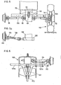
- FIG. 7 shows a partial side view of the embodiment shown in FIG. 1.
- the support bracket 70 is located underneath the side of the front cladding. This is behind the gear housing horizontal axis center piece 120 - as can be seen - is mounted twice on the trestle.
- the PTO shaft 60 for the devices attached to the front passes through the transmission housing and runs to the rear above the shaft 102 for the front transmission.
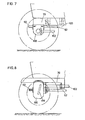
- FIG. 8 shows a partial view of the embodiment shown in FIG. 5, again from the side.
- the support bracket 70 is only hinted at.
- the PTO shaft 60 which continues via a joint in the associated drive shaft 62, is arranged below the shaft 102.
- the preferred inclination of the kingpin 114 in the plane of the vehicle longitudinal axis in the sense of an oversized caster is evident.
- a further inclination from the vertical in the sense of spreading can be recommended.
- FIG. 9 shows a partial view of a portal axis from the front, only the parts that appear to be essential being identified in more detail.
- the right drive shaft 104 opens into the housing 92 via a universal joint 80 and a bevel gear 94, which encloses the approximately perpendicular vertical shaft 90.
- the king shaft in turn drives the bevel gear 116 connected to the journal 112a of the planetary gear 112 via a bevel gear.
- the semiaxis .122 indicated behind the drive shaft 104 is supported on the housing construction 92.
- the ball joint head 134 engages on the rotatably mounted housing 92.
- Such a design of the portal axis enables the large ground clearance preferred for some agricultural tractors.
Abstract
Description
Die Erfindung betrifft eine Landmaschine, insbesondere einen Traktor, mit mechanisch angetriebener spurverstellbarer Vorderachse, deren Tragachse und Seitenwellen mehrteilig und in axialer Richtung längenverstellbar ausgebildet sind, wobei zumindest die Tragachse pendelnd am Fahrzeugrahmen aufgehängt ist und das zum Frontantrieb gehörige Differential- und Winkel- Getriebe über eine vom Hauptgetriebe nach vorne geführte Welle antreibbar und etwa in Achsmitte angeordnet ist.The invention relates to an agricultural machine, in particular a tractor, with a mechanically driven, track-adjustable front axle, the support axle and side shafts of which are made in several parts and are adjustable in length in the axial direction, with at least the support axle being suspended on the vehicle frame and the differential and angular gear belonging to the front-wheel drive via a shaft guided to the front by the main transmission can be driven and is arranged approximately in the center of the axis.
Eine derartige Vorderachse ist im Falle eines von der Firma Belarus (UdSSR) gefertigten Ackerschleppers bekannt. Dabei handelt es sich um eine pendelnd aufgehängte Hohlachse, in die das Frontgetriebe-Gehäuse etwa mittig integriert ist und innerhalb derer die zum Radantrieb führenden Seitenwellen verlaufen. Die im wesentlichen rund ausgebildete Hohlachse, welche die Tragfunktion übernimmt, ist links und rechts vom Achsmittelstück bzw. Frontgetriebe-Gehäuse unter Verwendung von Klemmelementen teleskopartig spurverstellbar.Such a front axle is known in the case of an agricultural tractor manufactured by the Belarus (USSR) company. This is an oscillating, suspended hollow axle, in which the front gearbox housing is integrated approximately in the middle and within which the side shafts leading to the wheel drive run. The essentially round hollow axle, which takes over the supporting function, is telescopically adjustable to the left and right of the axle center piece or front gear housing using clamping elements.
Dieser anspruchsvollen Sonderkonstruktion haftet allerdings Nachteil an,daß sich das Fahrzeug bzw. die Landmaschine erheblich verteuert ohne auf der anderen Seite in bezug auf Robustheit und Lebensdauer voll zu befriedigen. Man muß vielmehr davon ausgehen, daß die Hohlachse die von den frontgetriebenen Rädern herkommende Drehmomente und Aufstellkräfte nicht immer in wünschenswertem Maße verkraftet.However, this demanding special construction has the disadvantage that the vehicle or the agricultural machine is considerably more expensive without, on the other hand, being fully satisfactory in terms of robustness and service life. One must rather assume that the hollow axle does not always cope with the torques and lifting forces coming from the front-wheel drive to the desired extent.
Der Erfindung liegt daher die Aufgabe zugrunde, den bekannten Stand der Technik zu verbessern und eine Vorderachskonstruktion zu schaffen, die einen mechanischen Antrieb für alle wählbaren Spurbreiten gestattet unter Verwendung bereits vorhandener in bezug auf ihre Robustheit erprobter Komponenten, gewissermaßen nach dem Baukastenprinzip.The invention is therefore based on the object to improve the known prior art and to provide a front axle construction which allows a mechanical drive for all selectable track widths using existing components which have been tried and tested in terms of their robustness, to a certain extent according to the modular principle.
Diese Aufgabe wird ausgehend von einer Landmaschine der eingangs genannten Art gemäß der Erfindung dadurch gelöst, daß Trag- und Treibfunktion der Vorderachse von baulich weitgehend voneinander getrennten, separat voneinander zu den Vorderrädern verlaufenden und gesondert bezüglich Spurbreite zu verstellenden Komponenten wahrgenommen werden.This object is achieved on the basis of an agricultural machine of the type mentioned at the outset according to the invention in that the carrying and driving functions of the front axle are performed by components which are largely structurally separate from one another, run separately from one another to the front wheels and can be adjusted separately with respect to the track width.
Diese konstruktive Trennung von Trag- und Triebfunktion ermöglicht die Verwendung einer spurverstellbaren Standard-Vorderachse, wie sie insbesondere in Form von Vierkant-Profilen mit doppelter Lochleiste, bei der die Profilstücke nebeneinander entlang einer gemeinsamen Seitenfläche verschoben und mittels der Lochleiste und entsprechender Bolzen verstellt werden können, auch für extreme Belastungsanforderungen erprobt ist insbesondere hinsichtlich der Radaufstandskräfte bei größeren Spurweiten.This structural separation of the support and drive function enables the use of a track-adjustable standard front axle, as is the case in particular in the form of square profiles with double perforated strips, in which the profile pieces can be moved next to each other along a common side surface and adjusted using the perforated strip and corresponding bolts , has also been tested for extreme load requirements, particularly with regard to wheel contact forces with larger track gauges.
Eine bevorzugte Ausführungsform der Erfindung zeichnet sich dadurch aus, daß das zur Vorderachse gehörige Achsmittelstück pendelnd am Tragbock befestigt ist und Anschlüsse für eine linke und rechte Halbachse aufweist, und daß in unmittelbarer Nachbarschaft, jedoch wahlweise getrennt, ein Gehäuse für das Differential- und Winkelgetriebe vorgesehen ist, dessen linke und rechte Antriebswellen getriebe- und radseitig gelenkig angeschlossen sind und außerhalb sowie etwa parallel zur tragenden Achskonstruktion verlaufen.A preferred embodiment of the invention is characterized in that the axle center piece belonging to the front axle is pivotally attached to the trestle and has connections for a left and right semiaxis, and that a housing for the differential and angular gear is provided in the immediate vicinity, but optionally separately is, the left and right drive shafts are articulated on the gear and wheel side and run outside and approximately parallel to the load-bearing axle construction.
Bei einer spurverstellbaren mechanisch angetriebenen Vorderachse gemäß der Erfindung ergeben sich damit folgende Vorteile:
- - Es wird von überwiegend schon erprobten und vorhandenen Bauelementen ausgegangen;
- - Damit gestaltet sich die Fertigung einfacher und wirtschaftlicher und kommt bezüglich der Produktion verschiedener Typen mit einer weit geringeren Anzahl von Bauelementen aus;
- - Die Spurverstellbarkeit gestaltet sich übersichtlicher und einfacher und vor allem zuverlässiger im Vergleich zur Teleskop-Hohlachse;
- - Die robuste Tragachs-Konstruktion gewährleistet lange Lebensdauer bei höchster Beanspruchbarkeit;
- - Die im Gegensatz zur intergrierten Hohlachse leichte Zugänglichkeit der Antriebskomponenten erleichtert einen etwa notwendigen Austausch einzelner Teile erheblich.
- - It is assumed that most of the components have already been tried and tested;
- - This makes the production easier and more economical and manages with the production of different types with a far smaller number of components;
- - The track adjustability is clearer and easier and, above all, more reliable compared to the telescopic hollow axis;
- - The robust support axle construction ensures a long service life with the highest level of durability;
- - In contrast to the integrated hollow axis, the easy accessibility of the drive components makes it easier any necessary replacement of individual parts significantly.
Zwar sind spurverstellbare vordere Halbachsen, insbesondere auch mit Vierkant-Querschnitt (vgl. DE-AS 10 90 894) ebenso seit Jahrzehnten bekannt wie etwa teleskopartig verstellbare Antriebswellen, insbesondere auch mit Kreuzgelenk-Anschluß (vgl. DE-AS 10 70 936, Fig. 1a), jedoch hat das Vorhandensein dieser Komponenten offensichtlich die erfindungsgemäße Konzeption nicht nahegelegt, vielmehr sind in letzter Zeit die Hohlachskonstruktionen aufwendiger gestaltet worden oder aber es wurde in Verbindung mit einer robusten spurverstellbaren Standard-Vorderachse ein hydraulischer Antrieb der Vorderräder bevorzugt.It is true that track-adjustable front semiaxes, in particular also with a square cross-section (cf. DE-AS 10 90 894) have also been known for decades, such as telescopically adjustable drive shafts, in particular also with universal joint connection (cf. DE-AS 10 70 936, Fig. 1a), but the presence of these components has obviously not suggested the concept according to the invention, rather the hollow axle constructions have recently been designed to be more complex, or a hydraulic drive of the front wheels was preferred in connection with a robust, adjustable front axle.
Bei einer weiter bevorzugten Ausführungsform der Erfindung ist das Vorderachsmittelstück pendelnd am Tragbock befestigt. Zwei Hauptvarianten der Erfindung bestehen darin, daß das Gehäuse für das zum Frontantrieb gehörige Differential- und Winkelgetriebe entweder feststehend am Tragbock befestigt ist oder aber in baulich mehr oder weniger weitgehender Vereinigung mit dem Achsmittelstück mit diesem zusammen pendelnd am Tragbock befestigt ist. Die erstgenannten Lösung mit feststehendem Getriebegehäuse ist kostengünstiger herstellbar, die zweitgenannte Lösung ist bezüglich der Beanspruchung der Antriebswellen die noch robustere. Da im zweitgenannten Falle Tragachse und Antriebswelle gemeinsam um denselben Punkt pendeln, gestaltet sich der Übergang auf die anzutreibenden Räder verhältnismäßig einfach. Tragachse und Treibachse (Seitenwellen) laufen praktisch parallel zueinander. Außerdem läßt sich Achsmittelstück und Getriebegehäuse baulich vereinigt als ein Stück gießen und weist dann links und rechts angegossene Achanschlußstücke für die Halbachsen auf.In a further preferred embodiment of the invention, the front axle center piece is attached to the support bracket in an oscillating manner. Two main variants of the invention consist in the fact that the housing for the differential and angular gear belonging to the front-wheel drive is either fixedly attached to the trestle or, in a structurally more or less extensive association with the axle center piece, is attached to the trestle in an oscillating manner. The first-mentioned solution with a fixed gear housing is less expensive to produce, the second-mentioned solution is the more robust one with regard to the stress on the drive shafts. Since in the second case the support axle and drive shaft oscillate together around the same point, the transition to the wheels to be driven is relatively simple. The support axis and drive axis (side shafts) run practically parallel to each other. Furthermore can be cast in one piece in the center axle and gearbox housing and then has left and right cast-on axle connecting pieces for the semi-axles.
Im Falle einer Trennung von Achsmittelstück und Getriebegehäuse und einer starren Befestigung des . letzteren am Tragbock wird die Pendelachse gewichtsmäßig entlastet. Es muß aber in diesem Falle auf einen besonders leichtgängigen Längenausgleich der Antriebswellen, insbesondere unter Verwendung von Wälzkörpern, geachtet werden. In diesem Fall ist der Verlauf von Tragachse und Treibachse nur in grober Näherung als parallel zueinander zu bezeichnen.In the case of a separation of the axle center piece and gear housing and a rigid attachment of the. the latter on the trestle relieves the weight of the pendulum axis. In this case, however, care must be taken to ensure a particularly smooth length compensation of the drive shafts, in particular using rolling elements. In this case, the course of the supporting axis and driving axis can only be described as roughly parallel to each other.
Weitere vorteilhafte Ausführungsformen der Erfindung sind in den Unteransprüchen gekennzeichnet.Further advantageous embodiments of the invention are characterized in the subclaims.
Im folgenden wird die Erfindung anhand eines Ausfüh- . rungsbeispiels näher erläutert, aus dem sich weitere Vorteile und Merkmale der Erfindung ergeben. In der zugehörigen Zeichnung zeigt
- Fig. 1 eine Ansicht der Vorderachse von vorn, wobei das Getriebegehäuse feststehend und das davon getrennte Achsmittelstück pendelnd am Tragbock befestigt sind,
- Fig. 2 eine Ansicht der in Fig. 1 gezeigten Ausführungsform von unten,
- Fig. 3 eine Ansicht von unten wie Fig. 2, jedoch ist die Position der Antriebswellen gegenüber der Ausführungsform nach Fig. 1 und 2 geändert,
- Fig. 4 eine Variante des Achsmittelstückes zu Fig. 2 in der Ansicht von unten,
- Fig. 5 eine Ansicht der Vorderachse von vorn, wobei Getriebegehäuse und Achsmittelstück baulich bereinigt beide pendelnd am Tragbock angebracht sind,
- Fig. 5a eine zu Fig. 5 gehörige, der besseren Übersicht wegen gesonderte Ansicht auf die zur Radlenkung gehörigen Teile,
- Fig. 6 eine Ansicht der in Fig. 5 gezeigten Ausführungsform von unten,
- Fig. 7 eine Teilansicht der in Fig. 1 gezeigten Ausführungsform von der Seite,
- Fig. 8 eine Teilansicht der in Fig. 5 gezeigten Ausführungsform von der Seite,
- Fig. 9 eine Teilansicht einer Portalachse als Ansicht von vorne.
- 1 is a view of the front axle from the front, wherein the gear housing is fixed and the separate axle center piece are pendulum attached to the trestle,
- 2 is a bottom view of the embodiment shown in FIG. 1,
- 3 is a bottom view like FIG. 2, but the position of the drive shafts is changed compared to the embodiment according to FIGS. 1 and 2,
- 4 shows a variant of the center axis of FIG. 2 in a view from below,
- 5 is a view of the front axle from the front, with the gear housing and axle center piece, both structurally corrected, both attached to the trestle,
- 5a is a part of FIG. 5, for a better overview because of a separate view of the parts belonging to the wheel steering,
- 6 is a bottom view of the embodiment shown in FIG. 5;
- 7 is a partial side view of the embodiment shown in FIG. 1,
- 8 is a partial side view of the embodiment shown in FIG. 5,
- Fig. 9 is a partial view of a portal axis as a view from the front.
Fig. 1 zeigt eine Vorderansicht der Vorderachse, wobei die linke Figurenhälfte nur teilweise dargestellt ist. In der Mitte oben ist die nicht näher bezeichnete Frontverkleidungsplatte angedeutet, darunter ist der mit 70 bezeichnete Tragbock sichtbar, in der Mitte das mit 72 bezeichnete Pendellager, an dem das Achsmittelstück 120 pendelnd gelagert ist. Das Achsmittelstück 120 setzt sich links und rechts fort und weist eine nicht näher bezeichnete Lochleiste auf, an der die linke und rechte Halbachse 122 mittels Schraubbolzenverbindungen 124 verstellbar befestigbar sind. Die gezeigte Lochleiste ist für fünf verschiedene Spurweiten geeignet. Eine übereinander angeordnete Doppellochleiste kann sich empfehlen. Die Achsanschlußstücke des im allgemeinen gegossen hergestellten Achsmittelstückes weisen bevorzugt ein rechteckiges Vollprofil mit Führungsnut für die anzuschließende, einen entsprechenden Führungssteg aufweisende Halbachse 122 auf.. Auch Hohlprofile sind grundsätzlich verwendbar. Dabei empfiehlt sich eine Umklammerung von Achsanschlußstück 120a und Halbachsen 122, um beim Herausnehmen der Bolzen die Verbindung der Achsen sicherzustellen. Bezüglich der Profilform der linken und rechten Halbachse 122, die in eine Gabel mündet, an der über Achsschenkelbolzen 114 die Vorderräder 110.befestigt sind, gilt Entsprechendes. Die Achsschenkelbolzen 114 sind vorteilhafterweise zur Erreichung eines größeren Radeinschlages des kurveninneren Vorderrades nach hinten geneigt in der Ebene der Fahrzeuglängsachse im Sinne eines übergroßen Nachlaufes mit 10 bis 30 Grad, vorzugsweise 11 bis 15 Grad (vgl. Fig. 8).Fig. 1 shows a front view of the front axle, the left half of the figure is only partially shown. In the middle at the top, the front cladding panel, which is not described in any more detail, is indicated, underneath the support bracket, indicated at 70, is visible, in the middle, the self-aligning bearing, indicated at 72, on which the
Das Getriebegehäuse 100 ist entweder z.B. mittels Bolzen fest am Tragbock befestigt - wie hier und in Fig. 2 gezeigt - oder mit dem Tragbock baulich vereinigt, insbesondere im Sinne einer Gußkonstruktion.The
Mit 102 ist die gangabhängige vom Hauptgetriebe nach vorne laufende Welle bezeichnet, die in das Getriebegehäuse 100 mittig mündet und von dort über das nicht näher gezeigte Frontgetriebe über je ein Kreuzgelenk 80 die drehfest verschiebbaren Antriebswellen 104 antreibt. Die linke und rechte Antriebswelle 1O4 sind in den Figuren als Teleskopwelle gezeigt. Sie besteht im allgemeinen aus ineinander schiebbaren Vieleckprofilen, die gegeneinander z.B. mittels Wälzkörper längsverschiebbar sind.With 102 the gear-dependent shaft running forward from the main transmission is designated, which opens into the center of the
Ihre Verstellbarkeit in axialer Richtung in Angleichung an die verschiedenen Spurweiten benötigt daher im allgemeinen keine besonderen Maßnahmen.Their adjustability in the axial direction in alignment with the different track gauges therefore generally does not require any special measures.
Die Antriebswellen 1O4 treiben über ein weiteres Kreuzgelenk 80 und den Achszapfen 112a das Rad-Planetengetriebe 112 an. Statt der Kreuzgelenke können selbstverständlich auch homokinetische Gelenke verwendet werden.The
Die Antriebswellen 104 liegen, wie in Verbindung mit Fig. 2 ersichtlich, etwas vor und unterhalb der tragenden Halbachsen 122 und werden im Bereich des Vorderrades von den dort gabelförmig ausgebildeten Halbachsen 122 umgriffen. In den Figuren sind diese so dargestellt, daß ein Blick auf die durchlaufenden Antriebswellen 104 möglich ist. Die Achse des radseitigen Kreuzgelenkes 80 muß mit der Achse des Achsschenkelbolzens 112 zusammenfallen. Dabei braucht diese Achse nicht notwendigerweise genau senkrecht ausgebildet werden, vielmehr kann sich in bekannter Weise eine Neigung um beispielsweise 5 Grad nach innen oben und weiterhin eine Neigung dieser Achse um ca. 12 Grad nach hinten oben aus Gründen eines kleineren Wendekreises empfehlen.The
Schließlich ist in Fig. 1 noch die für die frontseitig angebrachten Geräte benötigte Zapfwelle 60 zu sehen, die hier in dem am Tragbock 70 befestigten Getriebegehäuse 100 gelagert ist. Die aus Fig. 2 ersichtliche Verlängerung der Zapfwelle 60 ist dort mit 62 bezeichnet und läuft oberhalb der vom Hauptgetriebe kommenden Welle 102 nach hinten. Die Welle 62 ist normalerweise gangunabhängig und weist bevorzugt eine etwa konstante Drehzahl von z.B. 1000 U/min. auf.Finally, FIG. 1 also shows the power take-off
In Fig. 2, welche die in Fig. 1 gezeigte Ausführungsform von unten zeigt, wird zusätzlich noch der Lenkhebel 136 sichtbar, an den die nicht gezeichnete Lenkspurstange angreift. Das feststehende Gehäuse 100 kann glockenförmig im wesentlichen einteilig oder ggf. auch zweiteilig mit separatem Deckel ausgebildet sein.In Fig. 2, which shows the embodiment shown in Fig. 1 from below, the steering
Fig. 3 zeigt ebenfalls eine Ansicht von unten, wobei gegenüber der Ausführungsform nach Fig. 1 und 2 eine Änderung dahingehend vorgenommen ist, daß die Antriebswellen 104 nach hinten um einen Winkel von etwa 7 bis 15 Grad abgewinkelt sind, um einen vergrößerten Einschlagwinkel des jeweiligen kurvenineren Vorderrades zu erreichen. Die linke Seite der Fig. 3 ist zeichnerisch nicht im Detail ausgeführt, sie ist syymetrisch zur Mittelachse zu denken.Fig. 3 also shows a view from below, wherein compared to the embodiment of FIGS. 1 and 2, a change is made in that the
Fig. 4 zeigt eine Variante des Achsmittelstückes 120 in der Ansicht von unten. Während Fig. 3 ein Achsmittelstück in üblicher Ausführung zeigt, das zweifach hinter dem festsitzenden Getriebegehäuse 100 gelagert ist, ist in Fig. 4 ein Achsmittelstück 120 gezeigt, das das Getriebegehäuse 100 rahmenartig umgreift und vor und hinter diesem mittels eines Pendellagers 72 pendelnd gelagert ist. Diese Anordnung benötigt gegenüber der herkömmlichen nach Fig. 3 einen geringeren Platzbedarf. In.Fig. 4 ist die linke symmetrisch zu denkende Bildhälfte nicht gezeichnet, die Kreugelenke sind nur schematisch angedeutet.Fig. 4 shows a variant of the
Fig. 5 zeigt eine Ansicht der Vorderachse von vorne wobei Getriebegehäuse und Achsmittelstück 120 baulich vereinigt und beide mittels des Lagers 72 pendelbeweglich angebracht sind. Getriebegehäuse und Achsmittelstück 120 können aus einem Stück gegossen sein. Die Oberseite des Getriebegehäuses 100 pendelt - wie insbesondere in Fig. 8 dargestellt - in einer Ausnehmung des Tragbocks 70. Die Ausnehmung kann bei entsprechender Gestaltung des Getriebegehäuses 100 selbstverständlich auch entfallen. Zum Verständnis der Darstellung kann ansonsten auf das zu Fig. 1 Gesagte verwiesen werden.FIG. 5 shows a view of the front axle from the front, with the transmission housing and
In Fig. 5a ist eine zu Fig. 5 gehörige, der besseren übersicht wegen gesondert dargestellte Ansicht auf die zur Lenkung des Rades gehörigen Teile dargestellt. Der Lenkzylinder 132 kann - wie angedeutet - direkt unten am pendelnden Getriebegehäuse angebracht sein. Der Lenkzylinder wirkt über ein z.B. mit Faltenbalg geschütztes Gelenk auf die Lenkspurstange 130,die ihrerseits über die nicht näher dargestellten Lenkhebel auf den Kugelgelenkkopf 134 einwirkt. Die Lenkspurstange 130 ist in Anpassung an die axiale Spurenverstellbarkeit der Vorderachse entsprechend - z.B. fünffach - verstellbar, zweckmäßig in Teleskopbauweise wie gezeigt. Die Verstellung erfolgt am zweckmäßigsten mittels Klemmstücken, z.B. Schrauben, die formschlüssig in das innenlaufende Profil in entsprechenden Ab-ständen einrasten.FIG. 5a shows a view of the parts belonging to the steering of the wheel which is part of FIG. 5 and is better shown for the sake of clarity. The
Fig. 6 zeigt eine Ansicht der in.Fig. 5 gezeigten Ausführungsform von unten mit den am Achsmittelstück bzw. Getriebegehäuse angegossenen Achsanschlußstücken' 120a. Die mittels zweier Schraubbolzenverbindungen angeflanschte Halbachse ist wiederum mit 122 bezeichnet.Fig. 6 shows a view of the in.Fig. 5 embodiment shown from below with the
Fig. 7 zeigt eine Teilansicht der in Fig. 1 dargezeigten Ausführungsform von der Seite. Unterhalb der seitlich gesehenen Frontverkleidungskante befindet sich der Tragbock 70. Das hinter dem Getriebegehäuse liegende Achsmittelstück 120 ist - wie ersichtlich - zweifach am Tragbock gelagert. Die Zapfwelle 60 für die frontseitig angebrachten Geräte durchsetzt das Getriebegehäuse und läuft oberhalb der Welle 102 für das Frontgetriebe nach hinten.FIG. 7 shows a partial side view of the embodiment shown in FIG. 1. The
Fig. 8 zeigt eine Teilansicht der in Fig. 5 gezeigten Ausführungsform, wiederum von der Seite. Der Tragbock 70 ist nur angedeutet. Die Zapfwelle 60, die sich über ein Gelenk in der zugehörigen Triebwelle 62 fortsetzt, ist unterhalb der Welle 102 angeordnet. Die bevorzugte Neigung des Achsschenkelbolzens 114 in der Ebene der Fahrzeuglängsachse im Sinne eines übergroßen Nachlaufes ist ersichtlich. Zusätzlich kann sich eine weitere Neigung aus der Senkrechten im Sinne der Spreizung empfehlen.FIG. 8 shows a partial view of the embodiment shown in FIG. 5, again from the side. The
Fig. 9 zeigt eine Teilansicht einer Portalachse von vorne, wobei nur die wesentlich erscheinenden Teile näher bezeichnet sind. Oben links mündet die rechte Antriebswelle 104 über ein Kreuzgelenk 80 und ein Kegelrad 94 in das Gehäuse 92, das die etwa senkrecht stehende Königswelle 90 umschließt. Die Königswelle ihrerseits treibt wiederum über ein Kegelrad das mit dem Achszapfen 112a des Planetengetriebes 112 verbundene Kegelrad 116 an. Die hinter der Antriebswelle 104 angedeutete Halbachse .122 stützt sich auf der Gehäusekonstruktion 92 ab. Der Kugelgelenkkopf 134 greift an dem drehbar gelagerten Gehäuse 92 an. Eine derartige Ausbildung der Portalachse ermöglicht die für manche Ackerschlepper bevorzugte große Bodenfreiheit.FIG. 9 shows a partial view of a portal axis from the front, only the parts that appear to be essential being identified in more detail. On the top left, the
Claims (18)
Applications Claiming Priority (2)
| Application Number | Priority Date | Filing Date | Title |
|---|---|---|---|
| DE19803034689 DE3034689A1 (en) | 1980-09-15 | 1980-09-15 | AGRICULTURAL MACHINE, IN PARTICULAR TRACTOR |
| DE3034689 | 1980-09-15 |
Publications (2)
| Publication Number | Publication Date |
|---|---|
| EP0047942A2 true EP0047942A2 (en) | 1982-03-24 |
| EP0047942A3 EP0047942A3 (en) | 1983-03-30 |
Family
ID=6111934
Family Applications (1)
| Application Number | Title | Priority Date | Filing Date |
|---|---|---|---|
| EP81106982A Withdrawn EP0047942A3 (en) | 1980-09-15 | 1981-09-05 | Agricultural machine, in particular a tractor |
Country Status (5)
| Country | Link |
|---|---|
| EP (1) | EP0047942A3 (en) |
| DE (1) | DE3034689A1 (en) |
| DK (1) | DK408181A (en) |
| ES (1) | ES505457A0 (en) |
| ZA (1) | ZA816364B (en) |
Cited By (14)
| Publication number | Priority date | Publication date | Assignee | Title |
|---|---|---|---|---|
| FR2568193A1 (en) * | 1984-07-26 | 1986-01-31 | Kubota Ltd | APPARATUS FOR ADJUSTING THE TRACK OF A VEHICLE. |
| EP0113062B1 (en) * | 1982-12-06 | 1986-10-15 | Kramer-Werke GmbH | Multi-purpose vehicle |
| DE3543871C1 (en) * | 1985-12-12 | 1987-01-02 | Deere & Co Moline | Drive device for optionally drivable wheels of a support axle of a motor vehicle |
| AU613524B2 (en) * | 1988-10-18 | 1991-08-01 | Kubota Ltd. | Apparatus for adjusting the tread of steerable wheels of a vehicle |
| WO2006094740A1 (en) * | 2005-03-08 | 2006-09-14 | Zf Friedrichshafen Ag | Individual wheel drive for individually suspended wheels of a motor vehicle |
| US7231999B2 (en) | 2004-11-23 | 2007-06-19 | Deere & Company | Steerable primary axle |
| EP1767393A3 (en) * | 2005-09-21 | 2010-09-29 | CNH Italia S.p.A. | Tractor suspension with tensioned drive shaft |
| CN102452276A (en) * | 2010-10-22 | 2012-05-16 | 现代农装科技股份有限公司 | Drive axle capable of adjusting wheel base |
| CN103158540A (en) * | 2013-03-29 | 2013-06-19 | 上海瑞尔实业有限公司 | Transmission mechanism of passenger car rear axle independent suspension frame |
| CN103832209A (en) * | 2014-03-24 | 2014-06-04 | 青岛理工大学 | Agricultural vehicle chassis with adjustable wheel track |
| CN105564155A (en) * | 2016-01-27 | 2016-05-11 | 冯林 | Width-adjustable electric automobile chassis and automobile body installing method thereof |
| CN105599601A (en) * | 2016-01-27 | 2016-05-25 | 冯林 | Width-adjustable electric vehicle steering axle with three-gear speed-change vehicle wheels |
| CN105711336A (en) * | 2016-01-27 | 2016-06-29 | 冯林 | Electric car rear axle with infinitely variable-speed wheels and width adjusting function |
| CN107009893A (en) * | 2017-04-14 | 2017-08-04 | 浙江农业商贸职业学院 | The axial length means of active gulation of truck drive shaft |
Families Citing this family (1)
| Publication number | Priority date | Publication date | Assignee | Title |
|---|---|---|---|---|
| DE102004003644A1 (en) * | 2004-01-24 | 2005-08-11 | Zf Friedrichshafen Ag | Portal axle for e.g. city bus, has drive wheel connected with bevelled wheel, where vertical distance of rotating axis of drive wheel is lesser than vertical distance of rotating axis of bevelled wheel when measured from ground level |
Citations (6)
| Publication number | Priority date | Publication date | Assignee | Title |
|---|---|---|---|---|
| FR933999A (en) * | 1946-09-19 | 1948-05-07 | Front drive wheel for motor vehicle | |
| US2604332A (en) * | 1947-01-11 | 1952-07-22 | Gen Metals Corp | Adjustable front axle for row crop tractors |
| DE1026579B (en) * | 1953-07-20 | 1958-03-20 | Kurt Schroeter | PTO shaft with overload clutch |
| GB877749A (en) * | 1959-07-08 | 1961-09-20 | C C M Cie Continentale De Moto | Improvements in tractor front axles |
| CH361482A (en) * | 1956-11-24 | 1962-04-15 | Bergische Achsen Kotz Soehne | Adjusting the wheel track set up wheel axle on vehicles |
| DE1147125B (en) * | 1958-03-12 | 1963-04-11 | Schlepperwerk Nordhausen Veb | Front axle for tractor |
Family Cites Families (9)
| Publication number | Priority date | Publication date | Assignee | Title |
|---|---|---|---|---|
| US2046602A (en) * | 1933-04-29 | 1936-07-07 | Baker Axle Company | Motor vehicle |
| US2003166A (en) * | 1933-10-26 | 1935-05-28 | Zancan Ottavio | Front drive for motor cars |
| DE885946C (en) * | 1946-05-16 | 1953-08-10 | Borg Warner | Longitudinally movable shaft coupling |
| AT184831B (en) * | 1954-05-05 | 1956-02-25 | Hofherr Schrantz Landw Liche M | Towing and working machine with convertible chassis |
| DE1530929C3 (en) * | 1965-04-17 | 1973-10-18 | Kloeckner-Humboldt-Deutz Ag, 5000 Koeln | Drive arrangement for single crank axles of motor vehicles, in particular amphibious vehicles |
| FR1515054A (en) * | 1966-11-08 | 1968-03-01 | Anti-slip system by centrifugal force for automobiles in bends | |
| DE2105717A1 (en) * | 1971-02-08 | 1972-08-24 | Klöckner-Humboldt-Deutz AG, 5000 Köln-Deutz | Tractor with a driven front axle |
| DE2256121A1 (en) * | 1972-11-16 | 1974-05-30 | Hamburger Hochbahn Ag | AXLE ARRANGEMENT FOR BUSES |
| US4081049A (en) * | 1976-05-04 | 1978-03-28 | Fmc Corporation | Steerable front wheel drive unit |
-
1980
- 1980-09-15 DE DE19803034689 patent/DE3034689A1/en not_active Ceased
-
1981
- 1981-09-05 EP EP81106982A patent/EP0047942A3/en not_active Withdrawn
- 1981-09-14 ZA ZA816364A patent/ZA816364B/en unknown
- 1981-09-14 DK DK408181A patent/DK408181A/en not_active Application Discontinuation
- 1981-09-14 ES ES505457A patent/ES505457A0/en active Granted
Patent Citations (6)
| Publication number | Priority date | Publication date | Assignee | Title |
|---|---|---|---|---|
| FR933999A (en) * | 1946-09-19 | 1948-05-07 | Front drive wheel for motor vehicle | |
| US2604332A (en) * | 1947-01-11 | 1952-07-22 | Gen Metals Corp | Adjustable front axle for row crop tractors |
| DE1026579B (en) * | 1953-07-20 | 1958-03-20 | Kurt Schroeter | PTO shaft with overload clutch |
| CH361482A (en) * | 1956-11-24 | 1962-04-15 | Bergische Achsen Kotz Soehne | Adjusting the wheel track set up wheel axle on vehicles |
| DE1147125B (en) * | 1958-03-12 | 1963-04-11 | Schlepperwerk Nordhausen Veb | Front axle for tractor |
| GB877749A (en) * | 1959-07-08 | 1961-09-20 | C C M Cie Continentale De Moto | Improvements in tractor front axles |
Cited By (21)
| Publication number | Priority date | Publication date | Assignee | Title |
|---|---|---|---|---|
| EP0113062B1 (en) * | 1982-12-06 | 1986-10-15 | Kramer-Werke GmbH | Multi-purpose vehicle |
| FR2568193A1 (en) * | 1984-07-26 | 1986-01-31 | Kubota Ltd | APPARATUS FOR ADJUSTING THE TRACK OF A VEHICLE. |
| DE3543871C1 (en) * | 1985-12-12 | 1987-01-02 | Deere & Co Moline | Drive device for optionally drivable wheels of a support axle of a motor vehicle |
| EP0228617A2 (en) * | 1985-12-12 | 1987-07-15 | Deere & Company | Driving device for optionally driving the wheels of the supporting shaft of a motor vehicle |
| EP0228617A3 (en) * | 1985-12-12 | 1987-10-14 | Deere & Company | Driving device for optionally driving the wheels of the supporting shaft of a motor vehicle |
| AU613524B2 (en) * | 1988-10-18 | 1991-08-01 | Kubota Ltd. | Apparatus for adjusting the tread of steerable wheels of a vehicle |
| US7231999B2 (en) | 2004-11-23 | 2007-06-19 | Deere & Company | Steerable primary axle |
| US7353904B2 (en) | 2004-11-23 | 2008-04-08 | Deere & Company | Steerable primary axle |
| WO2006094740A1 (en) * | 2005-03-08 | 2006-09-14 | Zf Friedrichshafen Ag | Individual wheel drive for individually suspended wheels of a motor vehicle |
| US7708293B2 (en) | 2005-03-08 | 2010-05-04 | Zf Friedrichshafen Ag | Individual wheel drive for individually suspended wheels of a motor vehicle |
| EP1767393A3 (en) * | 2005-09-21 | 2010-09-29 | CNH Italia S.p.A. | Tractor suspension with tensioned drive shaft |
| CN102452276A (en) * | 2010-10-22 | 2012-05-16 | 现代农装科技股份有限公司 | Drive axle capable of adjusting wheel base |
| CN103158540A (en) * | 2013-03-29 | 2013-06-19 | 上海瑞尔实业有限公司 | Transmission mechanism of passenger car rear axle independent suspension frame |
| CN103158540B (en) * | 2013-03-29 | 2016-01-13 | 上海瑞尔实业有限公司 | Transmission device on a kind of rear axle of passenger vehicle independent suspension |
| CN103832209A (en) * | 2014-03-24 | 2014-06-04 | 青岛理工大学 | Agricultural vehicle chassis with adjustable wheel track |
| CN103832209B (en) * | 2014-03-24 | 2015-12-23 | 青岛理工大学 | A kind of agricultural vehicle chassis of adjustable tread |
| CN105564155A (en) * | 2016-01-27 | 2016-05-11 | 冯林 | Width-adjustable electric automobile chassis and automobile body installing method thereof |
| CN105599601A (en) * | 2016-01-27 | 2016-05-25 | 冯林 | Width-adjustable electric vehicle steering axle with three-gear speed-change vehicle wheels |
| CN105711336A (en) * | 2016-01-27 | 2016-06-29 | 冯林 | Electric car rear axle with infinitely variable-speed wheels and width adjusting function |
| CN107009893A (en) * | 2017-04-14 | 2017-08-04 | 浙江农业商贸职业学院 | The axial length means of active gulation of truck drive shaft |
| CN107009893B (en) * | 2017-04-14 | 2019-07-26 | 浙江农业商贸职业学院 | The axial length means of active gulation of truck drive shaft |
Also Published As
| Publication number | Publication date |
|---|---|
| ES8206294A1 (en) | 1982-08-16 |
| DE3034689A1 (en) | 1982-05-06 |
| EP0047942A3 (en) | 1983-03-30 |
| DK408181A (en) | 1982-03-16 |
| ES505457A0 (en) | 1982-08-16 |
| ZA816364B (en) | 1983-04-27 |
Similar Documents
| Publication | Publication Date | Title |
|---|---|---|
| DE2463034C2 (en) | Tractor-operated mounted mower | |
| EP0047942A2 (en) | Agricultural machine, in particular a tractor | |
| DE2424866C3 (en) | Working platform with three wheels | |
| DE2658250A1 (en) | MOBILE AND LIFTING BASKET | |
| EP0394534A1 (en) | Tractor for aircraft without a towing bar (rotating blade) | |
| DE3230220C2 (en) | ||
| DE102012021613B4 (en) | Heavy-duty transport vehicle for transporting an elongate object | |
| DE2410453A1 (en) | HAYMAKING MACHINE | |
| DE3107228A1 (en) | MOTOR VEHICLE, ESPECIALLY TOWERS | |
| DE4013591A1 (en) | AGRICULTURAL MACHINE | |
| DE2363880C2 (en) | Bulldozer | |
| DE3013450A1 (en) | DISTRIBUTION POLE OF A CONCRETE PUMP | |
| DE3536285C1 (en) | Adjustable steering column for motor vehicles - has support bearing with hinged connectors, longitudinally adjustable, with top column spindle part carrying support bearing | |
| DE3543264A1 (en) | Rotary tedder | |
| EP0678443B1 (en) | Running gear, especially for mobile working machines and vehicles | |
| DE3133713C2 (en) | Device for attaching work equipment to vehicles | |
| DE4030167A1 (en) | Transportable work platform of adjustable height - is actuated by telescopic hydraulic cylinders stabilised by auxiliary cylinders | |
| DE3107840C2 (en) | Front-mounted street sweeper | |
| CH405801A (en) | Haymaking machine | |
| EP0736244A2 (en) | Harvesting machine with compensation means for hillside working | |
| DE3330932A1 (en) | TRACTORS, ESPECIALLY FOR AGRICULTURE | |
| DE3412755C2 (en) | Extendable undercarriage for a stand body | |
| DE102005053059A1 (en) | Hay-making machine | |
| EP0698338B1 (en) | Harvesting machine with compensation means for hillside working | |
| DE4131433A1 (en) | Swivel mechanism for frame supported gearbox - has gearbox flanged to frame instead of to bracket and input shaft, parallel to output shaft. |
Legal Events
| Date | Code | Title | Description |
|---|---|---|---|
| PUAI | Public reference made under article 153(3) epc to a published international application that has entered the european phase |
Free format text: ORIGINAL CODE: 0009012 |
|
| AK | Designated contracting states |
Designated state(s): AT BE DE FR GB IT NL SE |
|
| ITCL | It: translation for ep claims filed |
Representative=s name: LENZI & C. |
|
| TCNL | Nl: translation of patent claims filed | ||
| PUAL | Search report despatched |
Free format text: ORIGINAL CODE: 0009013 |
|
| AK | Designated contracting states |
Designated state(s): AT BE DE FR GB IT NL SE |
|
| 17P | Request for examination filed |
Effective date: 19830720 |
|
| STAA | Information on the status of an ep patent application or granted ep patent |
Free format text: STATUS: THE APPLICATION HAS BEEN WITHDRAWN |
|
| 18W | Application withdrawn |
Withdrawal date: 19841109 |
|
| RIN1 | Information on inventor provided before grant (corrected) |
Inventor name: KOEGLER, HANS-JUERGER, ING.GRAD. Inventor name: SONNS, EUGEN Inventor name: SAEMANN, KARL, DIPL.-ING. |