EP0046765B1 - Systemes de reproduction des sons - Google Patents
Systemes de reproduction des sons Download PDFInfo
- Publication number
- EP0046765B1 EP0046765B1 EP81900334A EP81900334A EP0046765B1 EP 0046765 B1 EP0046765 B1 EP 0046765B1 EP 81900334 A EP81900334 A EP 81900334A EP 81900334 A EP81900334 A EP 81900334A EP 0046765 B1 EP0046765 B1 EP 0046765B1
- Authority
- EP
- European Patent Office
- Prior art keywords
- loudspeakers
- signal
- signals
- decoder according
- gain
- Prior art date
- Legal status (The legal status is an assumption and is not a legal conclusion. Google has not performed a legal analysis and makes no representation as to the accuracy of the status listed.)
- Expired
Links
Images


Classifications
-
- H—ELECTRICITY
- H04—ELECTRIC COMMUNICATION TECHNIQUE
- H04S—STEREOPHONIC SYSTEMS
- H04S3/00—Systems employing more than two channels, e.g. quadraphonic
- H04S3/02—Systems employing more than two channels, e.g. quadraphonic of the matrix type, i.e. in which input signals are combined algebraically, e.g. after having been phase shifted with respect to each other
-
- H—ELECTRICITY
- H04—ELECTRIC COMMUNICATION TECHNIQUE
- H04S—STEREOPHONIC SYSTEMS
- H04S2420/00—Techniques used stereophonic systems covered by H04S but not provided for in its groups
- H04S2420/11—Application of ambisonics in stereophonic audio systems
Definitions
- This invention relates to sound reproduction systems and more particularly to sound reproduction systems which enable a listener to distinguish sound from sources extending over 360° of azimuth. Such systems are hereinafter called surround sound systems.
- the invention is also applicable to surround sound systems which, in addition, enable the listener to distinguish sound from sources at different heights.
- the "Makita” theory is applicable to frequencies less than 700 Hz and has some applicability up to about 1500 Hz.
- the localisation of the sound fed to these loudspeakers where g is the complex gain of the sound emerging from the ith loudspeaker, is given by: where "Re” means "the real part of” and (x o , y o , z o ) is a vector pointing to the apparent localisation of the sound with respect to the origin of the cartesian co-ordinates.
- the "energy vector”theory of localisation is appropriate, the apparent sound direction being the direction of the vector sum of a set of vectors, one point to each loudspeaker with a respective length equal to the enegy gain of the sound at that loudspeaker. Then, with a loudspeaker array as described above, the energy vector localisation is the direction of the vector (x E , y E , z E ) given by:
- the present invention is concerned with the provision of a decoder for an irregular loudspeaker layout which satisfies bot the "Makita” and the “energy vector” theories.
- a decoder for feeding an irregular array (as hereinbefore defined) of m (being three or more) pairs of diametrically opposite loudspeakers, each loudspeaker being disposed substantially at an equal distance r from a common reference point, comprising an amplitude matrix circuit so arranged that, in operation, the sum of the signals S + i and S - i fed to the loudspeakers of each pair is the same for all pairs of loudspeakers, and such that, if the ith pair of loudspeakers has cartesian coordinates (x i , y i , z i ) and ( ⁇ x i , ⁇ y i , ⁇ z i ) with respect to rectangular cartesian axes x, y and z at the reference point,
- jW" i may be the same for all pairs of diametrically opposite loudspeakers, this signal may also differ for different loudspeaker pairs provided that each signal bears a 90° phase relationship to W' for all encoded sound directions.
- the gains of the signals W, X and Y may be altered provided that the gains in the X and Y channels are identical and the phase responses in all three channels are identical. Gains applied may be frequency-dependent.
- a fourth signal path is provided for conveying a signal proportional to ⁇ jW' i which is used to apply directional biasing as described in U.K. Patent Specification No. 1,550,627, the biasing signals applied to the loudspeakers of each pair being of equal magnitude but opposite polarity.
- a decoder for a horizontal surround sound system has a WXY circuit 10 arranged to receive coded input signals and produce output signals W, X and Y.
- the circuit 10 produces a second output W phase-shifted by 90° to give the signal -jW.
- the signal W is applied to a type I shelf filter 12 to produce the signal W'.
- the signals X and Y are applied to respective type II shelf filters 14 and 16 and respective high-pass filters 18 and 20 to produce the signals X' and Y', and the signal -jW is applied to a type III shelf filter 22 and a high-pass filter 24 to produce the signal -jW".
- the shelf filters 12, 14 and 16 have substantially identical phase responses, and are used to achieve a different ratio of velocity to pressure information at the reference listening position at low frequencies, for example less than 400 Hz, and at high frequency, for example greater than 700 Hz.
- the high-pass filters 18, 20 and 24 are used to compensate for curvature of the sound field due to finite loudspeaker distance and optimally have their -3dB points at a frequency (53/r) Hz where r is the distance of the loudspeakers from the reference point in metres.
- the signal -jW" is used to apply directional biasing.
- the nature and functions of the various filters 12 to 24 is more fully described in U.K. Patent Specifications Nos. 1,494,751, 1,494,752 and 1,550,627.
- the signals W', X', Y', -jW" are applied to an amplitude matrix 26.
- the matrix 26 comprises a 3 X m amplitude matrix 28, to which the signals X', Y' and -jW" are applied and which produces m outputs, V 1 ⁇ ⁇ 1 jW" to V m ⁇ m jW", one for each pair of loudspeakers.
- the matrix 28 comprises a 2 X m amplitude matrix 30, to which the signals X' and Y' are applied and which produces m outputs V to V m , a 1 Xm amplitude matrix 32, to which the signal -jW" is applied and which produces m directional biasing signals ⁇ 1 jW" to ⁇ m jW", and m addition circuits 34 for adding ⁇ 1 jW" to V 1 to produce a respective signal V 1 ⁇ ⁇ 1 jW" for each pair of loudspeakers, where the real coefficients ⁇ 1 are chosen to achieve the desired degree of directional biasing.
- the matrix 26 includes an addition circuit 36 and a subtraction circuit 38 for each pair of loudspeakers of which only the circuits for the ith loudspeaker pair are shown in Figure 2.
- the signal W' and the output V i ⁇ ⁇ i jW" are applied to the addition circuit 36, the output of which comprises the signal: and forms a feed signal for one of the loudspeakers of the ith pair.
- the signal W' is also applied to the positive input of the subtractor 38 and the signal V i - 8 i jW" from the amplitude matrix 34 is applied to the negative input thereof, the output of which is given by: and forms the feed signal for the other loudspeaker of the ith pair.
- Equations 15 and 16 can be rewritten in matrix form as: where I is the 2 X 2 identity matrix and r is the distance of the loudspeakers from the reference listening position as before.
- any positive real multiple k of the matrix M satisfying Equation 17 may be used, that is one can multiply all gains ⁇ i , ⁇ i by a fixed positive gain k.
- a multiple k of M which also ensures the condition: is satisfied, since, if this condition is met, not only the Makita theory, but also other low frequency localisation theories are satisfied. This last mentioned condition is satisfied, for example, when W has unity gain for all sounds, and X' has gain ⁇ 2 cos ⁇ and Y' has gain ⁇ 2 sin for a sound originating from an azimuth 0 measured anticlockwise from the front direction and when k equals 1.
- the constant k may be implemented by means of gain or shelf filter circuits affecting the signals X', Y' and W' prior to the final output matrix circuitry, and additional changes of gain, phase response and frequency response may be applied to these signals, provided that all the signals are affected equally by these additional changes.
- Equation 20 to the irregular hexagonal loudspeaker array shown in Figure 3 will now be described.
- the array of Figure 3 consists of a due left loudspeaker L, a due right loudspeaker R and four loudspeakers LB, LF, RF and RB placed at respective azimuths 180 ° ⁇ ⁇ , ⁇ , ⁇ , and ⁇ 180° + ⁇ measured anticlockwise from due front.
- Putting due front as the x direction, due left as the y direction and S + i , S + 2 , S + 3 , S - 1 , S - 2 , S - 3 equal to the signals fed to the respective loudspeakers LB, L, LF, RF, R, RB we have: so that:
- the matrix coefficients of the amplitude matrix 30 may have any real value chosen to provide the required directional biasing, if any, or alternatively directional biasing may be achieved by modifying the signals X' and Y' as described in above-mentioned Patent Specification No. 1,550,627.
- the signals X and Y from the WXY circuit 10 may be replaced by two independent real linear combinations of X and Y provided that the amplitude matrix 26 derives from these linear combinations the required output signals S + i and S - i .
- matrices may be combined or rearranged in the circuitry wherever this is of design or constructional convenience so that a part of the output amplitude matrix function might, for example, be combined with the function of the WXY circuit.
- the gains ⁇ 1 , a 2 and a3, ⁇ 1 , ⁇ 2 and ⁇ 3 of the above decoder for a hexagonal loudspeaker layout depend on the angle ⁇ , and that it will often be desirable to incorporate means for providing a continuous adjustement of the value of 0 in the decoder circuit.
- the gain ⁇ 2 (which results in a signal component ⁇ 2 Y') may be implemented by a second variable gain circuit placed in the Y' signal path
- the invention may also be applied to irregular three-dimensional loudspeaker arrays where the loudspeakers are placed in m diametrically opposite pairs at a distance r from the reference listening point.
- the ith of m pairs of loudspeakers have positions given by the cartesian coordinates (x i , y i , z i ) and ( ⁇ x i , ⁇ y i , ⁇ z i ) and are fed with respective signals S + i and S - i .
- W, X, Y and Z are signals representative respectively of the desired pressure and x-axis, y-axis, and z-axis components of velocity of sound at the reference listening position.
- Such signals may be subjected to shelf filters having identical phase responses and to RC high-pass filters compensating for loudspeaker distance, analogous to the filters described with reference to Figure 1, provided only that the filtering on each of the X, Y and Z signal paths is identical, producing modified signals W', X', Y', Z'.
- the Makita and energy vector localisation theories give the same direction of sound provided that:
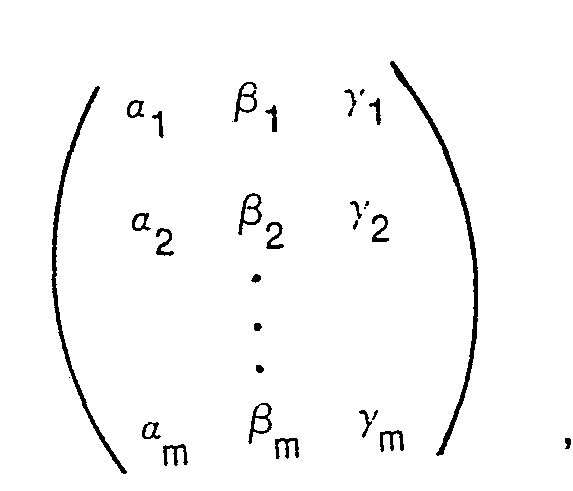
- this localisation be at the direction of the point (Re (X/W), Re (Y/W), Re (Z/W)), and in that case the signals S + i and S - i are given by: where ⁇ i , ⁇ i , ⁇ i , and ⁇ i are real coefficients, where jW' i is any signal having a 90° phase relation to W' for all sound directions, and where the 3 x m matrix: satisfies the matrix equation: where k is a positive constant and and is the 3 x 3 identity matrix and where ⁇ i are the arbitrary real coefficients of directional biasing signals.
- Equation (36) may alternatively be written as:
- the matrix M may be given by the equation: A matrix M satisfying Equation 36 yields correct localisation according to all major low frequency localisation theories provided that the constant k is chosen to ensure that: for encoded sounds.
- the constant k may be implemented by means of gain or shelf filter circuits affecting the signals X', Y', Z' and W' prior to the final output matrix circuitry, and additional changes of gain. phase response and frequency response may be applied to these signals, provided that all the signals are affected equally by these additional changes.
- Figure 4 indicates an irregular octahedral layout of six loudspeakers F, B, LU, LD, RU and RD placed at a distance r from a reference point and respectively disposed in front, behind, at an angle ⁇ above due left, at an angle ⁇ below due left, at an angle ⁇ above due right, and at an angle ⁇ below due right.
- the corresponding loudspeaker feed signals S + i , S - 1 , S + 2 , S - 3 , S + 3 , S - 2 are fed to the loudspeakers at ⁇ (x i , y i , z i ) where:
- Figure 5 illustrates a decoder for use in the case when the signal W has unit gain for sounds encoded from all directions in space, and where X, Y and Z have respective gains ⁇ 2 cos cos ⁇ , ⁇ 2 sin ⁇ cos ⁇ and ⁇ 2 sin ⁇ for sounds having source azimuth ⁇ measured anticlockwise from due front and source elevation ⁇ measured upwards from horizontal such as may occur in the decoders of certain four-channel encoding systems with full-sphere directionality.
- the signals W, X, Y and Z are produced from the received input signals by a WXYZ circuit 40.
- the W signal is applied to a type I shelf filter 42 while the X, Y and Z signals are applied to respective type II shelf filters 44, 46 and 48.
- the function of the shelf filters 42 to 48 is analogous to that of shelf filters 12, 14 and 16 of Figure 1 and the transition frequency between low and high frequency gains is preferably centred at about 350 Hz, the shelf filters of both types having unity gain at low frequencies while the type I shelf filter has gain ⁇ 2 and the type II shelf filters have gain ⁇ 2/3 at frequencies well above the transition frequencies.
- the ratio of gains of the type II shelf filters to the type I shelf filter may be considered to implement a part of the factor k referred to in Equations (41) and (42). In this case it will be seen that k is a frequency dependent gain.
- the X, Y and Z signal paths also include high-pass filters 50, 52 and 54 to compensate for sound field curvature due to finite loudspeaker distance as previously described.
- the X, Y and Z signal paths also include amplifiers 56, 58 and 60 applying respective gains I, II and III in order to implement matrix Equation 35.
- gains I, II and III are given by:
- the output signals in the Y and Z channels from the amplifiers 58 and 60 respectively are added by an addition circuit 62 to give the difference signals for the LU and RD pair of loudspeakers, and subtracted by a subtraction cirucit 64 to obtain the difference signal for the RU and LD pair of loudspeakers.
- Each of these difference signals is combined by a respective addition circuit 66, 68 and 70 to give the signals S;, S2, and S3 which are amplified by respective power amplifiers 72, 74 and 76 and fed through the loudspeakers F, LU and RU.
- the output signal in the W channel from the shelf filter 42 is also applied to an amplifier 78 having a gain of 2 and thence to a power amplifier 80 having equal gain to that of the power amplifiers 72, 74 and 76.
- Each of the signals S + 1 , S + 2 , and S + 3 is subtracted from the output of the amplifier 80 by connecting a respective one of the loudspeakers B, RD and LD between the output of the amplifier 80 and the output of the corresponding one of the amplifiers 72, 74 and 76.
- This so-called loudspeaker matrixing technique forms the subject of U.K. Patent Specification No. 1,548,674 and may also be applied to decoders for feeding horizontal loudspeaker arrays in accordance with the present invention, such as the decoder illustrated in Figures 2 and 3.
- the invention may also be applied to more complex irregular loudspeaker layouts.
- the invention may be applied to a three dimensional layout of eight loudspeakers LF, RF, LB, RB, LU, LD, RU and RD as shown in Figure 6, placed at the cartesian co-ordinates (x i , y i , z i ) and ( ⁇ x i , ⁇ y i , ⁇ z 1 ,) with respective feed signals S + i and S - i ; of the form given in Equations (33) and (34), where i has the values 1 to 4, and where, for radius r.
- Such a loudspeaker layout can be made to satisfy the directional requirements of the Makita and energy vector theories if one applies Equation (38) to the layout.
- a calculation shows that: so that the loudspeaker feed signals are given by Equations (33) and (34) by using these values of ⁇ i , ⁇ i , ⁇ i for a suitable positive gain k (which may be chosen to be frequency dependent).
- Figure 7 illustrates a decoder for use with a variety of three dimensional loudspeaker layouts in accordance with this invention, including those described above in reference to Figures 4 and 6.
- This decoder is also suitable for use with a cuboid of loudspeakers as described in U.K. Patent Specifications Nos. 1,494,751 and 1,494,752 and incorporates a WXYZ circuit 90, type I and II shelf filters 92, 94, 96 and 98 and also high-pass filters 100, 102 and 104 to compensate for loudspeaker distance as described in the aforementioned specifications.
- the decoder also incorporates a switchable amplitude matrix 114.
- variable gain amplifiers 106, 108, 110 and 112 By providing several variable gain amplifiers 106, 108, 110 and 112, and by making the output amplitude matrix coeffients switchable to match the type of loudspeaker layout chosen, a single decoder can be made which is suitable for a number of different loudspeaker layouts.
- the variable gain amplifiers permit adjustment of the angles ⁇ and ⁇ describing the exact shape of the loudspeaker layout and thus act as a "layout control".
- any of the decoders described above can be used in conjunction with additional gain and time delay circuitry which serves to modify the output signals from the decoder prior to feeding these to the loudspeakers in order to compensate for loudspeakers at unequal distances from the common reference point, in accordance with the provisions of U.K. Patent Specification No. 1,552,478.
- the designation of the x-axis as being “forward”, the y-axis as being “leftward” and the z-axis as being “upward” in this specification is purely arbitrary, and that x, y and z axes could equally as well be chosen to be any other set of 3 orthgonal cartesian axes at the common reference point.
- the decoders described with reference to Figures 3 to 6 will be suitable for alternative orientations of loudspeaker layouts.
- the L loudspeaker of Figure 3 will become a front loudspeaker
- the R loudspeaker will become a back loudspeaker
- the left front, left back, right front, right back loudspeakers will become respectively left front, right front, left back and right back loudspeakers.
- the octahedral layout of Figure 4 will consist of front and back vertical pairs of speakers and one loudspeaker at each side.
- the layout of Figure 6 will consist of front and back vertical pairs of loudspeakers and left and right side pairs of loudspeakers.
- amplitude matrix described above may also incorporate any additional overall gain (including phase inversion where appropriate) such as might be considered desirable by one skilled in the art.
Landscapes
- Physics & Mathematics (AREA)
- Engineering & Computer Science (AREA)
- Mathematical Physics (AREA)
- General Physics & Mathematics (AREA)
- Mathematical Analysis (AREA)
- Mathematical Optimization (AREA)
- Algebra (AREA)
- Pure & Applied Mathematics (AREA)
- Theoretical Computer Science (AREA)
- Acoustics & Sound (AREA)
- Signal Processing (AREA)
- Circuit For Audible Band Transducer (AREA)
- Stereophonic System (AREA)
- Obtaining Desirable Characteristics In Audible-Bandwidth Transducers (AREA)
Abstract
Claims (24)


Jour tous les sons directionnels codés dans les signaux W', X', Y' et Z'.


Applications Claiming Priority (2)
| Application Number | Priority Date | Filing Date | Title |
|---|---|---|---|
| GB8006174 | 1980-02-23 | ||
| GB8006174 | 1980-02-23 |
Publications (2)
| Publication Number | Publication Date |
|---|---|
| EP0046765A1 EP0046765A1 (fr) | 1982-03-10 |
| EP0046765B1 true EP0046765B1 (fr) | 1983-12-07 |
Family
ID=10511618
Family Applications (1)
| Application Number | Title | Priority Date | Filing Date |
|---|---|---|---|
| EP81900334A Expired EP0046765B1 (fr) | 1980-02-23 | 1981-02-12 | Systemes de reproduction des sons |
Country Status (7)
| Country | Link |
|---|---|
| US (1) | US4414430A (fr) |
| EP (1) | EP0046765B1 (fr) |
| JP (1) | JPH0712240B2 (fr) |
| DE (1) | DE3161567D1 (fr) |
| DK (1) | DK153269C (fr) |
| GB (1) | GB2073556B (fr) |
| WO (1) | WO1981002502A1 (fr) |
Families Citing this family (16)
| Publication number | Priority date | Publication date | Assignee | Title |
|---|---|---|---|---|
| US4799260A (en) * | 1985-03-07 | 1989-01-17 | Dolby Laboratories Licensing Corporation | Variable matrix decoder |
| US5274740A (en) * | 1991-01-08 | 1993-12-28 | Dolby Laboratories Licensing Corporation | Decoder for variable number of channel presentation of multidimensional sound fields |
| US5594800A (en) * | 1991-02-15 | 1997-01-14 | Trifield Productions Limited | Sound reproduction system having a matrix converter |
| GB9103207D0 (en) * | 1991-02-15 | 1991-04-03 | Gerzon Michael A | Stereophonic sound reproduction system |
| US5757927A (en) * | 1992-03-02 | 1998-05-26 | Trifield Productions Ltd. | Surround sound apparatus |
| CN1037891C (zh) * | 1992-06-11 | 1998-03-25 | 赵维援 | 多声道音频功率放大集成电路 |
| US5319713A (en) * | 1992-11-12 | 1994-06-07 | Rocktron Corporation | Multi dimensional sound circuit |
| US6118876A (en) * | 1995-09-07 | 2000-09-12 | Rep Investment Limited Liability Company | Surround sound speaker system for improved spatial effects |
| US5708719A (en) * | 1995-09-07 | 1998-01-13 | Rep Investment Limited Liability Company | In-home theater surround sound speaker system |
| US5930370A (en) * | 1995-09-07 | 1999-07-27 | Rep Investment Limited Liability | In-home theater surround sound speaker system |
| US6072878A (en) | 1997-09-24 | 2000-06-06 | Sonic Solutions | Multi-channel surround sound mastering and reproduction techniques that preserve spatial harmonics |
| EP1749420A4 (fr) * | 2004-05-25 | 2008-10-15 | Huonlabs Pty Ltd | Dispositif et procede audio |
| JP4886242B2 (ja) * | 2005-08-18 | 2012-02-29 | 日本放送協会 | ダウンミックス装置およびダウンミックスプログラム |
| US20120155650A1 (en) * | 2010-12-15 | 2012-06-21 | Harman International Industries, Incorporated | Speaker array for virtual surround rendering |
| EP2541547A1 (fr) | 2011-06-30 | 2013-01-02 | Thomson Licensing | Procédé et appareil pour modifier les positions relatives d'objets de son contenu dans une représentation ambisonique d'ordre supérieur |
| US9338552B2 (en) | 2014-05-09 | 2016-05-10 | Trifield Ip, Llc | Coinciding low and high frequency localization panning |
Family Cites Families (5)
| Publication number | Priority date | Publication date | Assignee | Title |
|---|---|---|---|---|
| GB1369813A (en) * | 1971-02-02 | 1974-10-09 | Nat Res Dev | Reproduction of sound |
| GB1494751A (en) * | 1974-03-26 | 1977-12-14 | Nat Res Dev | Sound reproduction systems |
| GB1550627A (en) * | 1975-11-13 | 1979-08-15 | Nat Res Dev | Sound reproduction systems |
| US4095049A (en) * | 1976-03-15 | 1978-06-13 | National Research Development Corporation | Non-rotationally-symmetric surround-sound encoding system |
| GB1548674A (en) * | 1976-07-01 | 1979-07-18 | Nat Res Dev | Sound reproduction systems |
-
1981
- 1981-02-04 GB GB8103405A patent/GB2073556B/en not_active Expired
- 1981-02-12 WO PCT/GB1981/000018 patent/WO1981002502A1/fr active IP Right Grant
- 1981-02-12 DE DE8181900334T patent/DE3161567D1/de not_active Expired
- 1981-02-12 JP JP56500548A patent/JPH0712240B2/ja not_active Expired - Lifetime
- 1981-02-12 EP EP81900334A patent/EP0046765B1/fr not_active Expired
- 1981-02-12 US US06/305,623 patent/US4414430A/en not_active Expired - Lifetime
- 1981-09-16 DK DK411381A patent/DK153269C/da not_active IP Right Cessation
Also Published As
| Publication number | Publication date |
|---|---|
| DK153269B (da) | 1988-06-27 |
| GB2073556B (en) | 1984-02-22 |
| DK153269C (da) | 1988-11-21 |
| EP0046765A1 (fr) | 1982-03-10 |
| WO1981002502A1 (fr) | 1981-09-03 |
| JPS57500268A (fr) | 1982-02-12 |
| GB2073556A (en) | 1981-10-14 |
| JPH0712240B2 (ja) | 1995-02-08 |
| US4414430A (en) | 1983-11-08 |
| DE3161567D1 (en) | 1984-01-12 |
| DK411381A (da) | 1981-09-16 |
Similar Documents
| Publication | Publication Date | Title |
|---|---|---|
| EP0046765B1 (fr) | Systemes de reproduction des sons | |
| US3997725A (en) | Multidirectional sound reproduction systems | |
| US5596644A (en) | Method and apparatus for efficient presentation of high-quality three-dimensional audio | |
| US9877131B2 (en) | Apparatus and method for enhancing a spatial perception of an audio signal | |
| US5610986A (en) | Linear-matrix audio-imaging system and image analyzer | |
| US5757927A (en) | Surround sound apparatus | |
| US6385320B1 (en) | Surround signal processing apparatus and method | |
| JPS6216080B2 (fr) | ||
| US8165326B2 (en) | Sound field control apparatus | |
| EP2070390B1 (fr) | Résolution spatiale améliorée du champ acoustique pour systèmes de lecture audio par dérivation de signaux à termes angulaires d'ordre supérieur | |
| GB1593662A (en) | Microphone system for producing signals for quadraphonic reproduction | |
| KR20200126429A (ko) | 라우드스피커를 위한 다중 채널 부대역 공간 처리 기법 | |
| EP0629335B1 (fr) | Appareil de reproduction de son d'ambiance | |
| US3824342A (en) | Omnidirectional sound field reproducing system | |
| US4086433A (en) | Sound reproduction system with non-square loudspeaker lay-out | |
| US4095049A (en) | Non-rotationally-symmetric surround-sound encoding system | |
| GB2045586A (en) | Microphone system | |
| US20110216906A1 (en) | Enabling 3d sound reproduction using a 2d speaker arrangement | |
| JPS6131680B2 (fr) | ||
| JP2022551871A (ja) | マルチチャネルクロストーク処理 | |
| US5982905A (en) | Distortion reduction in signal processors | |
| US20220279272A1 (en) | Mid Dual-Side Microphone | |
| WO2024105825A1 (fr) | Système de lecture audio | |
| JP2000165980A (ja) | マイクロホン装置及び指向性制御装置 | |
| JP3186909B2 (ja) | ビデオカメラ用ステレオマイクロホン |
Legal Events
| Date | Code | Title | Description |
|---|---|---|---|
| PUAI | Public reference made under article 153(3) epc to a published international application that has entered the european phase |
Free format text: ORIGINAL CODE: 0009012 |
|
| 17P | Request for examination filed |
Effective date: 19811008 |
|
| AK | Designated contracting states |
Designated state(s): DE FR NL |
|
| GRAA | (expected) grant |
Free format text: ORIGINAL CODE: 0009210 |
|
| AK | Designated contracting states |
Designated state(s): DE FR NL |
|
| REF | Corresponds to: |
Ref document number: 3161567 Country of ref document: DE Date of ref document: 19840112 |
|
| ET | Fr: translation filed | ||
| PLBE | No opposition filed within time limit |
Free format text: ORIGINAL CODE: 0009261 |
|
| STAA | Information on the status of an ep patent application or granted ep patent |
Free format text: STATUS: NO OPPOSITION FILED WITHIN TIME LIMIT |
|
| 26N | No opposition filed | ||
| PGFP | Annual fee paid to national office [announced via postgrant information from national office to epo] |
Ref country code: FR Payment date: 19920127 Year of fee payment: 12 |
|
| PGFP | Annual fee paid to national office [announced via postgrant information from national office to epo] |
Ref country code: NL Payment date: 19920229 Year of fee payment: 12 |
|
| REG | Reference to a national code |
Ref country code: FR Ref legal event code: TP |
|
| NLS | Nl: assignments of ep-patents |
Owner name: BRITISH TECHNOLOGY GROUP LTD TE LONDEN, GROOT-BRIT |
|
| PG25 | Lapsed in a contracting state [announced via postgrant information from national office to epo] |
Ref country code: NL Effective date: 19930901 |
|
| NLV4 | Nl: lapsed or anulled due to non-payment of the annual fee | ||
| PG25 | Lapsed in a contracting state [announced via postgrant information from national office to epo] |
Ref country code: FR Effective date: 19931029 |
|
| REG | Reference to a national code |
Ref country code: FR Ref legal event code: ST |
|
| PGFP | Annual fee paid to national office [announced via postgrant information from national office to epo] |
Ref country code: DE Payment date: 19991231 Year of fee payment: 20 |