EP0046592A2 - Luftevakuierungsvorrichtung für mit Lebensmittel gefüllte Beutel - Google Patents
Luftevakuierungsvorrichtung für mit Lebensmittel gefüllte Beutel Download PDFInfo
- Publication number
- EP0046592A2 EP0046592A2 EP81106586A EP81106586A EP0046592A2 EP 0046592 A2 EP0046592 A2 EP 0046592A2 EP 81106586 A EP81106586 A EP 81106586A EP 81106586 A EP81106586 A EP 81106586A EP 0046592 A2 EP0046592 A2 EP 0046592A2
- Authority
- EP
- European Patent Office
- Prior art keywords
- tube
- nozzle member
- end portion
- open end
- outer nozzle
- Prior art date
- Legal status (The legal status is an assumption and is not a legal conclusion. Google has not performed a legal analysis and makes no representation as to the accuracy of the status listed.)
- Granted
Links
Images


Classifications
-
- B—PERFORMING OPERATIONS; TRANSPORTING
- B65—CONVEYING; PACKING; STORING; HANDLING THIN OR FILAMENTARY MATERIAL
- B65B—MACHINES, APPARATUS OR DEVICES FOR, OR METHODS OF, PACKAGING ARTICLES OR MATERIALS; UNPACKING
- B65B31/00—Packaging articles or materials under special atmospheric or gaseous conditions; Adding propellants to aerosol containers
- B65B31/04—Evacuating, pressurising or gasifying filled containers or wrappers by means of nozzles through which air or other gas, e.g. an inert gas, is withdrawn or supplied
- B65B31/06—Evacuating, pressurising or gasifying filled containers or wrappers by means of nozzles through which air or other gas, e.g. an inert gas, is withdrawn or supplied the nozzle being arranged for insertion into, and withdrawal from, the mouth of a filled container and operating in conjunction with means for sealing the container mouth
Definitions
- This invention relates to a deaerator for use in vacuum packaging a one-end-bond tubular film consisting of a thermally contractible synthetic resin and filled with food, for example, ham or a sausage, by removing the air, which remains in the tube, from an open end portion thereof thoroughly, and thereafter binding the open end portion of the same tube.
- Removing the residual air thoroughly from a tube containing, especially, food is essential to the maintenance of the quality thereof.
- a 100% removal of the residual air from such a tube can be effectively carried out only when a deaerating operation for the tube has been shifted smoothly to a binding operation for an open end portion thereof.
- an open end portion of a tube is gathered or drawn to the center of a cross section thereof before the open end portion of the tube has been bound.
- a deaeration nozzle is then inserted into the gathered end portion of the tube to remove the residual air therefrom.
- the deaeration nozzle be removed to the outside of the tube so as to allow a gathered end-binding operation to be conducted simultaneously.
- the outside air would enter the tube to reside therein after the gathered end portion of the tube has been bound.
- This binding means includes a greatly extended end portion of a food-inserted tube, which end portion is gathered at two axially spaced regions thereof.
- a deaeration nozzle is inserted into the tube to remove the residual air therefrom, and the deaeration nozzle is thereafter removed from the inner gathered portion alone of the tube with the deaeration nozzle left inserted through the outer gathered portion thereof.
- the inner gathered portion of the tube is then bound as the deaeration of the tube is kept being carried out.
- This improvement permits deaerating a food-inserted tube perfectly.
- a film tube of as long as not less than 10cm is left over as a chip. Accordingly, when the above improvement is applied to the mass production of such a vacuum- packaged food, tube chips are accumulated in the workshop. The wasting of material as mentioned above causes the cost of manufacturing tube-wrapped food to be increased.
- An object of the present invention is to eliminate the above-mentioned drawbacks encountered in a conventional device of this kind.
- Another object of the present invention is to provide a novel device which permits deaerating a food-inserted one-end-bound tube perfectly with a film tube of as short as only l-2cm left over as a chip when an excess section of a gathered end portion, which has been bound, of the tube is cut off.
- a double deaeration nozzle consisting of concentrically arranged inner and outer members is provided in such a manner that the inner nozzle member can be projected out of and retracted-into the outer nozzle member.
- the inner nozzle member is retracted into the outer nozzle member to allow the tube to be continuously deaerated via the outer nozzle member even after the inner nozzle member has been retracted thereinto.
- an auxiliary deaerating means for use in thermally contracting a bottom portion of a food-inserting tube to remove the residual air from the tube perfectly and thereby further improve the tube-end binding effect.
- the present invention provides a deaerator for food-inserted one-end-bound tubes, comprising a double deaeration nozzle which is provided in a position opposed to a gathered open end portion of a food-inserted one-end-bound tube and which consists of concentrically arranged inner and outer nozzle members; an actuator means for use in displacing the inner nozzle member between a position in which the inner nozzle member is projected from the front end of the outer nozzle member and a position in which the inner nozzle member is retracted in the outer nozzle member; a means for connecting the open end portion of the tube to the nozzle, which means is adapted to extend the open end portion of the tube onto the outer circumferential surface of the outer nozzle member and cover the latter with the former when the inner nozzle member is projected from the front end of the outer nozzle member; a tube-end gathering mechanism disposed so as to work on that section of the open end portion of the tube which is extended around the projected portion of the inner nozzle member; and a tube-end
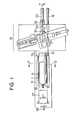
- Fig. 1 is a plan view of the device as a whole according to the present invention.
- a single- or multilayer tube 7 which consists of a thermally contractible synthetic resin, such as saran film and which contains ham 8, has been transferred onto a working table 10 by a transfer means (not shown) with a tube bottom 9 having already been gathered and bound in another place.
- a vertically movable piston rod 11 is joined to the lower surface of the working table 10 as shown in Fig. 2.
- an air cylinder (not shown) is actuated, and the rod 11 is moved upqardly along a guide 12 to lift the working table 10 up to the upper end of a wall 13, so that a product is rolled along an inclined wall 14 to-be carried out of the apparatus.
- a piston rod 15 for use in forwardly and backwardly moving the working table 10 is joined to the guide 12 for the rod 11, which piston rod 15 is extended in the direction of the length of the working table 10 and moved forwardly and backwardly by an operation of an air cylinder 16 shown in Fig. 1, with the assistance of a guide roller 17.
- FIG. 5 An example of a mechanism for gathering an open end portion of a ham-inserted tube and binding the gathered end portion of the tube with a clip is shown in Fig. 5.
- This mechanism is provided with machine frames 19, 20 disposed in an opposed relationship, and a pair of regulating elements 21, 22, which are extended parallel to each other and at right angles to the machine frames 19, 20 in such a manner that the regulating elements 21, 22 can be displaced along the machine frames 19, 20.
- the machine frames 19, 20 and regulating elements 21, 22 define a rectangular space. When the regulating elements 21, 22 are in their opened positions, the circularly opened end portion 7a is inserted into the rectangularly opened space mentioned above.
- An inner nozzle member 24 of a double deaeration nozzle, a part of the deaerator according to the present invention, consisting of two concentrically arranged nozzle members 23, 24 is projected into the central portion of the above-mentioned rectangularly opened space, and in opposition to the open end portion 7a of the ham-inserted tube 7.
- the nozzle 24 is enclosed therewith.
- the forward movement of the open end portion 7a of the tube 7 is detected by a sensor (not shown).
- the regulating elements 21, 22 are actuated at once by operations of air cylinders (not shown).
- the regulating elements 21, 22 are moved toward each other from positions of two-dot chain line in Fig. 5 and stopped in positions of solid line in the same drawing, in which the regulating elements 21, 22 are close to each other with a gap 25 left therebetween.
- the gap 25 has a width equal to that of each of folds to be formed on the open end portion 7a when it is gathered.
- a pair of gather-binding elements 26, 27, which are provided in an opposed relationship in bores in the central portions of the opposed machine frames 19, 20, respectively, are moved, by operations of air cylinders (not shown), toward each other along the gap 25 between the regulating elements 21, 22.
- the elongated half-opened end portion 7a of the tube 7 is gathered in the central portion of the gap 25, and pressed against the outer circumferential surface of the inner nozzle member 24 as the inner nozzle member 24 is enclosed with the end portion 7a.
- Each of the gather-binding elements 26, 27 has a recess in an end portion thereof.
- a clip (not shown) is bent by the pressing effect of these recesses provided in the gather-binding elements 26, 27, so that the end portion 7a is finally bound. Since this tube-end binding operation is out of the gist of the present invention, a description thereof will be omitted. A perfect deaeration of a ham-inserted tube, which constitutes a step to be carried out immediately before a tube end-binding operation, will be described in detail.
- each of the gather-binding elements 26, 27 is provided on its right and left sides with elastic pads 28, 29, by which the end portion 7a of the tube 7 is pressed against the outer circumferential surfaces of the inner and outer nozzle members 24, 23. It is necessary that each of the elastic pads 29, out of the pads 28, 29, be used to press at the greater part of the lower surface thereof the end portion 7a of the tube 7 against the outer circumferential surface of the outer nozzle member 23. Thus, the connection of the outer end 7a of the tube 7 and the inner and outer nozzle members 24, 23 is completed.
- the outer nozzle member 23, one of the concentrically arranged inner and outer nozzle members 24, 23 is fixed to a machine frame 30 at a rear end portion thereof, and connected to a vacuum pump (not shown) via an air discharge pipe 31. While a deaerating operation for a ham-inserted tube 7 is conducted, the inner nozzle member 24 is extended at a front end portion thereof out of the outer nozzle member 23 (refer to Figs. 3 and 6) as the nozzle member 24 maintains a narrow gap between the outer circumferential surface thereof and the inner circumferential surface of the outer nozzle member 23. While a tube-end binding operation is conducted, the inner nozzle member 24 is retracted into the outer nozzle member 23 (refer to Fig. 4).
- the inner nozzle member 24 is connected at a rear end portion thereof to a piston rod 34, which is adapted to be displaced forwardly and backwardly by an operation of an air cylinder 33 provided on a bracket 32 connected to the machine frame 30.
- the inner nozzle member 24 is communicated with a vacuum pump (not shown) via a discharge pipe 35.
- an electric heater 37 is provided behind the working table 10, the electric heater 37 being directed to the tube bottom 9 which has already been bound.
- a blower 36 is provided behind the electric heater 37.
- An air current sent from the blower 36 to the tube bottom 9 is heated when it passes through the heater 37, so that hot air is applied to the tube bottom 9.
- the tube bottom 9 exposed to the hot air is thermally contracted to cause the residual air therein to be sent to the open end portion 7a of the tube 7.
- the residual air sent to the open end portion 7a is sucked by the inner and outer nozzle members 24, 23 to be discharged outside.
- the inner nozzle member 24 of the double nozzle is projected from the front end of the outer nozzle member 23 (refer to Figs. 3 and 6) by an operation of the air cylinder 33.
- the outer circumferential surface of the inner nozzle member 24 thus projected from the outer nozzle member 23 and the outer circumferential surface of the outer nozzle member 23 are covered with the end portion 7a, so that the end portion 7a and the double nozzle are connected together.
- the inner nozzle member 24 projected from the outer nozzle member 23 obstructs a tube-end binding operation, which is conducted after the deaeration of the tube 7 has been completed. Accordingly, the inner nozzle member 24 is retracted, before a tube-end binding operation has been conducted, into the outer nozzle member 23 by an operation of the air cylinder 33 via the piston rod 34.
- the gather-binding elements 26, 27 are then applied at their respective free end surfaces to the end portion 7a as shown in Fig. 4, to seal the tube 7 with a clip (not shown).
- the deaeration of a ham-inserted tube during such a short period of time as mentioned above is not satisfactorily carried out by a conventional deaerator of this kind.
- the outside air enters the tube, which has once been deaerated sufficiently, during a short period of time referred to above.
- a tube-end binding operation with conventional deaerator and gather-binding elements is carried out under the above-mentioned condition.
- the outer nozzle member 23 is still in close contact with the end portion 7a of the tube 7 even after the inner nozzle member 24 has been retracted (refer to Fig. 4), so that the tube 7 is still subjected to deaeration.
- a tube-end binding operation is conducted under such condition, so that the outside air does not enter the tube during a tube-end binding operation.
- the tube is sealed in a perfectly deaerated state. Therefore, a decrease in the quality of a ham product due to the residual air in the tube in which the product is sealed can be completely eliminated.
- the above effect of the present invention has been achieved by the concentrically arranged deaeration nozzles 23, 24. ' Accordingly, an elongated end portion 7a is not required.
- the length of a tube left over as a chip after a ham-sealed tube with the end portions thereof bound has been subjected to a cutting operation for an excess portion thereof is as short as 1-2cm. This contributes to the nursing of resorces, and results in a decrease in the cost of manufacturing packaged ham products. Consequently, low- priced, high-quality packaged ham products can be supplied to the consumers.
Priority Applications (1)
| Application Number | Priority Date | Filing Date | Title |
|---|---|---|---|
| AT81106586T ATE10353T1 (de) | 1980-08-26 | 1981-08-25 | Luftevakuierungsvorrichtung fuer mit lebensmittel gefuellte beutel. |
Applications Claiming Priority (2)
| Application Number | Priority Date | Filing Date | Title |
|---|---|---|---|
| JP55117340A JPS5746714A (en) | 1980-08-26 | 1980-08-26 | Deaerator in bag mouth |
| JP117340/80 | 1980-08-26 |
Publications (3)
| Publication Number | Publication Date |
|---|---|
| EP0046592A2 true EP0046592A2 (de) | 1982-03-03 |
| EP0046592A3 EP0046592A3 (en) | 1982-03-17 |
| EP0046592B1 EP0046592B1 (de) | 1984-11-21 |
Family
ID=14709278
Family Applications (1)
| Application Number | Title | Priority Date | Filing Date |
|---|---|---|---|
| EP81106586A Expired EP0046592B1 (de) | 1980-08-26 | 1981-08-25 | Luftevakuierungsvorrichtung für mit Lebensmittel gefüllte Beutel |
Country Status (7)
| Country | Link |
|---|---|
| EP (1) | EP0046592B1 (de) |
| JP (1) | JPS5746714A (de) |
| KR (1) | KR830006071A (de) |
| AT (1) | ATE10353T1 (de) |
| AU (1) | AU7435981A (de) |
| DE (1) | DE3167323D1 (de) |
| ZA (1) | ZA815789B (de) |
Cited By (5)
| Publication number | Priority date | Publication date | Assignee | Title |
|---|---|---|---|---|
| DE3834524A1 (de) * | 1987-10-20 | 1989-05-03 | Or Ve D S A S Di Salvaro Marzi | Geraet fuer die vakuumverpackung von gegenstaenden in flexiblen beuteln oder huellen |
| EP0734951A2 (de) * | 1995-03-31 | 1996-10-02 | Eastman Kodak Company | Vorrichtung und Verfahren zum Vakuumsiegeln von Beuteln |
| US5667627A (en) * | 1995-08-15 | 1997-09-16 | The United States Of America As Represented By The Secretary Of The Navy | Hand held vacuum heat sealer apparatus |
| US5737906A (en) * | 1996-02-01 | 1998-04-14 | Zaidan Houjin Shinku Kagaku | Quick pressure reducing apparatus |
| EP1057729A1 (de) * | 1996-09-17 | 2000-12-06 | Molins Plc | Vorrichtung und Verfahren zum Herstellen von gesiegelten Verpackungen |
Citations (4)
| Publication number | Priority date | Publication date | Assignee | Title |
|---|---|---|---|---|
| GB645802A (en) * | 1947-11-26 | 1950-11-08 | Dewey And Almy Chem Comp | Packaging machine |
| FR1192587A (fr) * | 1958-02-28 | 1959-10-27 | Perfectionnements aux dispositifs permettant la mise sous vide et la fermeture de sachets, étuis ou analogues en matière plastique | |
| US3700387A (en) * | 1971-04-26 | 1972-10-24 | Kartridg Pak Co | Vacuum bagging machine |
| US3796020A (en) * | 1972-06-22 | 1974-03-12 | Armour & Co | Device for closing a bag under vacuum |
-
1980
- 1980-08-26 JP JP55117340A patent/JPS5746714A/ja active Pending
-
1981
- 1981-08-18 KR KR1019810002991A patent/KR830006071A/ko unknown
- 1981-08-20 AU AU74359/81A patent/AU7435981A/en not_active Abandoned
- 1981-08-21 ZA ZA815789A patent/ZA815789B/xx unknown
- 1981-08-25 DE DE8181106586T patent/DE3167323D1/de not_active Expired
- 1981-08-25 EP EP81106586A patent/EP0046592B1/de not_active Expired
- 1981-08-25 AT AT81106586T patent/ATE10353T1/de not_active IP Right Cessation
Patent Citations (4)
| Publication number | Priority date | Publication date | Assignee | Title |
|---|---|---|---|---|
| GB645802A (en) * | 1947-11-26 | 1950-11-08 | Dewey And Almy Chem Comp | Packaging machine |
| FR1192587A (fr) * | 1958-02-28 | 1959-10-27 | Perfectionnements aux dispositifs permettant la mise sous vide et la fermeture de sachets, étuis ou analogues en matière plastique | |
| US3700387A (en) * | 1971-04-26 | 1972-10-24 | Kartridg Pak Co | Vacuum bagging machine |
| US3796020A (en) * | 1972-06-22 | 1974-03-12 | Armour & Co | Device for closing a bag under vacuum |
Cited By (8)
| Publication number | Priority date | Publication date | Assignee | Title |
|---|---|---|---|---|
| DE3834524A1 (de) * | 1987-10-20 | 1989-05-03 | Or Ve D S A S Di Salvaro Marzi | Geraet fuer die vakuumverpackung von gegenstaenden in flexiblen beuteln oder huellen |
| GB2211161A (en) * | 1987-10-20 | 1989-06-28 | Or Ve D S A S Di Salvaro Marzi | Apparatus for vacuum-packaging articles in flexible bags |
| EP0734951A2 (de) * | 1995-03-31 | 1996-10-02 | Eastman Kodak Company | Vorrichtung und Verfahren zum Vakuumsiegeln von Beuteln |
| EP0734951A3 (de) * | 1995-03-31 | 1997-01-02 | Eastman Kodak Co | Vorrichtung und Verfahren zum Vakuumsiegeln von Beuteln |
| US5667627A (en) * | 1995-08-15 | 1997-09-16 | The United States Of America As Represented By The Secretary Of The Navy | Hand held vacuum heat sealer apparatus |
| US5737906A (en) * | 1996-02-01 | 1998-04-14 | Zaidan Houjin Shinku Kagaku | Quick pressure reducing apparatus |
| EP1057729A1 (de) * | 1996-09-17 | 2000-12-06 | Molins Plc | Vorrichtung und Verfahren zum Herstellen von gesiegelten Verpackungen |
| US6543206B2 (en) * | 1996-09-17 | 2003-04-08 | Molins Plc | Apparatus and method for formation of sealed packages |
Also Published As
| Publication number | Publication date |
|---|---|
| JPS5746714A (en) | 1982-03-17 |
| DE3167323D1 (en) | 1985-01-03 |
| EP0046592A3 (en) | 1982-03-17 |
| ATE10353T1 (de) | 1984-12-15 |
| AU7435981A (en) | 1982-03-04 |
| KR830006071A (ko) | 1983-09-17 |
| EP0046592B1 (de) | 1984-11-21 |
| ZA815789B (en) | 1982-08-25 |
Similar Documents
| Publication | Publication Date | Title |
|---|---|---|
| DE2404038C2 (de) | Vorrichtung zum Vakuumverpacken eines Produkts in einem flexiblen Behälter | |
| CA1299085C (en) | Form-fill-seal machine and method with capability for providing a vacuumor inert gas atmosphere within the package | |
| ES2060278T3 (es) | Un mecanismo desmoldeador para maquinas de empaquetar con bolsa tubular. | |
| US3597895A (en) | Packaging method and machine | |
| IE65890B1 (en) | Packing machine | |
| EP0046592A2 (de) | Luftevakuierungsvorrichtung für mit Lebensmittel gefüllte Beutel | |
| US5511363A (en) | Vertical cyclically operating flat sack machine | |
| EP1371556B1 (de) | Verfahren und Vorrichtung zur Entlüftung für eine Beutelfüllmaschine | |
| KR19990044136A (ko) | 포장장치 | |
| US6079469A (en) | Transverse seam sealing device for a bag forming and filling machine | |
| US3700387A (en) | Vacuum bagging machine | |
| KR19990076982A (ko) | 포장장치에서의 시일장치 | |
| US1944147A (en) | Bag making and filling machine | |
| US4344270A (en) | Method and apparatus for packaging commodities | |
| GB2065591A (en) | Applying open-topped bags to a filling nozzle and compressing a substance dispensed into the bags | |
| US3796020A (en) | Device for closing a bag under vacuum | |
| JP2640923B2 (ja) | 充填包装機における2段階シール装置 | |
| CN110914159B (zh) | 用于操作用热塑性膜包装产品的机器的工艺 | |
| CA1161806A (en) | Deaerator for food-inserted one-end-bond tubes | |
| US3579404A (en) | Cutting and sealing unit | |
| JPS5933765Y2 (ja) | 袋口における脱気装置 | |
| US3187481A (en) | Sealing apparatus | |
| JPH0236443B2 (de) | ||
| GB2211161A (en) | Apparatus for vacuum-packaging articles in flexible bags | |
| US3407989A (en) | Bag closure |
Legal Events
| Date | Code | Title | Description |
|---|---|---|---|
| PUAI | Public reference made under article 153(3) epc to a published international application that has entered the european phase |
Free format text: ORIGINAL CODE: 0009012 |
|
| PUAL | Search report despatched |
Free format text: ORIGINAL CODE: 0009013 |
|
| AK | Designated contracting states |
Designated state(s): AT BE CH DE FR GB IT LU NL SE |
|
| AK | Designated contracting states |
Designated state(s): AT BE CH DE FR GB IT LU NL SE |
|
| 17P | Request for examination filed |
Effective date: 19820914 |
|
| ITF | It: translation for a ep patent filed |
Owner name: STUDIO INGG. FISCHETTI & WEBER |
|
| GRAA | (expected) grant |
Free format text: ORIGINAL CODE: 0009210 |
|
| AK | Designated contracting states |
Designated state(s): AT BE CH DE FR GB IT LI LU NL SE |
|
| PG25 | Lapsed in a contracting state [announced via postgrant information from national office to epo] |
Ref country code: SE Effective date: 19841121 Ref country code: LI Effective date: 19841121 Ref country code: CH Effective date: 19841121 Ref country code: BE Effective date: 19841121 Ref country code: AT Effective date: 19841121 |
|
| REF | Corresponds to: |
Ref document number: 10353 Country of ref document: AT Date of ref document: 19841215 Kind code of ref document: T |
|
| REF | Corresponds to: |
Ref document number: 3167323 Country of ref document: DE Date of ref document: 19850103 |
|
| ET | Fr: translation filed | ||
| ET3 | Fr: translation filed ** decision concerning opposition | ||
| REG | Reference to a national code |
Ref country code: CH Ref legal event code: PL |
|
| PG25 | Lapsed in a contracting state [announced via postgrant information from national office to epo] |
Ref country code: LU Free format text: LAPSE BECAUSE OF NON-PAYMENT OF DUE FEES Effective date: 19850831 |
|
| PLBE | No opposition filed within time limit |
Free format text: ORIGINAL CODE: 0009261 |
|
| STAA | Information on the status of an ep patent application or granted ep patent |
Free format text: STATUS: NO OPPOSITION FILED WITHIN TIME LIMIT |
|
| 26N | No opposition filed | ||
| PG25 | Lapsed in a contracting state [announced via postgrant information from national office to epo] |
Ref country code: NL Effective date: 19860301 |
|
| GBPC | Gb: european patent ceased through non-payment of renewal fee | ||
| NLV4 | Nl: lapsed or anulled due to non-payment of the annual fee | ||
| PG25 | Lapsed in a contracting state [announced via postgrant information from national office to epo] |
Ref country code: FR Free format text: LAPSE BECAUSE OF NON-PAYMENT OF DUE FEES Effective date: 19860430 |
|
| PG25 | Lapsed in a contracting state [announced via postgrant information from national office to epo] |
Ref country code: DE Effective date: 19860501 |
|
| REG | Reference to a national code |
Ref country code: FR Ref legal event code: ST |
|
| PG25 | Lapsed in a contracting state [announced via postgrant information from national office to epo] |
Ref country code: GB Effective date: 19881118 |