EP0046427B1 - Dispositif de liage pour presses à balles cylindriques - Google Patents
Dispositif de liage pour presses à balles cylindriques Download PDFInfo
- Publication number
- EP0046427B1 EP0046427B1 EP81401262A EP81401262A EP0046427B1 EP 0046427 B1 EP0046427 B1 EP 0046427B1 EP 81401262 A EP81401262 A EP 81401262A EP 81401262 A EP81401262 A EP 81401262A EP 0046427 B1 EP0046427 B1 EP 0046427B1
- Authority
- EP
- European Patent Office
- Prior art keywords
- press
- controlling wheel
- bands
- guide
- wheel
- Prior art date
- Legal status (The legal status is an assumption and is not a legal conclusion. Google has not performed a legal analysis and makes no representation as to the accuracy of the status listed.)
- Expired
Links
Images

Classifications
-
- A—HUMAN NECESSITIES
- A01—AGRICULTURE; FORESTRY; ANIMAL HUSBANDRY; HUNTING; TRAPPING; FISHING
- A01F—PROCESSING OF HARVESTED PRODUCE; HAY OR STRAW PRESSES; DEVICES FOR STORING AGRICULTURAL OR HORTICULTURAL PRODUCE
- A01F15/00—Baling presses for straw, hay or the like
- A01F15/08—Details
- A01F15/14—Tying devices specially adapted for baling presses
- A01F15/141—Tying devices specially adapted for baling presses for round balers
Definitions
- the present invention relates to cylindrical balers.
- presses are of a well-known general type and comprise at least one set of bands or belts which, by their displacement, form by winding inside a chamber formed in the body of the press a ball of generally cylindrical shape. from harvested products, especially fodder or hay, picked up on the field during the progress of the machine. It is usual, before unloading the cylindrical bale from the press, to ensure its binding.
- This operation which is carried out using a link generally consisting of a string, is carried out in known manner by means of a device comprising a string guide moved transversely to the direction of operation of the press, generally in front of the inlet port in this press for products harvested from the field.
- the string is taken from an appropriate reserve and joins this guide before entering the press.
- When its end reaches this product entry interval it is gripped by the product sheet and wound around the bale under the effect of the rotation of the latter between the strips or belts, this winding movement combining to a distribution of the twists of string thus formed over the length of the bale, due to the transverse scanning movement of the guide.
- the existing guiding devices are in many cases relatively complicated and consequently a high cost price.
- the object of the invention is to create a device for controlling the transverse movement of the guide guide relative to the press which is of a simple and robust arrangement, and at the same time of reliable operation.
- the invention also aims to remedy these drawbacks.
- a binding device for cylindrical balers of the type comprising at least one set of bands or belts delimiting, inside the press, a chamber for winding the harvested products for the formation of a cylindrical bale, and a rectilinear guide disposed transversely to the press in the vicinity of the entry orifice of the tying twine in this chamber and on which a support carrying a twine guide can move, characterized in that a wheel director can be brought into contact with the set of bands is mounted on this support, this wheel being orientable relative to said support and thus, to the longitudinal axis of the press to cause, by contact with the bands or belts, a displacement of this support for the steering wheel and with it the guide guide on this transverse guide, for tying the bale.
- the contact of the steerable steering wheel with one of the sets of bands causes in an extremely simple and reliable manner the required displacement of the support and the string guide over the width of the press, without having to use any means of additional training.
- the transverse guide can be arranged judiciously in the vicinity of the upper guide rollers of these sets of bands or belts, the tying twine then passing between said rollers for its penetration into the press chamber.
- Each set of belts generally comprises at least one movable deflection roller which moves in accordance with the increase in diameter of the bale and which is usually carried by pivoting arms.
- the transverse guide is formed by a bar carried by the arms of the press serving to support the movable roller of at least one of sets of belts or bands.
- the support of the steering wheel can then be slidably mounted on this bar or on the transverse guide for example by a linear ball guide or by similar means, in order to be able to move back and forth transversely to the press. .
- the steering wheel is rotatably mounted in a yoke or the like, which can pivot around a generally vertical axis in a bearing slidably connected to the transverse bar forming a guide.
- This assembly thus allows the orientation of the steering wheel and consequently the control of its transverse movement along the guide relative to the press, the speed of transverse displacement being a function of the angle formed between the plane of this steering wheel and the longitudinal direction of the press.
- a tension spring mounted between an element integral with the yoke carrying this steering wheel and a fixed point of the support, which thus ensures the desired maintenance of this wheel in each of the required positions on either side of a neutral point.
- an arm connected to the steering wheel or to the yoke or the like in which it is mounted serves as an attachment point for a rope or an equivalent member which is directed forward. by crossing a guide located on the median longitudinal axis of the press.
- This rope can then be actuated by the driver of the tractor to which the press is coupled when the steering wheel is at the end of its travel during its transverse movement.
- other means such as simple stops can be provided for this command.
- the steering wheel is combined with a roller or other pressure member and the string used for binding passes between this wheel and this roller.
- the steering wheel is then judiciously equipped with a free wheel system to simply allow it to rotate in the direction corresponding to the penetration of the string into the press. It is thus used to maintain the twine between tying operations.
- the steering wheel is liftably mounted, so as to be brought into contact with the bands or belts for forming the bale only at the time of binding.
- the bar forming a transverse guide can be pivotally mounted, means being provided for locking it in the raised position.
- the control of the raising and lowering of the steering wheel can then be ensured for example by means of the aforementioned rope serving to reverse the orientation of the steering wheel at the end of the stroke during the transverse movement, or by means providing an equivalent function.
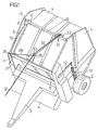
- FIG. 1 a cylindrical baler of conventional type comprising a body 1 supported by a chassis equipped with wheels 2, the press being intended to be coupled to a tractor by means of a drawbar 3.
- a pickup indicated schematically at 4 is provided so conventional to the front part of the body 1 of the press, so as to collect the harvested products, such as fodder, on the field and bring them to the orifice for the entry of the products into the press, formed between rollers one of which is visible at 5 in FIG. 1.
- each set of bands 6, 7 is movable and moves as a function of the increase in diameter of the bale during the formation thereof.
- the upper movable rollers of each set of bands 6, 7 have been designated by the references 8 and 9.
- these movable rollers are carried by arms 10 which are wedged on a transverse shaft 11 pivotally mounted in the body of the machine.
- This shaft carries at at least one end an arm 12 subjected to the action of a return spring 13, in a manner known per se.
- the ball which forms in the press chamber repels the belts 6, 7 due to the increase in its diameter and causes the displacement of the movable rollers 8, 9 and with them arms 10 in opposition to the action of the spring. recall 13.
- a transverse bar 14 extends between lugs 15 carried by the arms 10.
- this bar 14 is provided along its length with a rib 16 and it receives a support generally designated by the reference 17, this support comprising a sleeve 18 adapted on the bar 14 and being able to move thereon by a linear ball guide for example.
- a support generally designated by the reference 17
- this support comprising a sleeve 18 adapted on the bar 14 and being able to move thereon by a linear ball guide for example.
- the internal bore of the sleeve 18 has a groove adapted on the groove 16, so that said sleeve is angularly integral with the bar 14.
- a bearing 19 rigidly connected to the sleeve 18 to form the support 17 has a vertical bore in which can pivot the tail 20 of a yoke 21 directed downwards.
- This yoke is used for mounting a steering wheel 22 and a roller 23.
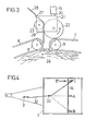
- the steering wheel 22 is judiciously provided with a free wheel system, so that it can simply turn in the direction indicated. by the arrow in Fig. 3 for a reason which will be set out below.
- the roller 23 is advantageously made of rubber.
- the tail 20 of the yoke carries at its upper end an arm 24, and a tension spring 25 is mounted between this arm and a lug 26 integral with the sleeve 18.
- the spring 25 acts accordingly to pivot the arm 24 and with it the yoke 21 and the steering wheel 22 in the vertical bearing 19, on either side of a neutral position in which this spring would be aligned with the horizontal branch of the arm 24.
- the degree of pivoting in one direction and in the other is limited by adjustable stops (not shown), which allows the angular position of the steering wheel 22 to be adjusted at will relative to a plane perpendicular to the bar 14.
- the yoke 21 also carries a guide eyelet 27 for the passage of the string 28 as visible in FIG. 3, as well as a knife 29 whose function will be indicated below.
- the bar 14 carries towards one end a toothed sector 30 angularly fixed on it and able to cooperate with a pawl 31 which is free to rotate.
- a rope 32 is attached to the arm 24 connected to a yoke 21.
- This rope passes through a guide 33 located on the longitudinal axis of the press as visible in FIGS. 1 and 4 and it joins an easily accessible point for the driver of the tractor to which the press is coupled.
- the support 17 carrying the steering wheel 22 is located in the middle of the bar forming the transverse guide 14, the yoke 21 being oriented in one direction with the steering wheel. Furthermore, the bar 14 is locked, by the toothed sector 30 and the pawl 31, in an angular position such that the steering wheel 22 is raised away from the bands or belts 6, 7. In this condition, the string 28 is retained by the steering wheel 22 and the roller 23 because this steering wheel is equipped with a free wheel system which opposes its rotation in one direction and which thus prevents the escape of the string.
- the bar 14 can be unlocked automatically by the actuation of a stop, or this unlocking can be ensured by the tractor driver, who pulls then on the cord 32.
- the toothed sector 30 thus escapes the pawl 31 and, under the effect of the weight of the support and of the associated elements, the steering wheel 22 is applied against the bands 7 as visible in FIG. 3. Due to the movement of these bands, this steering wheel is then rotated in the direction indicated by the arrow in FIG. 3.
- the roller 23 By cooperation with the roller 23, it causes the call of the string 28 which, as visible in FIG. 1, passes through fixed guides 35 and 36 and which is taken from a string box 37 of the usual type.
- the steering wheel 22 and the yoke 21 are inclined relative to a plane perpendicular to the bar 14 and thus relative to a longitudinal plane of the press, it will result from the contact of the wheel 22 with the bands 7 a displacement transverse of this wheel and thus of the support 17 along the length of the bar 14. Due to this transverse displacement, the strand of string which passes between the rollers 8 and 9 (Fig. 3) to wind around the bale form helical coils around it.
- a stop (not shown) can reverse the inclination position of the yoke 21 and thus of the wheel 22, or else this inversion can be controlled by the tractor driver, who then pulls on the rope 32.
- the steering wheel will move transversely in the opposite direction relative to the press, driving the support 17 and the string 28 until it reaches the opposite position indicated in C in FIG. 4.
- another stop or a new pull on the rope 32 makes it possible to reverse the angular position of the steering wheel again, which also returns towards the middle of the press.
- Controlling the reversal by the tractor driver by means of the cord 32 has the advantage of allowing this driver to choose the number of turns formed by the string at the end of the bale. Between these two positions, since the movement is controlled by the inclination position of the guide wheel, regularly spaced twists of string will form all around the ball.
- the driver can, by sufficient traction exerted on the rope 32, raise the steering wheel 22 away from the bands 7.
- the knife 29 comes under the effect of the tilting movement of the support and the yoke, apply against the string 28 to cut it.
- the end of the string is then retained as before between the steering wheel 22 and the roller 23.
- the bar 14 pivots about its axis and the toothed sector 30 cooperates again with the pawl 31, which locks the steering wheel in the raised position.
Landscapes
- Life Sciences & Earth Sciences (AREA)
- Environmental Sciences (AREA)
- Basic Packing Technique (AREA)
- Harvesting Machines For Specific Crops (AREA)
- Agricultural Machines (AREA)
Applications Claiming Priority (2)
| Application Number | Priority Date | Filing Date | Title |
|---|---|---|---|
| FR8018201 | 1980-08-20 | ||
| FR8018201A FR2488770A1 (fr) | 1980-08-20 | 1980-08-20 | Dispositif de liage pour presses a balles cylindriques |
Publications (2)
| Publication Number | Publication Date |
|---|---|
| EP0046427A1 EP0046427A1 (fr) | 1982-02-24 |
| EP0046427B1 true EP0046427B1 (fr) | 1983-11-23 |
Family
ID=9245299
Family Applications (1)
| Application Number | Title | Priority Date | Filing Date |
|---|---|---|---|
| EP81401262A Expired EP0046427B1 (fr) | 1980-08-20 | 1981-08-05 | Dispositif de liage pour presses à balles cylindriques |
Country Status (6)
| Country | Link |
|---|---|
| US (1) | US4402259A (ref) |
| EP (1) | EP0046427B1 (ref) |
| AU (1) | AU538575B2 (ref) |
| CA (1) | CA1177689A (ref) |
| DE (1) | DE3161503D1 (ref) |
| FR (1) | FR2488770A1 (ref) |
Cited By (1)
| Publication number | Priority date | Publication date | Assignee | Title |
|---|---|---|---|---|
| CN112369224A (zh) * | 2020-11-09 | 2021-02-19 | 灵璧县泰顺机械有限公司 | 一种农业用打捆机的进料装置及其进料方法 |
Families Citing this family (19)
| Publication number | Priority date | Publication date | Assignee | Title |
|---|---|---|---|---|
| US4457226A (en) * | 1981-09-17 | 1984-07-03 | Deere & Company | Twine-wrapping mechanism for a large round baler |
| FR2541561B1 (fr) * | 1983-02-28 | 1986-05-09 | Renault | Dispositif de commande automatique de liage dans une presse a fourrage |
| DE8327172U1 (de) * | 1983-09-22 | 1983-12-29 | Claas Ohg, 4834 Harsewinkel | Grossballenpresse fuer landwirtschaftliches erntegut |
| EP0181969B1 (en) * | 1984-11-21 | 1988-09-21 | Ford New Holland N.V. | Automatic twine wrapper for round bale forming machine |
| US4612855A (en) * | 1985-10-16 | 1986-09-23 | New Holland Inc. | Twine wrapping apparatus with stationary twine guide member |
| US4627340A (en) * | 1985-10-16 | 1986-12-09 | New Holland Inc. | Twine wrapping apparatus with trip mechanism actuated twine dispensing member |
| GB2187414B (en) * | 1986-03-05 | 1989-11-15 | Deere & Co | Machine for forming cylindrical bales of crop |
| US4998469A (en) * | 1990-04-23 | 1991-03-12 | Ford New Holland, Inc. | Method of wrapping bales with twine |
| US5054387A (en) * | 1990-04-23 | 1991-10-08 | Ford New Holland, Inc. | Apparatus for wrapping bales with twine |
| US5231828A (en) * | 1992-02-26 | 1993-08-03 | M & W Gear Company | Wrapping mechanism for round balers |
| DE4215308C2 (de) * | 1992-05-09 | 1995-11-30 | Deere & Co | Rundballenpresse |
| US6446548B2 (en) * | 1998-08-03 | 2002-09-10 | New Holland North America, Inc. | Round baler twine wrap control with automatic restart |
| US6209450B1 (en) * | 1998-08-03 | 2001-04-03 | New Holland North America, Inc. | Round baler with improved twine wrap control |
| US7337713B1 (en) * | 2006-08-01 | 2008-03-04 | Agco Corporation | Bale wrapping pattern controller and method |
| US10470374B2 (en) * | 2014-07-17 | 2019-11-12 | Deere & Company | Over-center linkage system for an agricultural accumulator |
| CN106586079B (zh) * | 2017-02-07 | 2024-03-22 | 安徽燊泰智能设备有限公司 | 棒材打捆机双道过渡导卫及压结装置 |
| CN115092444A (zh) * | 2022-07-30 | 2022-09-23 | 开阐(上海)实业有限公司 | 一种型钢双绕自动打捆机 |
| CN116022400B (zh) * | 2023-03-29 | 2023-06-09 | 无锡瑞进智能工程有限公司 | 一种棒材打捆机 |
| CN120504039B (zh) * | 2025-07-22 | 2025-09-16 | 中铁(吉林)北方工业有限公司 | 一种护栏立柱码垛打包线 |
Family Cites Families (6)
| Publication number | Priority date | Publication date | Assignee | Title |
|---|---|---|---|---|
| DE2558065C3 (de) | 1975-12-22 | 1981-01-15 | Siemens Ag, 1000 Berlin Und 8000 Muenchen | Ankerlagerung für ein elektromagnetisches Relais |
| US4092818A (en) * | 1976-02-17 | 1978-06-06 | Brewster Donald H | Hay baler |
| US4121513A (en) * | 1976-07-12 | 1978-10-24 | Kopaska Arnold F | Machine for rolling crops into round bales |
| DE2645762C3 (de) * | 1976-10-09 | 1982-07-22 | Gebrüder Welger GmbH & Co KG, 3340 Wolfenbüttel | Vorrichtung zum Umschnüren eines Rollballens aus landwirtschaftlichem Halmgut |
| DE2800800A1 (de) * | 1978-01-10 | 1979-07-12 | Heinrich Bollmann | Verfahren und geraet zum sammeln, verdichten, binden und verladen von erntegut aus stroh, heu u.dgl. |
| US4205513A (en) * | 1978-08-03 | 1980-06-03 | John Shokoples | Ground-rolling forwardly-directed rotary baler |
-
1980
- 1980-08-20 FR FR8018201A patent/FR2488770A1/fr active Granted
-
1981
- 1981-08-05 EP EP81401262A patent/EP0046427B1/fr not_active Expired
- 1981-08-05 DE DE8181401262T patent/DE3161503D1/de not_active Expired
- 1981-08-19 AU AU74329/81A patent/AU538575B2/en not_active Ceased
- 1981-08-19 CA CA000384225A patent/CA1177689A/en not_active Expired
- 1981-08-20 US US06/294,650 patent/US4402259A/en not_active Expired - Fee Related
Cited By (1)
| Publication number | Priority date | Publication date | Assignee | Title |
|---|---|---|---|---|
| CN112369224A (zh) * | 2020-11-09 | 2021-02-19 | 灵璧县泰顺机械有限公司 | 一种农业用打捆机的进料装置及其进料方法 |
Also Published As
| Publication number | Publication date |
|---|---|
| AU7432981A (en) | 1982-02-25 |
| US4402259A (en) | 1983-09-06 |
| FR2488770B1 (ref) | 1984-06-22 |
| DE3161503D1 (en) | 1983-12-29 |
| CA1177689A (en) | 1984-11-13 |
| AU538575B2 (en) | 1984-08-16 |
| FR2488770A1 (fr) | 1982-02-26 |
| EP0046427A1 (fr) | 1982-02-24 |
Similar Documents
| Publication | Publication Date | Title |
|---|---|---|
| EP0046427B1 (fr) | Dispositif de liage pour presses à balles cylindriques | |
| EP0060956B1 (fr) | Presse à balles | |
| EP0064117B1 (fr) | Presse à balles cylindriques travaillant en continu | |
| FR2566993A1 (fr) | Presse a grosses bottes. | |
| EP0046426B1 (fr) | Presse à balles cylindriques | |
| EP0090120B1 (fr) | Dispositif de liage au moyen de deux ficelles pour presses à balles cylindriques | |
| EP0041444B1 (fr) | Dispositif de liage pour presses à balles cylindriques | |
| EP0130258A1 (fr) | Presse à balles cylindriques | |
| EP0041442B1 (fr) | Dispositif de liage pour presses à balles cylindriques | |
| FR2604856A1 (fr) | Presse a grosses balles pour produits de recoltes agricoles | |
| EP0085817B1 (fr) | Dispositif de liage à deux bras pour presses à balles cylindriques | |
| EP0717920B1 (fr) | Machine roulante à roues motrices perfectionnée du type tondeuse à gazon, débroussailleuse | |
| EP0057122B1 (fr) | Dispositif de liage pour presses à balles cylindriques | |
| FR2733874A1 (fr) | Presse a ballots ronds pour la recolte agricole, pourvue de deux stations de deroulement pour materiau d'enveloppement | |
| FR2604857A1 (fr) | Procede et dispositif de commande de bras de guidage de ficelle de liage de balles cylindriques dans une presse ramasseuse | |
| EP0137882B1 (fr) | Dispositif de liage pour presses à balles cylindriques | |
| EP0059815B1 (fr) | Dispositif de commande de liage pour presses à balles cylindriques | |
| EP0217714B1 (fr) | Procédé de liage de balles de produits agricoles fibreux et installation pour la mise en oeuvre d'un tel procédé | |
| CA1167823A (fr) | Dispositif d'enroulement pour grillage a simple torsion | |
| EP0041443B1 (fr) | Dispositif de liage pour presses à balles cylindriques | |
| EP0968643B1 (fr) | Machine de distribution | |
| EP0071687B1 (fr) | Dispositif de liage pour presses à balles cylindriques | |
| EP0121597B1 (fr) | Presse à balles | |
| FR2579063A1 (fr) | Dispositif indicateur d'un defaut de chargement de la chambre de formation d'une balle roulee dans une presse-ramasseuse | |
| FR2498048A1 (fr) | Dispositif de liage pour presses a balles cylindriques |
Legal Events
| Date | Code | Title | Description |
|---|---|---|---|
| PUAI | Public reference made under article 153(3) epc to a published international application that has entered the european phase |
Free format text: ORIGINAL CODE: 0009012 |
|
| AK | Designated contracting states |
Designated state(s): DE FR GB IT NL |
|
| ITCL | It: translation for ep claims filed |
Representative=s name: LENZI & C. |
|
| 17P | Request for examination filed |
Effective date: 19820127 |
|
| TCNL | Nl: translation of patent claims filed | ||
| DET | De: translation of patent claims | ||
| ITF | It: translation for a ep patent filed | ||
| GRAA | (expected) grant |
Free format text: ORIGINAL CODE: 0009210 |
|
| AK | Designated contracting states |
Designated state(s): DE FR GB IT NL |
|
| REF | Corresponds to: |
Ref document number: 3161503 Country of ref document: DE Date of ref document: 19831229 |
|
| PGFP | Annual fee paid to national office [announced via postgrant information from national office to epo] |
Ref country code: FR Payment date: 19840824 Year of fee payment: 4 |
|
| PLBE | No opposition filed within time limit |
Free format text: ORIGINAL CODE: 0009261 |
|
| STAA | Information on the status of an ep patent application or granted ep patent |
Free format text: STATUS: NO OPPOSITION FILED WITHIN TIME LIMIT |
|
| PGFP | Annual fee paid to national office [announced via postgrant information from national office to epo] |
Ref country code: DE Payment date: 19840929 Year of fee payment: 4 |
|
| 26N | No opposition filed | ||
| PGFP | Annual fee paid to national office [announced via postgrant information from national office to epo] |
Ref country code: NL Payment date: 19870831 Year of fee payment: 7 |
|
| PG25 | Lapsed in a contracting state [announced via postgrant information from national office to epo] |
Ref country code: DE Effective date: 19880503 |
|
| PG25 | Lapsed in a contracting state [announced via postgrant information from national office to epo] |
Ref country code: GB Free format text: LAPSE BECAUSE OF NON-PAYMENT OF DUE FEES Effective date: 19880805 |
|
| PG25 | Lapsed in a contracting state [announced via postgrant information from national office to epo] |
Ref country code: NL Effective date: 19890301 |
|
| NLV4 | Nl: lapsed or anulled due to non-payment of the annual fee | ||
| PG25 | Lapsed in a contracting state [announced via postgrant information from national office to epo] |
Ref country code: FR Free format text: LAPSE BECAUSE OF NON-PAYMENT OF DUE FEES Effective date: 19890428 |
|
| GBPC | Gb: european patent ceased through non-payment of renewal fee | ||
| REG | Reference to a national code |
Ref country code: FR Ref legal event code: ST |