EP0046248A2 - Fours - Google Patents
Fours Download PDFInfo
- Publication number
- EP0046248A2 EP0046248A2 EP81106198A EP81106198A EP0046248A2 EP 0046248 A2 EP0046248 A2 EP 0046248A2 EP 81106198 A EP81106198 A EP 81106198A EP 81106198 A EP81106198 A EP 81106198A EP 0046248 A2 EP0046248 A2 EP 0046248A2
- Authority
- EP
- European Patent Office
- Prior art keywords
- furnace
- combustion chamber
- fuel
- boiler
- combustion
- Prior art date
- Legal status (The legal status is an assumption and is not a legal conclusion. Google has not performed a legal analysis and makes no representation as to the accuracy of the status listed.)
- Granted
Links
Images


Classifications
-
- F—MECHANICAL ENGINEERING; LIGHTING; HEATING; WEAPONS; BLASTING
- F23—COMBUSTION APPARATUS; COMBUSTION PROCESSES
- F23M—CASINGS, LININGS, WALLS OR DOORS SPECIALLY ADAPTED FOR COMBUSTION CHAMBERS, e.g. FIREBRIDGES; DEVICES FOR DEFLECTING AIR, FLAMES OR COMBUSTION PRODUCTS IN COMBUSTION CHAMBERS; SAFETY ARRANGEMENTS SPECIALLY ADAPTED FOR COMBUSTION APPARATUS; DETAILS OF COMBUSTION CHAMBERS, NOT OTHERWISE PROVIDED FOR
- F23M5/00—Casings; Linings; Walls
- F23M5/08—Cooling thereof; Tube walls
-
- F—MECHANICAL ENGINEERING; LIGHTING; HEATING; WEAPONS; BLASTING
- F23—COMBUSTION APPARATUS; COMBUSTION PROCESSES
- F23B—METHODS OR APPARATUS FOR COMBUSTION USING ONLY SOLID FUEL
- F23B1/00—Combustion apparatus using only lump fuel
- F23B1/30—Combustion apparatus using only lump fuel characterised by the form of combustion chamber
-
- F—MECHANICAL ENGINEERING; LIGHTING; HEATING; WEAPONS; BLASTING
- F23—COMBUSTION APPARATUS; COMBUSTION PROCESSES
- F23B—METHODS OR APPARATUS FOR COMBUSTION USING ONLY SOLID FUEL
- F23B5/00—Combustion apparatus with arrangements for burning uncombusted material from primary combustion
- F23B5/04—Combustion apparatus with arrangements for burning uncombusted material from primary combustion in separate combustion chamber; on separate grate
-
- F—MECHANICAL ENGINEERING; LIGHTING; HEATING; WEAPONS; BLASTING
- F23—COMBUSTION APPARATUS; COMBUSTION PROCESSES
- F23K—FEEDING FUEL TO COMBUSTION APPARATUS
- F23K3/00—Feeding or distributing of lump or pulverulent fuel to combustion apparatus
- F23K3/16—Over-feed arrangements
-
- F—MECHANICAL ENGINEERING; LIGHTING; HEATING; WEAPONS; BLASTING
- F23—COMBUSTION APPARATUS; COMBUSTION PROCESSES
- F23L—SUPPLYING AIR OR NON-COMBUSTIBLE LIQUIDS OR GASES TO COMBUSTION APPARATUS IN GENERAL ; VALVES OR DAMPERS SPECIALLY ADAPTED FOR CONTROLLING AIR SUPPLY OR DRAUGHT IN COMBUSTION APPARATUS; INDUCING DRAUGHT IN COMBUSTION APPARATUS; TOPS FOR CHIMNEYS OR VENTILATING SHAFTS; TERMINALS FOR FLUES
- F23L1/00—Passages or apertures for delivering primary air for combustion
- F23L1/02—Passages or apertures for delivering primary air for combustion by discharging the air below the fire
-
- F—MECHANICAL ENGINEERING; LIGHTING; HEATING; WEAPONS; BLASTING
- F23—COMBUSTION APPARATUS; COMBUSTION PROCESSES
- F23L—SUPPLYING AIR OR NON-COMBUSTIBLE LIQUIDS OR GASES TO COMBUSTION APPARATUS IN GENERAL ; VALVES OR DAMPERS SPECIALLY ADAPTED FOR CONTROLLING AIR SUPPLY OR DRAUGHT IN COMBUSTION APPARATUS; INDUCING DRAUGHT IN COMBUSTION APPARATUS; TOPS FOR CHIMNEYS OR VENTILATING SHAFTS; TERMINALS FOR FLUES
- F23L15/00—Heating of air supplied for combustion
-
- F—MECHANICAL ENGINEERING; LIGHTING; HEATING; WEAPONS; BLASTING
- F23—COMBUSTION APPARATUS; COMBUSTION PROCESSES
- F23L—SUPPLYING AIR OR NON-COMBUSTIBLE LIQUIDS OR GASES TO COMBUSTION APPARATUS IN GENERAL ; VALVES OR DAMPERS SPECIALLY ADAPTED FOR CONTROLLING AIR SUPPLY OR DRAUGHT IN COMBUSTION APPARATUS; INDUCING DRAUGHT IN COMBUSTION APPARATUS; TOPS FOR CHIMNEYS OR VENTILATING SHAFTS; TERMINALS FOR FLUES
- F23L9/00—Passages or apertures for delivering secondary air for completing combustion of fuel
- F23L9/02—Passages or apertures for delivering secondary air for completing combustion of fuel by discharging the air above the fire
-
- Y—GENERAL TAGGING OF NEW TECHNOLOGICAL DEVELOPMENTS; GENERAL TAGGING OF CROSS-SECTIONAL TECHNOLOGIES SPANNING OVER SEVERAL SECTIONS OF THE IPC; TECHNICAL SUBJECTS COVERED BY FORMER USPC CROSS-REFERENCE ART COLLECTIONS [XRACs] AND DIGESTS
- Y02—TECHNOLOGIES OR APPLICATIONS FOR MITIGATION OR ADAPTATION AGAINST CLIMATE CHANGE
- Y02E—REDUCTION OF GREENHOUSE GAS [GHG] EMISSIONS, RELATED TO ENERGY GENERATION, TRANSMISSION OR DISTRIBUTION
- Y02E20/00—Combustion technologies with mitigation potential
- Y02E20/34—Indirect CO2mitigation, i.e. by acting on non CO2directly related matters of the process, e.g. pre-heating or heat recovery
Definitions
- This invention relates to a grateless furnace of the type, hereinafter referred to as of the type described, having a combustion chamber in the bottom of which solid fuel forms a bed (herein referred to as a fire bed) in which, in use, combustion takes place, the furnace including means to direct air (herein referred to as primary air) through the bed to assist in combustion.
- a grateless furnace of the type hereinafter referred to as of the type described, having a combustion chamber in the bottom of which solid fuel forms a bed (herein referred to as a fire bed) in which, in use, combustion takes place
- the furnace including means to direct air (herein referred to as primary air) through the bed to assist in combustion.
- Grateless furnaces of the type described have the advantage that the temperature of fine fuel particles and ashes which accumulate at the bottom of the fire bed is maintained sufficiently high to permit of combustion of the fuel particles and to cause the ashes to melt or fuse to form slag.
- a grateless furnace of the type described comprising means to introduce solid fuel into the combustion chamber and to permit said fuel to form a fire bed in the bottom thereof, the combustion chamber being of such configuration that slag formed during combustion of the fuel accumulates under the influence of gravity, at a low part of the bottom of the combustion chamber, said low part having an opening through which said slag may pass for removal from the furnace.
- the bottom of the furnace may have at least one side part inclined to the horizontal, the opening being provided at or adjacent the lowest part of the inclined part.
- the furnace is of elongate substantially cylindrical configuration, the bottom of the combustion chamber having two inclined parts in a V configuration along the length of the combustion chamber, the opening being provided along the apex of the V.
- a grateless furnace in accordance with the invention permits of smokeless burning of most fuels, including household sercenings, coking coals and lignites which other furnaces have not been able to burn smokelessly.
- the rated output of the furnace and the physical size of the combustion chamber will affect the rate at which fuel needs to be introduced into and removed from the furnace. Obviously the steeper the inclination of the side part or parts, to the horizontal, the faster the rate at which slag will be removed. If the side part or parts are too steep, unburnt fuel and other non-combustibles not converted into slag, will be removed, which is obviously undesirable and wasteful.
- the size of the solid fuel particles will affect the rate at which they fall under gravity towards the bottom of the combustion chamber.
- the opening through which the slag may pass may extend substantially along the whole length of the combustion chamber but if desired the opening may extend along part of the length only.
- a further supply of air (herein referred to as secondary air) is supplied to the combustion chamber above the level of the fire bed to enhance combustion in the fire bed.
- the secondary air may be preheated by for example, introducing the air into a hollow provided in a part of the wall of the furnace such as a door.
- At least part of the combustion chamber may be water cooled.
- the inclined side part or parts of the combustion chamber may be water cooled to ensure that slag produced during combustion docs not adhere thereto.
- substantially the entire combustion chamber may be enveloped in a water jacket to thus cool the walls thereof and the means which introduce fuel into the furnace and the means which direct primary air through the fire bed may extend through said jacket and thus also be cooled.
- part of the furnace only may be water cooled, the remainder of the furnace not water cooled being lined with refractory material.
- the combustion chamber may be air cooled which arrangement is cheaper and more easily fabricated.
- the inclined side part or parts of the bottom of the combustion chamber may have a plurality of apertures therein through which at least part of said primary air may be passed.
- the apertures may have nozzles secured therein and the nozzles may extend through the water jacket, or be air cooled.
- the primary air may be fed to the nozzles, from an air reservoir, to which air is fed under pressure by a fan.
- the furnace may be a pre-burner adapted to be used in conjunction with a boiler which itself has a combustion chamber, although a furnace in accordance with the invention may be the furnace of a boiler itself.
- the combustion chamber may have an exhaust opening at one end thereof through which the flame, hot gases and other combustion products (herein referred to as flame and hot gases) may pass into the boiler.
- the furnace may be provided with a nonnle at the exhaust opening of the combustion chamber to enhance the transfer of hot gases and burning fuel into the boiler.
- Solid fuel for use in the furnace may be stored in a hopper above the furnace, the fuel resting on a guide to ensure an even flow of fuel from the hopper over the entire length of the combustion chamber.
- the guide is of inverted V-configuration to permit the fuel to be fed to both sides of the combustion chamber simultaneously.
- Gate valves or other means may be provided to regulate the flow of fuel to the furnace and/or to shut off the flow of fuel altogether if required.
- the gate valves may be controlled manually, electonically, or by any other means.
- the fuel is fed into the combustion chamber from the hopper, through one or more channels, the or each of which communicate with the combustion chamber.
- the channels may extend through the water jacket.
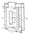
- a solid fuel furnace 10 intended for use as a pre-burner.
- the furnace 10 is of the grateless type and comprises a substantially elongate cylindrical combustion chamber 11 which is surrounded by a water jacket 12 having an inlet 13 and an outlet 14, to cool the walls of the chamber in well known manner.
- a hollow slag door 16 is provided to permit access to the interior of the furnace 10 for maintenance purposes, and at the other end 17, herein referred to as the rear end, there is an opening 18.
- the furnace 10 is intended to be connected at its rear end 17 to a boiler whereby hot gases produced by the furnace 10 may pass from the furnace 10 into the boiler through opening 18 and the heat they contain used to heat water of the boiler.
- a nozzle N is received in the opening 18 and extends through the water jacket 12 and is cooled thereby. The nozzle N facilitates the transfer of flame and hot gases produced during combustion in the furnace 10 to the boiler.
- the spent hot gases are passed from the boiler to a flue (not shown).
- valves 22 are controlled by electronically activated thrustors in response to a programme which permits the furnace to provide a predetermined output for a predeterimed time.
- the fuel falls under gravity to the bottom of the combustion chamber 11 wherein it forms a fire bed in which, when. the furnace is fired, combustion takes place.
- the bottom of the combustion chamber 11 is of V configuration and the sides 24, 25 of the V each have a plurality of apertures 26 in which tubes 27 comprising nozzles which extend generally downwards through the water jacket 12, are welded.
- the tubes 27 and thus water cooled and extend to air reservoirs 28a, 28b.
- the reservoir 28a has an inlet 29a which communicates with a duct D to which air is fed from a fan G.
- the duct D has a dividing wall W therein whereby the air from the fan G is divided into primary and secondary supplies, the primary supply passing to inlet 29a and thus into reservoir 28a, and the secondary supply is passed into a further duct 30.
- Dampers D' are provided in the duct D to regulate the primary and secondary supplies, and their dampers D' may be electronically or manually controlled.
- Air passes from reservoir 28a to a reservoir 28b by a duct E at the rear 17 of the furnace 10, and thus air from both the reservoirs 28a, 28b passes upwardly through the tubes 27 through the fire bed on the bottom of the combustion chamber 11 to provide a primary air supply, tc assist in combustion and to maintain the entire fire bed at a high temperature.
- the duct 30 extends from the duct D to a hollow 31 in the slag door 16 wherein the secondary air passes into the slag door 16.
- the slag door 16 has a plurality of apertures 32 therein whereby the secondary air supply passes into the combustion chamber above the level of the fire bed to further enhance combustion. It will be appreciated that the secondary air supply will be heated in the hollow door 16 thereby increasing the efficiency of the furnace.
- the water jacket 12 protects or reduces damage to the walls of the chamber 11 and to the other water cooled parts i.e. the nozzles 27 and N, and the channels 19, due to the great heat produced in the furnace.
- the high temperature is maintained throughout the fire bed and thus ashes, clinker and other noncombust- ibles, are melted, fused, or otherwise converted to slag.
- a water cooled clinker tray 41 is placed beneath the opening 40 to facilitate disposal of the slag.
- a conveyor or container may be placed beneath the opening 40.
- V-shaped bed having an included angle of approximately 100° provides optimum conditions so that the slag produced during combustion is removed at a rate such that unburnt fuel does not pass through opening 40 without reducing the efficiency of the furnace.
- the bottom of the combustion chamber 11 has been described as being in a V formation, if desired, any other configuration having a downwardly inclined part to direct the slag and other non-combustibles to an opening in a low part of the combustion chamber may be used.
- the side is preferably inclined at an angle between 30° and 50°, preferably about 400, to provide optimum conditions.
- the opening has been described as extending over substantially the entire length of the combustion chamber 11, if desired, the opening 31 may extend over part or parts of the length of the combustion chamber 11 only.
- the primary and/or secondary air supplies may be preheated by passing them over the top of the furnace 10. The secondary air may then pass into the hollow 31 of the slag door 16, and hence into the combustion chamber 11.
- a boiler may embody the invention.
- alternative means to the hopper 20 to feed the fuel to the fire bed may need to be employed, and the general configuration of the boiler adapted accordingly.
- At least the lower part of the furnace may be air cooled.
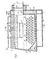
- the furnace 10' is similar to the furnace 10 of Figures 1 and 2 in many respects but is not entirely water cooled.
- the furnace 10' is again of the grateless type comprising an elongate, substantially cylindrical combustion chamber 11' having a central axis A'.
- a slag door 13' is provided to permit access to the interior of the furnace 10' for maintenance purposes.
- an exhaust opening 15' is provided at the rear end 14' of the combustion chamber 11' whereby hot gases may pass from the furnace 10' into the boiler and be used, for example to heat water.
- a nozzle 16' which is adapted to extend into a heating chamber of the boiler, is located in the opening 15' and is partially water cooled and partially cooled by tertiary air as described below. The spent gases are passed from the boiler to a flue (not shown).
- Two channels 17' are provided which extend from the exterior of the furnace into the combustion chamber 11'.
- Solid fuel may pass from a hopper 19' located above the furnace (only shown in Figure 2) via an inverted channel-shaped guide 18' through the channels 17' into the combustion chamber 11', the flow being regulated by gate valves (not shown) rotatable about pivots 18b which may be controlled manually via handles (not shown) or automatically by solenoids actuated by pressure or temperature thermostats of the furnace or boiler and/or an electronic control circuit which may be programmed to control the furnace to provide a predetermined output for a predetermined time.
- the solid fuel falls downwardly towards the bottom of the combustion chamber 11' and forms a bed of fuel which, when combusted, provides a fire bed.
- the channels 17' are each located either side of and equidistant from a vertical plane V' and just above a horizontal plane containing axis A'.
- the bottom of the combustion chamber 11' is of V configuration and the sides 40', 41' of the V each have a plurality of apertures 21' in which tubes 22' comprising nozzles which extend generally downwards to air reservoirs 42', 43', are welded.
- the reservoir 42' has an inlet 44' which, like inlet 29a of the Figure 1 and 2 construction, communicates with a duct D' to which air is fed from a fan G'.
- the duct D' has a dividing wall W' therein whereby the air from the fan G' is divided intc primary and secondary supplies, the primary supply passing to inlet 44' and thus into reservoir 42', and the secondary supply is passed into a further duct 25'.
- Air from the reservoir 42' passes to reservoir 43' by a duct E' at the rear 14' of the furnace 10', and thus air from both reservoirs 42', 43' passes upwardly through the nozzles 22' and through the fire bed on the bottom of the combustion chamber 11', said air comprising a primary air supply which assists in combustion and maintains the entire fire bed at a high temperature.
- the further duct 25' extends from the duct D' to spaces 31' in the roof of the furnace 10' wherein the secondary air passes downwardly through apertures 32' into the combustion chamber 11' above the level of the fire bed to further enhance combustion. It will be appreciated that the secondary air supply will be heated in the spaces 31' thereby increasing the efficiency of the furnace.
- a still further duct (not shown) directs a proportion of the primary air from the reservoirs 42, 43 to the nozzle 16' at the rear 14' of the furnace 10' to provide a tertiary air supply which is circulated around a hollow 16a' of the nozzle 16' whereby the tertiary air is heated and the nozzle 16' cooled.
- the tertiary air then passes through holes 26' in the nozzle 16' into the opening 15' to create a cyclone to ensure proper mixing of the hot gases and complete combustion of the fuel particles contained therein, as they pass from the furnace 10' into the boiler.
- the combustion chamber 11' is divided into two regions, an upper region 27a' and a lower region 27b'.
- Part of the upper region 27a' of the combustion chamber 11' i.e. a region above the channels 17', is lined with a layer of refractory material 29' of the type known as Durax 1600 concrete. Thus this part of the upper region 27a' of the combustion chamber is protected from heat damage.
- the lower region 27b' of the combustion chamber i.e. the region extending slightly above and extending below the channel 17', is provided with a water jacket 30' having an inlet (not shown) and an outlet (not shown) to cool the walls of the lower region 27b' of the chamber 11'.
- this furnace 10' is a hybrid between a water-cooled furnace wherein the entire combustion chamber is enveloped in a water jacket to cool the entire wall surface thereof, and a refractory-lined furnace wherein the entire internal surface of the combustion chamber is lined with refractory material.
- a grateless entirely water-cooled preburner furnace has the disadvantages that a proportion of the heat of the furnace which would otherwise be transferred to the boiler is lost to the water jacket, and, as it is usual to interconnect the water space of the boiler containing the water being heated and the water jacket of the furnace to increase the efficiency of the furnace and reduce heat loss, it is difficult to remove the preburner furnace from the boiler for maintenance purposes.
- Grateless preburner furnaces which are entirely lined with refractory have the disadvantages that clinker and slag adhere to the refractory, and fuel such as coal abrades the surface as it moves relative thereto thereby damaging the refractory. This is especially important in the present case as the slag and clinker are encouraged to move over the inclined parts 40', 41' to the opening 45'. Further, the nozzles which provide the primary air to the fire bed and the secondary air above the fire bed, become damaged by the heat produced by the furance.
- the hybrid furnace described combines the advantages of both types of known furnace and substantially overcomes the disadvantages of both types of furnace.
- a water cooled clinker tray 46' may be placed beneath the opening 45' to facilitate disposal of the slag. However, if desired, a conveyor or container may be placed beneath the opening 45'.
- the bottom of the combustion chamber 11' has been described as being in a V formation, if desired, any other configuration having a downwardly inclined part to direct the slag and other non-combustibles to an opening in a low part of the combustion chamber may be used.
- the opening 45' has been described as extending over substantially the entire length of the combustion chamber 11', if desired, the opening 45' may extend over part or parts of the length of the combustion chamber 11' only.
- the extent to which the combustion chamber is refractory lined has been described as comprising the region or part of the region between the channels 17' a greater or lesser region may be refractory lined, as desired.
- the means for supplying solid fuel to the combustion chambers 11 or 11' has been described as comprising a hopper 19 or 19' but it will be appreciated that any other means may be employed, although the means described provide the advantage that an even flow of fuel is provided to both sides of the furnace 10' along the entire length thereof.
- furnace 10, 10' has been described as being cylindrical but if desired, furnaces of another suitable shape may embody the invention. Further, although a pre-burner furnace has been described, a boiler may embody the invention.
- FIG. 5 there is shown a combination of a boiler 210 and an auxiliary solid-fuel fired furnace 211, herein referred to as the furnace.
- the boiler 210 comprises a combustion tube 212 having a closed end 213, the other end 214 thereof having an opening 215.
- the boiler 210 is designed for oil and/or gas firing and is of overall smaller dimensions than would be a solid fuel fired boiler of the same rated output. In the boiler 210 shown, a door which closed the opening 215 having an oil and/or gas burner mounted therein, has been removed.
- the boiler 210 is of elongate substantially cylindrical configuration, the combustion tube 212 being located within a water space 216 through which a pass of smoke tubes 217 extend, in the longitudinal direction thereof, the tubes 217 opening at each end into smoke boxes 218 and 219 and surrounding the combustion tube 212 in a circular configuration.
- the boiler 210 is of the two pass type, the flame and hot gases being projected into the combustion tube 212 by the oil and/or gas burner mounted in the door, reversing direction as they reach the closed end 213 and contacting the wall of the combustion tube 212 thereby providing a first heating pass, and entering the smoke box 218 from where they pass along the smoke tubes 217 which provide the second heating pass to the smoke box 219 to the flue 220, whilst heating the water in the water space 216.
- a combustion tube of an oil and/or gas fired boiler is generally physically smaller than the equivalent solid fuel fired boiler for a given output as the calorific value of oil or gas is greater than solid fuel, and thus it is not necessary to burn such a great quantity of oil or gas at once.
- an auxiliary furnace 211 which is of the grateless type and comprises a combustion chamber 225 into which solid fuel is fed from a hopper 226 via two channels 227, one either side of the combustion chamber 225, to ensure that fuel is fed to and burnt along the entire length of the chamber 225.
- the flow of fuel from the hopper 226 is regulated by gate valves 230 which are controlled manually by a handle 231 or automatically by solenoids activated by pressure or temperature thermostats of the furnace 211 and/or the boiler 210, provided in an electronic control circuit programmed to provide a predetermined boiler output, for a predetermined time.
- the fuel falls to the bottom of the chamber 225 where, when combusted, it forms a fire bed.
- Air is passed into the combustion chamber 225, in the same manner as described in Figures 1 to 4, from a duct to which air is fed from a fan F.
- the duct has a dividing wall therein whereby the air from the fan F is divided into primary and secondary supplies, the primary supply passing to any inlet and thus into a reservoir, and the secondary supply is passed into a further duct 250.
- Dampers (not shown) are provided in the duct to regulate the primary and secondary supplies.
- Air passes from the reservoir upwardly through tubes and thus into the fire bed on the bottom of the combustion chamber 225 which will have primary air, passed therethrough to assist in combustion and to maintain the entire fire bed at a high temperature.
- the duct 250 extends to a hollow 251 in the slag door 229 wherein the secondary air passes into the slag door 229 for heating.
- the slag door 229 has apertures 252 therein whereby the secondary air supply passes into the combustion chamber above the level of the fire bed to further enhance combustion. It will be appreciated that as the secondary air supply is heated in the hollow door the efficiency of the furnace is increased.
- the secondary air supply will provide the furnace with a negative flame characteristic whereas solid fuel fired furnaces normally have a positive flame characteristic.
- Slag, clinker and other non-combustibles may be removed from the furnace 211 via the slag door 229 at the forward end 228 of the combustion chamber 225.
- an extension nozzle 233 extending therefrom which, in use, is inserted into the combustion tube 212 of the boiler 210 to permit the flame and hot gases from the furnace 211 to pass into the boiler 210.
- Substantially the entire combustion chamber 225 is water cooled, the combustion chamber 225 being enveloped in a water jacket 234 having an inlet 235 and an outlet 236, the inlet and outlet being interconnected with the water space 216 by pipework to provide a single water circulating system of the boiler and the furnace to improve the efficiency of the boiler.
- the extension nozzle 233 is also water cooled, the water being connected with that of the jacket 234.
- the pipework is provided with quick release couplings to facilitate removal of the furnace 211 from the boiler 210 for maintenance purposes.
- the level of the floor 237 beneath the furnace has been built up so that the nozzle 233 of the furnace is at the correct height for insertion into the opening 215 of the combustion tube 212, and the furnace 211 is mounted on wheels 238 to further facilitate removal. This may not be necessary with all furnaces.
- extension mossle 233 is of substantially the same length as the combustion chamber 225, which is itself substantially half the length of the combustion tube.
- the extension nozzle 233 extends substantially halfway into the combustion tube 212. Flame and hot gases from the furnace 211 will pass through the nozzle 233 into the boiler 210 and pass to the closed end 213 of the tube 212, reverse direction and pass back over the water cooled nozzle 233 through space 239 between the external wall of the nozzle 233 and the internal wall of the tube 212, into the smoke box 218.
- the two pass boiler shown will be converted to a three pass boiler when solid fuel fired by the nozzle 233, the extra pass being provided by virtue of the fact of the inter- connection of the water cooling system of the furnace and the water space of the boiler, the extension nozzle 233 being cooled by water of the water cooling system of the furnace.
- a fan may be provided in addition to fan F between the combustion tube 212 of the boiler 210 and the flue, 20 to increase the draught induced.
- an oil and/or gas burner 240 may be mounted on the door 229 of the furnace 211 as shown in dotted lines, so that the boiler 210 can be conventionally oil or gas fired if desired, and/or to provide a quick start up of the furnace 211.
- the nozzle 233 has been described as extend ing half way into the combustion tube 212 of the boiler, if required the dimensions of the boiler and furnace may be different in which case the nozzle will extend into the tube 212 a different amount. As a minimum, the nozzle 233 will need to extend at least a distance equal to the thickness of the wall of the furnace 211, but the nozzle 233 may be of any length provided that there is space adjacent the closed end of the tube '212 in which the hot gases can change direction.
- the oil or gas boiler can be solid-fuel fired and operated at its rated output. It has been found that the furnace/boiler combination described has an output up to 20% higher than the rated output of the boiler 210 when conventionally oil or gas fired.
- the furnace of the furnace/boiler combination shown in Figure 5 may be suitably modified to embody the present invention, by providing an opening in the bottom of the combustion chamber 225 of the furnace.
- the boiler 310 comprises a combustion tube 312 having a closed end 313, the other end 314 thereof having an opening 315.
- the boiler 310 is designed for oil and/or gas firing and is of smaller overall smaller dimensions than would be a solid fuel fired boiler of the same rated output.
- the boiler 310 is also of elongate substantially cylindrical configuration, the combustion tube 312 being located within a water space 316 of the boiler through which a pass of smoke tubes 317 extend. in the longitudinal direction thereof, the tubes 317 opening at each end into smoke boxes 318 and 319.
- the smoke tubes 317 do not surround the tube 312 as do the tubes 217 of the boiler 210 of Figure 5, but are in an overhead arrangement.
- the water space 316 has inlet and outlet flow connectors (not shown).
- the auxiliary furnace 311 is of the grateless type and comprises a combustion chamber 325 into which solid fuel is fed from a hopper 326 via two channels 327, one either side of the combustion chamber 325 to ensure that fuel is fed to and burnt along the entire length of the chamber 325.
- the flow of fuel from the hopper 326 is regulated by gate valves 330 which are controlled manually by a handle 331 or automatically by solenoids activated by pressure or temperature thermostats of the furnace 311 and/or the boiler 310.
- the fuel falls to the bottom of the chamber 325 where, when combusted, it forms a fire bed.
- Air is passed upwardly into the combustion chamber 325 through tubes welded in apertures in the bottom of the chamber 325 from a duct to which air is fed from a fan 3G' and a secondary supply is passed into the combustion chamber 325 from a further duct (not shown) above the level of the fire bed.
- Slag, clinker and other non-combustibles may be removed from the furnace 311 via a slag door 329 at the forward end 328 of the combustion chamber 325.
- an extension nozzle 333 extending therefrom which, in use, is inserted into the combustion tube 312 of the boiler 310 to permit the flame and hot gases from the combustion chamber 325 of the furnace 311 to pass into the combustion tube 312 of the boiler 310.
- Substantially the entire combustion chamber 325 is water cooled, the combustion chamber 325 being enveloped in a water jacket having an inlet 335 and an outlet 336.
- the extension nozzle 333 is also water cooled, the water jacket 365 thereof having inlet 363 and outlet 364 flow connectors.
- the level of the nozzle 333 is arranged so that the nozzle 333 of the furnace 311 is at the correct height for insertion into the opening 315 of the combustion tube 312.
- the nozzle 333 is separable from the remainder of the furnace 311 unlike the nozzle 233 of the furnace 211 of Figure 5. This is facilitated because the water jacket of the furnace 111, and the water jacket 365 of the nozzle 333, are not interconnected. Further, the jackets are independent of of the water space 316 of the boiler 310 hence facilitating removal of the furnace 311 from the boiler for maintenance.
- the hot water from the jacket of the furnace 311, the jacket 365 of the nozzle 333, and the water space 316 of the boiler 310 are all fed in parallel to be used for heating or as desired.
- the extension nozzle 333 in this example is of slightly greater length than the combustion chamber 325, of the furnace 311.
- the extension nozzle 333 extends slightly more than halfway into the combustion tube 312. Flame and hot gases from the furnace 311 will pass through the water cooled nozzle 333 to provide a first heating pass into the boiler 310 and pass to the closed end 313 of the tube 312, thereby to provide a seond heating pass, reverse direction and pass back over the water cooled nozzle 333 through space 339 between the external wall of the nozzle 333 and the internal wall of the tube 312, into the smoke box 318 and hence through smoke tubes 317 to the flue 320 to provide a third heating pass.
- this two pass boiler will also be converted tc a three pass boiler when solid fuel fired by the furnace 311 by virtue of the nozzle 333, the extra pass being provided by virtue of the fact that hot water from the nozzle 333 and furnace is utilised along with hot water from the water space 316 of the boiler 310.
- a pump may be necessary to increase the water flow and hence cooling capability of the jacket 365.
- the nozzle 233, 333 may comprise a plurality of smoke tubes enveloped in a water jacket.
- the nozzle 233, 333 need not be cylindrical, but may be triangular, elliptical, hexagonal or other poly- gonial in section.
- the nozzle may be provided without a water jacket but be refractory lined.
- nozzle 233, 333 Different lengths may be used if desired but as a minimum, the nozzle 233, 333 will need to extend at least a distance equal to the thickness of the wall of the furnace 211, 311 so that the flame and hot gases can be transferred from the furnace 311 into the combustion chamber 312 of the boiler 310.
- the nozzle 233, 333 may be of any greater length provided that there is space adjacent the closed end of the tube 212, 312 in which the hot gases can change direction.
- an oil or gas fired boiler can be solid-fuel fired and operated at its rated output. It has been found that the furnace/boiler combinations described have an output up to 20% higher than the rated output of the boiler 210, 310 when conventionally oil or gas fired.
Priority Applications (1)
| Application Number | Priority Date | Filing Date | Title |
|---|---|---|---|
| AT81106198T ATE12822T1 (de) | 1980-08-19 | 1981-08-07 | Verbrennungsoefen. |
Applications Claiming Priority (6)
| Application Number | Priority Date | Filing Date | Title |
|---|---|---|---|
| GB8026927 | 1980-08-19 | ||
| GB8026928 | 1980-08-19 | ||
| GB8026926 | 1980-08-19 | ||
| GB8026928 | 1980-08-19 | ||
| GB8026927 | 1980-08-19 | ||
| GB8026926 | 1980-08-19 |
Publications (3)
| Publication Number | Publication Date |
|---|---|
| EP0046248A2 true EP0046248A2 (fr) | 1982-02-24 |
| EP0046248A3 EP0046248A3 (en) | 1982-09-08 |
| EP0046248B1 EP0046248B1 (fr) | 1985-04-17 |
Family
ID=27260995
Family Applications (2)
| Application Number | Title | Priority Date | Filing Date |
|---|---|---|---|
| EP81106199A Expired EP0046249B1 (fr) | 1980-08-19 | 1981-08-07 | Combinaison de four et de chaudière |
| EP81106198A Expired EP0046248B1 (fr) | 1980-08-19 | 1981-08-07 | Fours |
Family Applications Before (1)
| Application Number | Title | Priority Date | Filing Date |
|---|---|---|---|
| EP81106199A Expired EP0046249B1 (fr) | 1980-08-19 | 1981-08-07 | Combinaison de four et de chaudière |
Country Status (4)
| Country | Link |
|---|---|
| US (1) | US4470359A (fr) |
| EP (2) | EP0046249B1 (fr) |
| CA (2) | CA1162791A (fr) |
| DE (2) | DE3168311D1 (fr) |
Cited By (3)
| Publication number | Priority date | Publication date | Assignee | Title |
|---|---|---|---|---|
| US6332411B1 (en) | 1999-01-14 | 2001-12-25 | Olga Panteleimonovna Skrotskaya | Furnace |
| US8811823B2 (en) | 2000-06-18 | 2014-08-19 | Beamus, Ltd. | Dynamic optical devices |
| CN109973984A (zh) * | 2019-04-26 | 2019-07-05 | 平顶山市百阳丰机械制造有限公司 | 一种锅炉用的水冷式后烟箱 |
Families Citing this family (11)
| Publication number | Priority date | Publication date | Assignee | Title |
|---|---|---|---|---|
| SE436298B (sv) * | 1983-04-26 | 1984-11-26 | Kils El Ab | Anordning vid en vermepanna anordning vid en vermepanna |
| US4726301A (en) * | 1985-03-13 | 1988-02-23 | Ormeaux Farrell P Des | System for extracting contaminants and hydrocarbons from cuttings waste in oil well drilling |
| US4920925A (en) * | 1986-11-07 | 1990-05-01 | Donlee Technologies Inc. | Boiler with cyclonic combustion |
| DK46091D0 (da) * | 1991-03-15 | 1991-03-15 | Uffe Pedersen | Bioenergibraender med tilbehoer |
| US5730088A (en) * | 1995-12-22 | 1998-03-24 | Db Riley, Inc. | Heat recovery steam generator |
| US6032616A (en) * | 1998-02-13 | 2000-03-07 | Jones; Leslie J. | Rapid response hot water heater |
| CA2467550A1 (fr) * | 2004-05-18 | 2005-11-18 | Albert Penner | Chaudiere alimentee au charbon |
| US10012412B2 (en) * | 2009-09-16 | 2018-07-03 | Heat Solutions, Inc. | Fluid heater |
| DE102010018427B4 (de) * | 2010-04-27 | 2012-03-01 | Scherdel Innotec Forschungs- Und Entwicklungs-Gmbh | Festbrennstoffofen sowie Heizungsanlage und Brauchwasseraufheizanlage mit einem Festbrennstoffofen |
| US9945553B2 (en) | 2010-12-06 | 2018-04-17 | Russel Duane Van Wyk | Aqueous working fluid steam generation system |
| US9121602B2 (en) * | 2010-12-06 | 2015-09-01 | Russel Duane Van Wyk | Steam generator |
Citations (4)
| Publication number | Priority date | Publication date | Assignee | Title |
|---|---|---|---|---|
| BE460184A (fr) * | ||||
| GB641024A (en) * | 1945-04-27 | 1950-08-02 | David Herbert Dahlstrand | Improvements in or relating to furnaces and the like |
| FR56447E (fr) * | 1941-10-23 | 1952-09-24 | Cie Des Procedes Gohin Poulenc | Dispositif de chauffage par gazogène et son application aux fours à températures élevées |
| GB682302A (en) * | 1943-04-16 | 1952-11-05 | Michel Aloys Antoine Desire An | Improvements in or relating to a combined boiler and furnace |
Family Cites Families (16)
| Publication number | Priority date | Publication date | Assignee | Title |
|---|---|---|---|---|
| US33057A (en) * | 1861-08-13 | Improvement in locomotive fire-boxes | ||
| DE161095C (fr) * | ||||
| US576874A (en) * | 1897-02-09 | Q o o o o c | ||
| US757949A (en) * | 1903-12-03 | 1904-04-19 | Caloric King Furnace Company | Furnace. |
| US1082126A (en) * | 1911-03-11 | 1913-12-23 | Emil F Krell | Furnace-stoker. |
| DE613953C (de) * | 1928-11-02 | 1935-05-29 | Eugen Burg | Flammrohrkessel |
| US1972429A (en) * | 1930-05-07 | 1934-09-04 | Bernard F Shaughnessy | Incinerator |
| FR774847A (fr) * | 1933-06-23 | 1934-12-14 | Brûleur à charbon fin | |
| CH182328A (de) * | 1935-03-01 | 1936-02-15 | Mueller Albert | Automatischer Brenner für Kleinkohle. |
| US3171388A (en) * | 1956-10-10 | 1965-03-02 | Ygnis Sa | Heating apparatus |
| SE371004B (fr) * | 1967-02-16 | 1974-11-04 | Ctc Ab | |
| US3477411A (en) * | 1967-12-22 | 1969-11-11 | Aqua Chem Inc | Heat recovery boiler with bypass |
| CH493791A (de) * | 1968-01-30 | 1970-07-15 | Volkswagenwerk Ag | Müllverbrennungsanlage |
| US3785304A (en) * | 1972-03-13 | 1974-01-15 | K Stookey | Method and apparatus for the thermal reduction of rubber or plastic material |
| US3822651A (en) * | 1973-09-04 | 1974-07-09 | D Harris | Water cooled kiln for waste disposal |
| US4206723A (en) * | 1976-07-08 | 1980-06-10 | Interliz Anstalt | Double-fired heating boiler |
-
1981
- 1981-08-07 EP EP81106199A patent/EP0046249B1/fr not_active Expired
- 1981-08-07 DE DE8181106199T patent/DE3168311D1/de not_active Expired
- 1981-08-07 EP EP81106198A patent/EP0046248B1/fr not_active Expired
- 1981-08-07 DE DE8181106198T patent/DE3169986D1/de not_active Expired
- 1981-08-17 US US06/293,402 patent/US4470359A/en not_active Expired - Fee Related
- 1981-08-19 CA CA000384227A patent/CA1162791A/fr not_active Expired
- 1981-08-19 CA CA000384223A patent/CA1165649A/fr not_active Expired
Patent Citations (4)
| Publication number | Priority date | Publication date | Assignee | Title |
|---|---|---|---|---|
| BE460184A (fr) * | ||||
| FR56447E (fr) * | 1941-10-23 | 1952-09-24 | Cie Des Procedes Gohin Poulenc | Dispositif de chauffage par gazogène et son application aux fours à températures élevées |
| GB682302A (en) * | 1943-04-16 | 1952-11-05 | Michel Aloys Antoine Desire An | Improvements in or relating to a combined boiler and furnace |
| GB641024A (en) * | 1945-04-27 | 1950-08-02 | David Herbert Dahlstrand | Improvements in or relating to furnaces and the like |
Cited By (4)
| Publication number | Priority date | Publication date | Assignee | Title |
|---|---|---|---|---|
| US6332411B1 (en) | 1999-01-14 | 2001-12-25 | Olga Panteleimonovna Skrotskaya | Furnace |
| US8811823B2 (en) | 2000-06-18 | 2014-08-19 | Beamus, Ltd. | Dynamic optical devices |
| CN109973984A (zh) * | 2019-04-26 | 2019-07-05 | 平顶山市百阳丰机械制造有限公司 | 一种锅炉用的水冷式后烟箱 |
| CN109973984B (zh) * | 2019-04-26 | 2024-02-27 | 平顶山市百阳丰机械制造有限公司 | 一种锅炉用的水冷式后烟箱 |
Also Published As
| Publication number | Publication date |
|---|---|
| EP0046248B1 (fr) | 1985-04-17 |
| EP0046249A2 (fr) | 1982-02-24 |
| DE3168311D1 (en) | 1985-02-28 |
| EP0046248A3 (en) | 1982-09-08 |
| CA1165649A (fr) | 1984-04-17 |
| DE3169986D1 (en) | 1985-05-23 |
| EP0046249B1 (fr) | 1985-01-16 |
| CA1162791A (fr) | 1984-02-28 |
| EP0046249A3 (en) | 1982-09-15 |
| US4470359A (en) | 1984-09-11 |
Similar Documents
| Publication | Publication Date | Title |
|---|---|---|
| US4267801A (en) | Circulating fluidized bed boiler | |
| EP0005964B1 (fr) | Chaudière et moyens de combustion pour celle-ci | |
| US4559882A (en) | Biomass-fueled furnace | |
| EP0046248B1 (fr) | Fours | |
| US4296711A (en) | Heating boiler | |
| CN105889901A (zh) | 一种燃烧方捆秸秆的固定炉排锅炉 | |
| US4593629A (en) | Solid fuel stoker | |
| US4279205A (en) | Storage | |
| EP2884200B1 (fr) | Chaudière de chauffage central | |
| AU594181B2 (en) | Furnace | |
| JP5568394B2 (ja) | 焼却装置 | |
| US4444153A (en) | Grateless furnace for solid fuel | |
| CN205664359U (zh) | 一种燃烧方捆秸秆的固定炉排锅炉 | |
| SU1149105A1 (ru) | Топка кип щего сло | |
| US2320410A (en) | Combination retort and hearth for stokers | |
| GB2082301A (en) | Grateless Pre-Burner Furnace | |
| JP2681140B2 (ja) | 廃棄物の焼却・溶融処理装置及び焼却・溶融処理方法 | |
| GB2075175A (en) | Solid fuel burners | |
| EP0039073B1 (fr) | Brûleur à combustible solide | |
| GB2092294A (en) | Solid Fuel Burning Apparatus | |
| GB2082302A (en) | Grateless Furnace for Converting Liquid or Gas Fired Boiler | |
| PL237505B1 (pl) | Kocioł grzewczy ze zgazowaniem na węgiel i jego pochodne | |
| RU2166150C2 (ru) | Топка | |
| GB2082300A (en) | Grateless Pre-burner Furnace | |
| US1373479A (en) | Smoke and gas burning firebox |
Legal Events
| Date | Code | Title | Description |
|---|---|---|---|
| PUAI | Public reference made under article 153(3) epc to a published international application that has entered the european phase |
Free format text: ORIGINAL CODE: 0009012 |
|
| AK | Designated contracting states |
Designated state(s): AT BE CH DE FR IT LU NL SE |
|
| PUAL | Search report despatched |
Free format text: ORIGINAL CODE: 0009013 |
|
| AK | Designated contracting states |
Designated state(s): AT BE CH DE FR IT LU NL SE |
|
| 17P | Request for examination filed |
Effective date: 19830218 |
|
| GRAA | (expected) grant |
Free format text: ORIGINAL CODE: 0009210 |
|
| AK | Designated contracting states |
Designated state(s): AT BE CH DE FR IT LI LU NL SE |
|
| PG25 | Lapsed in a contracting state [announced via postgrant information from national office to epo] |
Ref country code: NL Effective date: 19850417 Ref country code: LI Effective date: 19850417 Ref country code: IT Free format text: LAPSE BECAUSE OF FAILURE TO SUBMIT A TRANSLATION OF THE DESCRIPTION OR TO PAY THE FEE WITHIN THE PRESCRIBED TIME-LIMIT;WARNING: LAPSES OF ITALIAN PATENTS WITH EFFECTIVE DATE BEFORE 2007 MAY HAVE OCCURRED AT ANY TIME BEFORE 2007. THE CORRECT EFFECTIVE DATE MAY BE DIFFERENT FROM THE ONE RECORDED. Effective date: 19850417 Ref country code: CH Effective date: 19850417 Ref country code: BE Effective date: 19850417 Ref country code: AT Effective date: 19850417 |
|
| REF | Corresponds to: |
Ref document number: 12822 Country of ref document: AT Date of ref document: 19850515 Kind code of ref document: T |
|
| PG25 | Lapsed in a contracting state [announced via postgrant information from national office to epo] |
Ref country code: SE Effective date: 19850430 |
|
| REF | Corresponds to: |
Ref document number: 3169986 Country of ref document: DE Date of ref document: 19850523 |
|
| ET | Fr: translation filed | ||
| REG | Reference to a national code |
Ref country code: CH Ref legal event code: PL |
|
| PG25 | Lapsed in a contracting state [announced via postgrant information from national office to epo] |
Ref country code: LU Free format text: LAPSE BECAUSE OF NON-PAYMENT OF DUE FEES Effective date: 19850831 |
|
| NLV1 | Nl: lapsed or annulled due to failure to fulfill the requirements of art. 29p and 29m of the patents act | ||
| PLBE | No opposition filed within time limit |
Free format text: ORIGINAL CODE: 0009261 |
|
| STAA | Information on the status of an ep patent application or granted ep patent |
Free format text: STATUS: NO OPPOSITION FILED WITHIN TIME LIMIT |
|
| 26N | No opposition filed | ||
| PG25 | Lapsed in a contracting state [announced via postgrant information from national office to epo] |
Ref country code: FR Free format text: LAPSE BECAUSE OF NON-PAYMENT OF DUE FEES Effective date: 19890428 |
|
| PG25 | Lapsed in a contracting state [announced via postgrant information from national office to epo] |
Ref country code: DE Effective date: 19890503 |
|
| REG | Reference to a national code |
Ref country code: FR Ref legal event code: ST |