EP0045582A1 - Etanchéification de l'appareil tourneur pour contact gaz-liquide - Google Patents
Etanchéification de l'appareil tourneur pour contact gaz-liquide Download PDFInfo
- Publication number
- EP0045582A1 EP0045582A1 EP81303225A EP81303225A EP0045582A1 EP 0045582 A1 EP0045582 A1 EP 0045582A1 EP 81303225 A EP81303225 A EP 81303225A EP 81303225 A EP81303225 A EP 81303225A EP 0045582 A1 EP0045582 A1 EP 0045582A1
- Authority
- EP
- European Patent Office
- Prior art keywords
- liquid
- gas
- seal
- channel
- barrier
- Prior art date
- Legal status (The legal status is an assumption and is not a legal conclusion. Google has not performed a legal analysis and makes no representation as to the accuracy of the status listed.)
- Granted
Links
Images
Classifications
-
- F—MECHANICAL ENGINEERING; LIGHTING; HEATING; WEAPONS; BLASTING
- F16—ENGINEERING ELEMENTS AND UNITS; GENERAL MEASURES FOR PRODUCING AND MAINTAINING EFFECTIVE FUNCTIONING OF MACHINES OR INSTALLATIONS; THERMAL INSULATION IN GENERAL
- F16J—PISTONS; CYLINDERS; SEALINGS
- F16J15/00—Sealings
- F16J15/16—Sealings between relatively-moving surfaces
- F16J15/40—Sealings between relatively-moving surfaces by means of fluid
- F16J15/42—Sealings between relatively-moving surfaces by means of fluid kept in sealing position by centrifugal force
-
- B—PERFORMING OPERATIONS; TRANSPORTING
- B01—PHYSICAL OR CHEMICAL PROCESSES OR APPARATUS IN GENERAL
- B01D—SEPARATION
- B01D47/00—Separating dispersed particles from gases, air or vapours by liquid as separating agent
- B01D47/16—Apparatus having rotary means, other than rotatable nozzles, for atomising the cleaning liquid
Definitions
- THIS INVENTION is concerned with rotary apparatus for contacting a liquid with a gas and is particularly concerned with gas-tight sealing devices formed between relatively rotatable parts of such apparatus.
- gas should be understood to include also vapours.
- rotary apparatus for effecting contact between a liquid and a gas
- One form of such apparatus comprises .a rotatable member adapted to rotate at such speeds that liquid flowing radially outwardly through the rotatable member is subjected to high accelerations.
- the gas flows counter- or co-currently through the rotatable member and gas-liquid contact takes place within the rotatable member at high rates of mass transfer.
- a sealing device whose components are relatively rotatable but which effectively prevents the passage of gas direct from inlet to outlet, thereby by-passing the rotatable member.
- a liquid channel leads from a point on said projecting barrier in the vicinity of the radially outermost point of said barrier.
- the liquid channel be located within the projecting gas barrier and it is also preferred that the channel, while leading from a point in the vicinity of the radially outermost point, does not in fact lead from the outermost point itself.
- the channel is preferably of small cross-sectional area in order to limit or prevent any leakage of gas past the seal via the channel.
- a control valve may be disposed in the liquid flow from the channel to further minimise passage of gas through the channel; for example, the valve may automatically open to permit passage of liquid and restrict passage of gas.
- the sealing liquid may be the same as the liquid which is being treated in the gas-liquid contacting apparatus, in which case the excess liquid from the liquid channel may be conducted to combine with the liquid being treated.
- the sealing liquid may be different from that being treated, for example the sealing liquid may be of lower volatility, in which case the excess liquid from the liquid channel may be recirculated to the seal, either directly or via an external storage arrangement.
- the liquid contained in the seal will be lost from the liquid chamber in various ways, including evaporation arising from frictional heating of the liquid by virtue of viscous drag on rotation of the liquid relative to the gas barrier.
- Fresh liquid is therefore. added during operation.
- Such fresh liquid may be added via a liquid feed passage located adjacent to the liquid chamber.
- the passage may be in the form of a second liquid channel located within the projecting gas barrier which forms a part of the gas-tight seal of the present invention.
- the two parts between which a seal is formed according to the present invention have been described as .”relatively rotatable".
- the first such part upon or within which the liquid chamber is located is necessarily rotatable, so that liquid is retained within the chamber during rotation.
- the second such part may itself be rotatable or may be stationary.
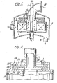
- the gas-liquid contacting apparatus of Figure 1 comprises a rotary member 1 mounted upon a shaft 2 by means of which it is rotated within a casing 3.
- the rotary member 1 carriers a permeable packing 4 distributed as an annulus about the axis of rotation of the member 1.
- Liquid to be treated by means of the apparatus is introduced via a liquid feed pipe 5 and is then sprayed through orifices in the lower end of pipe 5 on to the inner surface of the packing 4.
- Rotation of the member 1 subjects the liquid to high acceleration in a radial direction and the liquid permeates rapidly through the packing 4, encountering a counter-current flow of gas within the packing before being expelled from the outer surface of the latter and subsequently removed from the casing 3 via a liquid discharge pipe 6.
- the gas to be treated enters the apparatus via a gas feed pipe 7, passes under pressure radially inwardly through the packing 4 and is subsequently discharged through gas discharge pipe 8..
- liquid seal (indicated generally at 9) is to prevent gas passing direct from feed pipe 7 to discharge pipe 8, thus by-passing the packing 4 and emerging from the apparatus untreated.
- the conventional form of seal 9 illustrated consists of an annular liquid chamber 10 mounted rigidly upon the upper surface of the rotary member 1 to rotate therewith and a gas barrier 11 in the form of a disc projecting from the lower end of discharge pipe 8 into the chamber 10.
- the chamber 10 is filled with a seal liquid (which may be the same-as the liquid to be treated) by means of a seal liquid feed pipe 12.
- the seal liquid is retained in chamber 10 by the centrifugal action induced by rotation of the rotary member 1 and passage of gas through the seal is thereby prevented, provided that the liquid head in the chamber is sufficient to counter-balance the gas pressure difference across packing 4.
- a liquid chamber 20 is mounted directly upon a rotary member 21 containing permeable packing 22 and is defined by the upper wall 23 of the rotary member 21, and by a cylindrical outer chamber wall 24 and an annular upper chamber wall 25.
- seal liquid feed pipe 29 by means of which seal liquid is introduced into chamber 20, both initially and also as necessary to replace liquid lost from chamber 20 during operation of the apparatus. While the particular embodiment illustrated has a single liquid channel 28 and a single seal liquid feed pipe 29, it is equally possible to provide two, three. or more liquid channels and/or liquid feed pipes. Such multiple channels and/or pipes may be uniformly distributed about the circumference of the disc-shaped barrier 26.
- the chamber 20 is filled with seal liquid and rotary member 21 is rotated.
- the pipe 27 and barrier 26 remain stationary.
- centrifugal action presses'the seal liquid radially outwardly within chamber 20 and the liquid becomes so disposed that the difference between the radial positions of the liquid surface above and below the barrier 26 (the distance marked 'A' in Figure 2) represents the liquid head necessary to counter-balance the difference in gas pressure across the packing 22. Since seal liquid is free to overflow through liquid channel 28, the datum line from which the liquid head extends will always lie at the entrance to channel 28.
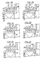
- the conventional seal illustrated in Figures 3a, 3c and 3e comprises a liquid chamber 30 defined by the upper wall 31 of a rotary member 32 and by a cylindrical outer chamber wall 33 and an annular upper chamber wall 34.
- a stationary disc-shaped barrier 35 projects from the bottom of gas discharge pipe 36 into the liquid chamber 30.
- the seal according to the present invention illustrated_in Figures 3b, 3d and 3f differs from the conventional seal in'two respects.
- the provision of a liquid channel 37 makes it possible to employ a smaller liquid chamber and therefore the annular upper chamber wall 34a is radially much narrower than the corresponding wall 34 of the conventional seal.
- Figures 3a and 3b show the seals in a condition in which the gas pressure difference across the seal is zero.
- the radial positions of the liquid surface are the same above and below the gas barrier 35.
- this state is achieved with much less seal liquid in the case of the seal according to the present invention.
- a consequence of this difference is that the barrier 35 is much less deeply immersed.in seal liquid and viscous drag in this pressure condition is greatly reduced.
- Figures 3c and 3d illustrate a similar comparison with the gas pressure difference across the seal at an intermediate value. Again the volume of seal liquid is substantially less in the case of the seal according to the present invention.
- Figures 3e and 3f illustrate a similar comparison at maximum gas pressure difference.
- the volume of liquid in the two devices is substantially the same but the condition has been achieved, in the case of the present invention, without passing through an intermediate condition which required the upper chamber wall to be radially wide and massive.
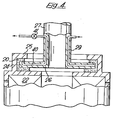
- FIG 4 A modified form of the seal according to Figure 2 is shown in Figure 4.
- the liquid channel 28 is replaced by a modified liquid channel 40 which, instead of returning liquid to the treatment zone, leads via an extension in the wall of gas discharge pipe 27 away from the treatment zone.
- a control valve 41 is located downstream of the liquid channel and is designed to open to permit passage of liquid but to restrict passage of gas. Liquid discharged via liquid channel 40 and control valve 41 may be recycled as necessary via seal liquid feed pipe 29 to maintain the desired level of liquid in the chamber 20.
- seal design shown in Figure 4 enables the use of a seal liquid different from the liquid to be treated in the gas-liquid contacting apparatus.
- a seal liquid may be chosen which has properties, for example low volatility, especially appropriate to the sealing function, without regard to its compatibility with the liquid undergoing treatment.
Priority Applications (1)
| Application Number | Priority Date | Filing Date | Title |
|---|---|---|---|
| AT81303225T ATE10228T1 (de) | 1980-08-01 | 1981-07-14 | Abdichtung des drehapparates fuer gasflssssigkeitsbersshrung. |
Applications Claiming Priority (2)
| Application Number | Priority Date | Filing Date | Title |
|---|---|---|---|
| GB8025242 | 1980-08-01 | ||
| GB8025242 | 1980-08-01 |
Publications (2)
| Publication Number | Publication Date |
|---|---|
| EP0045582A1 true EP0045582A1 (fr) | 1982-02-10 |
| EP0045582B1 EP0045582B1 (fr) | 1984-11-07 |
Family
ID=10515201
Family Applications (1)
| Application Number | Title | Priority Date | Filing Date |
|---|---|---|---|
| EP81303225A Expired EP0045582B1 (fr) | 1980-08-01 | 1981-07-14 | Etanchéification de l'appareil tourneur pour contact gaz-liquide |
Country Status (8)
| Country | Link |
|---|---|
| US (1) | US4397795A (fr) |
| EP (1) | EP0045582B1 (fr) |
| JP (1) | JPS5757963A (fr) |
| AT (1) | ATE10228T1 (fr) |
| AU (1) | AU544363B2 (fr) |
| CA (1) | CA1155884A (fr) |
| DE (1) | DE3167067D1 (fr) |
| ZA (1) | ZA815154B (fr) |
Cited By (6)
| Publication number | Priority date | Publication date | Assignee | Title |
|---|---|---|---|---|
| FR2548752A1 (fr) * | 1983-07-08 | 1985-01-11 | Rolls Royce | Joint liquide pour gaz avec balayage de fluide |
| FR2591704A1 (fr) * | 1985-12-18 | 1987-06-19 | Legoy Sa | Garniture d'etancheite autostable a depression pour machines tournantes et en particulier pour pompes |
| FR2628767A1 (fr) * | 1988-03-21 | 1989-09-22 | Sunds Defibrator Jylha Oy | Joint pour l'etancheite de passage d'un arbre rotatif |
| EP0561014A1 (fr) * | 1992-03-16 | 1993-09-22 | BECKER VERFAHRENSTECHNIK, DIPL. ING. ERNST BECKER GmbH & CO KG | Joint dynamique d'étanchéité sans contact |
| CN102641718A (zh) * | 2012-04-28 | 2012-08-22 | 浙江工业大学 | 一种用于超重力旋转床的盘形离心液环动密封装置 |
| CN109854751A (zh) * | 2019-03-19 | 2019-06-07 | 江苏赛德力制药机械制造有限公司 | 卧式沉降离心机用密封隔爆装置 |
Families Citing this family (6)
| Publication number | Priority date | Publication date | Assignee | Title |
|---|---|---|---|---|
| US4664732A (en) * | 1981-04-27 | 1987-05-12 | Raychem Corp. | Methods and apparatus for optical fiber systems |
| EP0080311B1 (fr) * | 1981-11-24 | 1986-01-15 | Imperial Chemical Industries Plc | Appareil de contact |
| ATE68398T1 (de) * | 1987-09-02 | 1991-11-15 | Babcock Bsh Ag | Mischer zum herstellen von moertel aus feinkoernigen bindemitteln, insbesondere gips. |
| GB0623705D0 (en) * | 2006-11-28 | 2007-01-10 | Cummins Turbo Tech Ltd | Hydraulic for a turbocharger |
| CN108071806B (zh) * | 2016-11-15 | 2019-12-10 | 超重力有限公司 | 旋转轴液封装置 |
| CN108953581A (zh) * | 2018-10-08 | 2018-12-07 | 广州达意隆包装机械股份有限公司 | 一种星轮座 |
Citations (6)
| Publication number | Priority date | Publication date | Assignee | Title |
|---|---|---|---|---|
| DE155953C (fr) * | ||||
| GB757149A (en) * | 1953-06-29 | 1956-09-12 | Claes Wilhelm Pilo | Apparatus for the performance of an exchange of heat and/or soluble substances between two flowing media of different specific gravity |
| GB859097A (en) * | 1957-05-23 | 1961-01-18 | Claes Wilhelm Pilo | Apparatus for effecting an exchange of heat and/or material between a gas or vapour and a liquid |
| GB1284596A (en) * | 1969-12-20 | 1972-08-09 | Rolls Royce | Improvements in or relating to hydraulic seals |
| DE2400075A1 (de) * | 1973-01-01 | 1974-07-11 | Claes Wilhelm Pilo | Gaswaescher |
| US3910585A (en) * | 1972-11-07 | 1975-10-07 | Cnen | Hydraulic multicellular sealing device for centrifugal pumps |
Family Cites Families (9)
| Publication number | Priority date | Publication date | Assignee | Title |
|---|---|---|---|---|
| US822802A (en) * | 1905-11-24 | 1906-06-05 | Wilkinson Turbine Company | Shaft-packing. |
| US2699225A (en) * | 1951-10-06 | 1955-01-11 | Rosenblad Corp | Method for the cooling of gas containing naphthalene |
| US2941872A (en) * | 1959-06-09 | 1960-06-21 | Pilo | Apparatus for intimate contacting of two fluid media having different specific weight |
| GB1241412A (en) * | 1967-06-22 | 1971-08-04 | Svenska Rotor Maskiner Ab | Improvements in apparatus for causing contact between two fluids of different densities |
| US3596885A (en) * | 1968-07-24 | 1971-08-03 | Arthur F Stone | Method and apparatus for scrubbing gas |
| NL166858C (nl) * | 1969-05-24 | 1981-10-15 | Petersen Hugo Verfahrenstech | Inrichting voor het nat reinigen van een met stofdeel- tjes verontreinigd gas. |
| US3744773A (en) * | 1971-02-10 | 1973-07-10 | Borg Warner | A furnace plenum or duct type humidifier |
| US3765688A (en) * | 1971-07-19 | 1973-10-16 | Avco Corp | High speed shaft centrifuge fluid seal |
| EP0002568B1 (fr) * | 1977-12-01 | 1984-06-20 | Imperial Chemical Industries Plc | Dispositif pour l'échange de masse et son utilisation |
-
1981
- 1981-07-14 EP EP81303225A patent/EP0045582B1/fr not_active Expired
- 1981-07-14 DE DE8181303225T patent/DE3167067D1/de not_active Expired
- 1981-07-14 AT AT81303225T patent/ATE10228T1/de not_active IP Right Cessation
- 1981-07-20 US US06/284,943 patent/US4397795A/en not_active Expired - Fee Related
- 1981-07-23 AU AU73364/81A patent/AU544363B2/en not_active Ceased
- 1981-07-27 ZA ZA815154A patent/ZA815154B/xx unknown
- 1981-07-31 CA CA000383034A patent/CA1155884A/fr not_active Expired
- 1981-07-31 JP JP56120626A patent/JPS5757963A/ja active Granted
Patent Citations (6)
| Publication number | Priority date | Publication date | Assignee | Title |
|---|---|---|---|---|
| DE155953C (fr) * | ||||
| GB757149A (en) * | 1953-06-29 | 1956-09-12 | Claes Wilhelm Pilo | Apparatus for the performance of an exchange of heat and/or soluble substances between two flowing media of different specific gravity |
| GB859097A (en) * | 1957-05-23 | 1961-01-18 | Claes Wilhelm Pilo | Apparatus for effecting an exchange of heat and/or material between a gas or vapour and a liquid |
| GB1284596A (en) * | 1969-12-20 | 1972-08-09 | Rolls Royce | Improvements in or relating to hydraulic seals |
| US3910585A (en) * | 1972-11-07 | 1975-10-07 | Cnen | Hydraulic multicellular sealing device for centrifugal pumps |
| DE2400075A1 (de) * | 1973-01-01 | 1974-07-11 | Claes Wilhelm Pilo | Gaswaescher |
Cited By (8)
| Publication number | Priority date | Publication date | Assignee | Title |
|---|---|---|---|---|
| FR2548752A1 (fr) * | 1983-07-08 | 1985-01-11 | Rolls Royce | Joint liquide pour gaz avec balayage de fluide |
| DE3424969A1 (de) * | 1983-07-08 | 1985-01-17 | Rolls-Royce Ltd., London | Fluessigkeitsringdichtung |
| FR2591704A1 (fr) * | 1985-12-18 | 1987-06-19 | Legoy Sa | Garniture d'etancheite autostable a depression pour machines tournantes et en particulier pour pompes |
| FR2628767A1 (fr) * | 1988-03-21 | 1989-09-22 | Sunds Defibrator Jylha Oy | Joint pour l'etancheite de passage d'un arbre rotatif |
| EP0561014A1 (fr) * | 1992-03-16 | 1993-09-22 | BECKER VERFAHRENSTECHNIK, DIPL. ING. ERNST BECKER GmbH & CO KG | Joint dynamique d'étanchéité sans contact |
| CN102641718A (zh) * | 2012-04-28 | 2012-08-22 | 浙江工业大学 | 一种用于超重力旋转床的盘形离心液环动密封装置 |
| CN109854751A (zh) * | 2019-03-19 | 2019-06-07 | 江苏赛德力制药机械制造有限公司 | 卧式沉降离心机用密封隔爆装置 |
| CN109854751B (zh) * | 2019-03-19 | 2024-01-26 | 江苏赛德力制药机械制造有限公司 | 卧式沉降离心机用密封隔爆装置 |
Also Published As
| Publication number | Publication date |
|---|---|
| ATE10228T1 (de) | 1984-11-15 |
| ZA815154B (en) | 1982-10-27 |
| JPS645184B2 (fr) | 1989-01-30 |
| EP0045582B1 (fr) | 1984-11-07 |
| DE3167067D1 (en) | 1984-12-13 |
| AU7336481A (en) | 1982-02-04 |
| AU544363B2 (en) | 1985-05-23 |
| US4397795A (en) | 1983-08-09 |
| JPS5757963A (en) | 1982-04-07 |
| CA1155884A (fr) | 1983-10-25 |
Similar Documents
| Publication | Publication Date | Title |
|---|---|---|
| US4397795A (en) | Seal for rotary apparatus for gas-liquid contacting | |
| US4523764A (en) | Fluid-sealed shaft seal with bores for supplying and discharging fluid | |
| CA1193540A (fr) | Dispositif centrifuge de contact de gaz et liquide | |
| US4382045A (en) | Centrifugal gas-liquid contact apparatus | |
| US2546381A (en) | Apparatus for concentrating liquids | |
| US3486743A (en) | Multistage vapor-liquid contactor | |
| KR920006647B1 (ko) | 원심 분리기 | |
| JPS60209275A (ja) | 遠心分離装置 | |
| NO137374B (no) | Sentrifugalseparator. | |
| US2178547A (en) | Centrifugal separator | |
| US4272011A (en) | Centrifugal counterflow type contactor | |
| RU1831560C (ru) | Установка дл уменьшени давлени в жидкой смеси из сложных углеводородов от заданной величины | |
| KR920010883B1 (ko) | 원심분리기의 유체 수위 유지 시스템 | |
| GB1589804A (en) | Labyrinth seals | |
| US3637134A (en) | Apparatus for indicating the sludge level in centrifuges | |
| SE503458C2 (sv) | Centrifugtrumma | |
| US2153640A (en) | Seal for centrifugal fluid treating apparatus | |
| US5368313A (en) | Bushing for trapped bushing seal | |
| US4140158A (en) | Pipeless filling unit for counterpressure bottling machines | |
| US1970552A (en) | Apparatus for centrifugal separation | |
| US3231185A (en) | Centrifugal countercurrent contact systems | |
| WO1985000022A1 (fr) | Montage de sortie pour un separateur centrifuge | |
| US3231184A (en) | Liquid contact process and apparatus | |
| US2912172A (en) | Sterilizable centrifugal atomizer for spray driers | |
| US2028949A (en) | Filter |
Legal Events
| Date | Code | Title | Description |
|---|---|---|---|
| PUAI | Public reference made under article 153(3) epc to a published international application that has entered the european phase |
Free format text: ORIGINAL CODE: 0009012 |
|
| AK | Designated contracting states |
Designated state(s): AT BE CH DE FR GB IT LI NL SE |
|
| 17P | Request for examination filed |
Effective date: 19820706 |
|
| ITF | It: translation for a ep patent filed |
Owner name: ING. C. GREGORJ S.P.A. |
|
| GRAA | (expected) grant |
Free format text: ORIGINAL CODE: 0009210 |
|
| AK | Designated contracting states |
Designated state(s): AT BE CH DE FR GB IT LI NL SE |
|
| REF | Corresponds to: |
Ref document number: 10228 Country of ref document: AT Date of ref document: 19841115 Kind code of ref document: T |
|
| REF | Corresponds to: |
Ref document number: 3167067 Country of ref document: DE Date of ref document: 19841213 |
|
| ET | Fr: translation filed | ||
| PLBE | No opposition filed within time limit |
Free format text: ORIGINAL CODE: 0009261 |
|
| STAA | Information on the status of an ep patent application or granted ep patent |
Free format text: STATUS: NO OPPOSITION FILED WITHIN TIME LIMIT |
|
| 26N | No opposition filed | ||
| PGFP | Annual fee paid to national office [announced via postgrant information from national office to epo] |
Ref country code: AT Payment date: 19920611 Year of fee payment: 12 |
|
| PGFP | Annual fee paid to national office [announced via postgrant information from national office to epo] |
Ref country code: SE Payment date: 19920617 Year of fee payment: 12 Ref country code: DE Payment date: 19920617 Year of fee payment: 12 Ref country code: CH Payment date: 19920617 Year of fee payment: 12 |
|
| PGFP | Annual fee paid to national office [announced via postgrant information from national office to epo] |
Ref country code: BE Payment date: 19920623 Year of fee payment: 12 |
|
| PGFP | Annual fee paid to national office [announced via postgrant information from national office to epo] |
Ref country code: GB Payment date: 19920626 Year of fee payment: 12 |
|
| PGFP | Annual fee paid to national office [announced via postgrant information from national office to epo] |
Ref country code: FR Payment date: 19920728 Year of fee payment: 12 |
|
| ITTA | It: last paid annual fee | ||
| PGFP | Annual fee paid to national office [announced via postgrant information from national office to epo] |
Ref country code: NL Payment date: 19920731 Year of fee payment: 12 |
|
| PG25 | Lapsed in a contracting state [announced via postgrant information from national office to epo] |
Ref country code: GB Effective date: 19930714 Ref country code: AT Effective date: 19930714 |
|
| PG25 | Lapsed in a contracting state [announced via postgrant information from national office to epo] |
Ref country code: SE Effective date: 19930715 |
|
| PG25 | Lapsed in a contracting state [announced via postgrant information from national office to epo] |
Ref country code: LI Effective date: 19930731 Ref country code: CH Effective date: 19930731 Ref country code: BE Effective date: 19930731 |
|
| BERE | Be: lapsed |
Owner name: IMPERIAL CHEMICAL INDUSTRIES P.L.C. Effective date: 19930731 |
|
| PG25 | Lapsed in a contracting state [announced via postgrant information from national office to epo] |
Ref country code: NL Effective date: 19940201 |
|
| GBPC | Gb: european patent ceased through non-payment of renewal fee |
Effective date: 19930714 |
|
| NLV4 | Nl: lapsed or anulled due to non-payment of the annual fee | ||
| PG25 | Lapsed in a contracting state [announced via postgrant information from national office to epo] |
Ref country code: FR Effective date: 19940331 |
|
| REG | Reference to a national code |
Ref country code: CH Ref legal event code: PL |
|
| PG25 | Lapsed in a contracting state [announced via postgrant information from national office to epo] |
Ref country code: DE Effective date: 19940401 |
|
| REG | Reference to a national code |
Ref country code: FR Ref legal event code: ST |
|
| EUG | Se: european patent has lapsed |
Ref document number: 81303225.7 Effective date: 19940210 |