EP0045337A1 - Connecting a subtle material to a structure - Google Patents
Connecting a subtle material to a structure Download PDFInfo
- Publication number
- EP0045337A1 EP0045337A1 EP19800401153 EP80401153A EP0045337A1 EP 0045337 A1 EP0045337 A1 EP 0045337A1 EP 19800401153 EP19800401153 EP 19800401153 EP 80401153 A EP80401153 A EP 80401153A EP 0045337 A1 EP0045337 A1 EP 0045337A1
- Authority
- EP
- European Patent Office
- Prior art keywords
- rigid
- flexible material
- plane
- cell
- attachment
- Prior art date
- Legal status (The legal status is an assumption and is not a legal conclusion. Google has not performed a legal analysis and makes no representation as to the accuracy of the status listed.)
- Ceased
Links
Images
Classifications
-
- A—HUMAN NECESSITIES
- A45—HAND OR TRAVELLING ARTICLES
- A45F—TRAVELLING OR CAMP EQUIPMENT: SACKS OR PACKS CARRIED ON THE BODY
- A45F5/00—Holders or carriers for hand articles; Holders or carriers for use while travelling or camping
-
- B—PERFORMING OPERATIONS; TRANSPORTING
- B65—CONVEYING; PACKING; STORING; HANDLING THIN OR FILAMENTARY MATERIAL
- B65H—HANDLING THIN OR FILAMENTARY MATERIAL, e.g. SHEETS, WEBS, CABLES
- B65H75/00—Storing webs, tapes, or filamentary material, e.g. on reels
- B65H75/02—Cores, formers, supports, or holders for coiled, wound, or folded material, e.g. reels, spindles, bobbins, cop tubes, cans, mandrels or chucks
- B65H75/18—Constructional details
- B65H75/28—Arrangements for positively securing ends of material
Definitions
- the present invention relates to a method for hanging a flexible material, shaped into wire, tape or sheet, on a rigid part, and concerns all the fields of activity where such a problem must be resolved, nar example: handling (hanging of slings), packaging (fixing of ribbons or rolls on reel, as for typewriters), furniture (fixing of panels, curtains, canvases of hamecs, etc.), leather goods, saddlery and tools (kits and various cases that can be worn attached to the belt), sports equipment (quiver, sails, hanging of tensioners, attachment of ropes on capstan drum); door interlocker, etc.
- handling hanging of slings
- packaging fixing of ribbons or rolls on reel, as for typewriters
- furniture fixing of panels, curtains, canvases of hamecs, etc.
- leather goods leather goods
- saddlery and tools kits and various cases that can be worn attached to the belt
- sports equipment quiver, sails, hanging of tensioners, attachment of ropes on capstan drum
- door interlocker etc
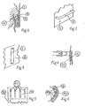
- the invention is characterized in that, at each of its attachment points, the material (1), flexible in the direction of FIG. 1, is made rigid over a certain portion (2) of its dimension along the plane of the figure, and that this rigid part (2) is introduced into the cell (3) of a rigid part (4).
- the length, in the plane of the rigid part (2) is less than the depth of the cell (3) but much greater than its width, so that the traction exerted upwards on the upper part (1) of the material flexible has the effect of applying this material on the right edge of the cell (3), and this traction has the effect of bracing the rigid part (2) against the left wall of the cell (3).
- the more the equilibrium position of this rigid part (2) is close to the axis of the cell (3) according to the plane of the figure, the less the bending forces which it must balance by its rigidity.
- the invention is characterized by the mere fact of making the flexible material rigid in one of its parts such as (2) defining a point of attachment, and not by the means used to obtain this result.
- Figure 1 shows a section of a point of dislocation but the dimension of the socket and the parts in contact is not specified in the direction porpendiculaipe in the plane of the figure. From this point of view, it should be specified that, if the flexible material (1) is in the form of a sheet or, at least, of a fairly wide gold ribbon or strap, that is to say -to say that its dimension perpendicular to the plane of the figure is at least of the order of ten times its thickness represented in the plen of the figure, its rigidity in a plane perpendicular to the plane of the figure is sufficient for that the cell (3) does not need side walls above and below the plane of the figure.
- the flexible material (1) is in the form of wire or cable, that is to say that its dimension perpendicular to the plane of the figure is approximately equal to its thickness measured in the plane of Figure 1, it is absolutely necessary that the cell (3) has side walls above and below the plane of Figure 1 to guide and maintain the rigid part (2) in the plane of the figure.
- FIG. 1 shows a piece (4) attached to a piece (1) of flexible material; but by symmetry about a horizontal axis contained in the plane of the figure, the alveolus (3) would come on top of the part (4) and the part (1) of the flexible material would hang, hooked to the part ( 4). More generally, whatever its orientation, FIG. 1 represents the attachment of the flexible material 1 on which a traction is exerted tending to move it away from the part (4) in a direction parallel to the axis of the cell (3) and in a direction such that this traction applies the flexible material to the edge of the cell (3) and causes the bracing of the rigid part (2) against the edge of the opposite cell (3) to the previous one.
- FIG. 3 which represents a portion of tube (7) fixed by gluing or welding to a part (8) is the counterpart of FIG. 2 in the case, no longer of a strap or of a ribbon, but of a wire or cable.
- the material (8) is sufficiently resistant and if it can be pierced with a through hole sufficiently close to its outer surface, the attached tube (7) can very well be replaced by such a hole.
- FIG. 4 represents a device for attaching to a belt a piece of flexible material (9), for example a case or quiver, terminated by a part (10) made rigid in the plane of the figure.
- the rigidity in the plane of Figure 4 is mandatory for the attachment, but the flexibility of the part (10) around an axis contained in the plane of Figure 4 may be necessary to follow a curved wall in the same meaning.
- the part (10) (fig. 4, fig. 5 and fig. 6) is made rigid in a single plane by means of mutually parallel reinforcements such as (11), which allow the part (10 ) around a vertical axis of Figure 5, but not around a horizontal axis of this same figure.
- Figure 6 shows a section seen from above of the attachment made by means of parts such as (9), (10) and (11) on a bar such as (5), in the case where the wall (6) of Figure 2 is convex.
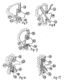
- Figures 7 and 8 show another embodiment of a hooking of a flexible material (13), (14) of which a part (15) has been made rigid in the plane of the figure, on a rigid part (12), (16).
- the traction exerted on the part (13) of the flexible material is transmitted by the rigidity of the part (15) which causes the jamming of the free strand (14) in the acute dihedron of edge perpendicular to the plane of the figure. , which is formed by the part (16) and the lower lip (12) of the attachment socket.
- Figure 7 shows this latching in the locked position and Figure 8, the same during engagement or disengagement, the part (13) not being subjected to traction.
- Figure 9 is a variant of the figure? where, the rigid part (15) not being able to slide along the flexible material under the action of the traction exerted at (13), the pinching exerted between (16) and (12) of FIG. 7 does not is no longer necessary and a simple bracing of the end of the rigid part (15) against the bottom of the cell is sufficient.
- the rigid portion (15) could be produced by means of a sheath of rigid material in which the flexible material can slide.
- the rigid portion (15) would for example be produced by bonding rigid plates to the flexible material, or else by threading rigid plates into gussets formed by the flexible material.
- FIGS. 7, 8, 9, 10 and 11 has been shown, delimited by a dashed line, the zone of clearance necessary for detachment, which is produced by extraction of the rigid part of the flexible material from the catching alveolus .
- the tension exerted on the part (13) must be released in the case of FIGS. 7, 8 and 9, and the extraction of the rigid part (15) from the cell is obtained by pulling on the part (14) of the flexible material.
- the lower part of the attachment socket consists of a rigid part (18) with a cross-section in the plane of the figure, the dimension of which is perpendicular to the plane of the figure is the same as that of the parts (13), (14), (15) and (17), and which is movable around an axis (19) integral with the support (17).
- the axis (19) perpendicular to the plane of the figure is located as close as possible to the rectilinear wall of the part (17), but at a distance at least equal to the sum of the thickness of the rigid part (15) and free strand (14).
- the traction on the part (13) presses the part (15) and the strand loop (14) on the horizontal wing of the bracket (18) causing the part (15) and the strand (14) to be pinched between the vertical wing of the bracket (18) and the part (17).
- a moderate traction exerted on (14) allows the rotation to the right of the square (18) around its axis (19) and the release of the rigid part (15), even in the presence of a traction on the part ( 13).
- FIG. 11 responds to the same explanations of operation as in FIG. 10, with the exception of the replacement of the rigid part (15) of the flexible material with a piece (20) of rigid material against which the flexible material is simply applied under the effect of the traction exerted at (13), and which causes pinching of the flexible material and its application against the rigid part (20) along the two branches of the bracket (18) and the part (17).
- the profile shown in FIG. 11 for the rigid part (20) constitutes only one example of embodiment of an apparently rigid zone, on the flexible material, simply by its application under tension along a rigid part (20). , with which he is in no way linked and of which he is separates spontaneously when it comes off when the square is "opened” by rotation to the right by pulling on the free part (14).
Abstract
Description
La présente invention concerne ur procédé d'accrochage d'un matériau souple, façonné en fil, ruban ou feuille, sur une pièce rigide, et intéresse tous les domaines d'activité où un tel problème doit être résolu, nar exemple : manutention (accrochage d'élingues), conditionnement (fixation de rubans ou rouleaux sur bobine, comme pour machines à écrire), ameublement (fixation de panneaux, rideaux, toiles de hamecs, etc), maroquinerie, sellerie et outillage (trousses et étuis divers pouvant se porter accrochés à la ceinture), équipements de sport (carquois, voiles, accrochage de tendeurs, fixation de filins sur tambour de cabestan) ; entrebailleur de porte, etc... L'énoncé de ces divers domaines d'utilisation possible ne constitue qu'une liste d'exemples destinés à faire comprendre la généralité de l'usage de l'invention, et ne peut être compris comme une énumération limitative et restrictive de son domaine d'applicabilité.The present invention relates to a method for hanging a flexible material, shaped into wire, tape or sheet, on a rigid part, and concerns all the fields of activity where such a problem must be resolved, nar example: handling (hanging of slings), packaging (fixing of ribbons or rolls on reel, as for typewriters), furniture (fixing of panels, curtains, canvases of hamecs, etc.), leather goods, saddlery and tools (kits and various cases that can be worn attached to the belt), sports equipment (quiver, sails, hanging of tensioners, attachment of ropes on capstan drum); door interlocker, etc. The description of these various fields of possible use constitutes only a list of examples intended to make the generality of the use of the invention understandable, and cannot be understood as a limiting and restrictive enumeration of its field of applicability.
Dans le cas où un assemblage permanent est réalisé, comme par exemple par clouage ou couture autour d'une partie du support, il s'agit de fixation, et non pas d'accrochage qui suppose par définition que l'assemblage puisse être dissocié rapidement pour des opérations simples.In the case where a permanent assembly is carried out, such as for example by nailing or sewing around a part of the support, it is a question of fixing, and not of attachment which supposes by definition that the assembly can be dissociated quickly for simple operations.
La technique actuelle, tout au moins sur le strict plan du procédé lui-même, est depuis longtemps dans le domaine public et fait appel à des dispositifs divers que l'on peut classer essentiellement en deux familles, selon que l'on pourvoit le matériau souple soit de crochets, soit d'oeillets, les uns ou les autres, rapportés et fixés au moyen d'un procédé quelconque tel que collage, vissage, serrage, sertissage, soudage, etc...The current technique, at least in the strict sense of the process itself, has been in the public domain for a long time and calls upon various devices which can essentially be classified into two families, depending on whether the material is provided. flexible either hooks or eyelets, one or the other, attached and fixed by any method such as gluing, screwing, tightening, crimping, welding, etc ...
Ces dispositifs ont pour effet de répartir les efforts de liaison entre le matériau souple et la pièce rigide en un nombre limité de points d'accrochage, autoun desquels le matériau souple subit une fatigue importante due à la mauvaise répartition des tensions internes qui entraînent sa déformation et sa rupture.These devices have the effect of distributing the bonding forces between the flexible material and the rigid part in a limited number of attachment points, around which the flexible material undergoes significant fatigue due to the poor distribution of internal stresses which cause it to deform and break.
L'invention est caractérisée par le fait que, à chacun de ses points d'accrochage, le matériau (1), souple dans le sens de la figure 1, est rendu rigide sur une certaine portion (2) de sa dimension selon le plan de la figure, et que cette partie rigide (2) est introduite dans l'alvéole (3) d'une pièce rigide (4). La longueur, dans le plan de la partie rigide (2) est inférieure à la profondeur de l'alvéole (3) mais très supérieure à sa largeur, de sorte que la traction exercée vers le haut sur la partie supérieure (1) du matériau souple a pour effet d'appliquer ce matériau sur le bord droit de l'alvéole (3), et cette traction a pour effet d'arc-bouter la partie rigide (2) contre la paroi gauche de l'alvéole (3). Plus la position d'équilibre de cette partie rigide (2) est voisine de l'axe de l'alvéole (3) selon le plan de la figure, moins les efforts de flexion qu'elle doit équilibrer par sa rigidité sont importants.The invention is characterized in that, at each of its attachment points, the material (1), flexible in the direction of FIG. 1, is made rigid over a certain portion (2) of its dimension along the plane of the figure, and that this rigid part (2) is introduced into the cell (3) of a rigid part (4). The length, in the plane of the rigid part (2) is less than the depth of the cell (3) but much greater than its width, so that the traction exerted upwards on the upper part (1) of the material flexible has the effect of applying this material on the right edge of the cell (3), and this traction has the effect of bracing the rigid part (2) against the left wall of the cell (3). The more the equilibrium position of this rigid part (2) is close to the axis of the cell (3) according to the plane of the figure, the less the bending forces which it must balance by its rigidity.
L'invention est caractérisée par le seul fait de rendre rigide le matériau souple dans une de ses parties telle que (2) définissant un point d'accrochage, et non pas par le moyen employé pour obtenir ce résultat. On peut proposer simplement à titre d'exemple parmi tous les procédés connus, et sans que cette énumération ait un caractère limitatif ou restrictif, l'adjonction de pièces d'un matériau rigide par collage, couture, sertissage, soudage, introduction entre deux épaisseurs du matériau souple (1), ou même par formation dans la texture même du matériau souple, si celle-ci peut être pénétrée par capillarité ou sous pres- sion au moyen d'un empois liquide transformé ensuite en matériau rigide par quelque procédé physico-chimique que ce soit, et notamment par polymérisation ou thermo-durcissement.The invention is characterized by the mere fact of making the flexible material rigid in one of its parts such as (2) defining a point of attachment, and not by the means used to obtain this result. One can simply propose as an example among all known methods, and without this list being limiting or restrictive, the addition of pieces of rigid material by gluing, sewing, crimping, welding, introduction between two thicknesses the flexible material (1), or even by forming within the texture of the flexible material, if it can be penetrated by capillary action or under p res- sion by means of a liquid paste then transformed into rigid material by any physico -chemical whatsoever, and in particular by polymerization or thermosetting.
La figure 1 représente une coupe d'un point disccrochage mais la dimension de l'avlvéole et des pièces en contact n'est pas précisée dans la direction porpendiculaipe au plan de la figure. De ce point de vue, il faut précisen que, si le matériau souple (1) se présente sous le forme d'une feuille ou, tout au moins, d'un rubar or d'une sangle assez larges, c'est-à-dire que sa dimension perpendi- culeire au plan de le figure est au moins de l'ordre d'une dizaine de fois son épaisseur représentée dans le plen de la figure, sa rigidité dans un plan perpendiculaire au plan de la figure est suffisante pour que l'alvéole (3) n'ait pas besoin de parois latérales au-dessus et au-dessous du plan de la figure.Figure 1 shows a section of a point of dislocation but the dimension of the socket and the parts in contact is not specified in the direction porpendiculaipe in the plane of the figure. From this point of view, it should be specified that, if the flexible material (1) is in the form of a sheet or, at least, of a fairly wide gold ribbon or strap, that is to say -to say that its dimension perpendicular to the plane of the figure is at least of the order of ten times its thickness represented in the plen of the figure, its rigidity in a plane perpendicular to the plane of the figure is sufficient for that the cell (3) does not need side walls above and below the plane of the figure.
Par contre, si le matériau souple (1) se présente sous la forme de fil ou de cable, c'est-à-dire oue sa dimension perpendiculaire au plan de la figure est à peu près égale à son épaisseur mesurée dans le plan de la figure 1, il est absolument nécessaire que l'alvéole (3) présente des parois latérales au-dessus et au-dessous du plan de la figure 1 permettant de guider et maintenir la partie rigide (2) dans le plan de la figure.On the other hand, if the flexible material (1) is in the form of wire or cable, that is to say that its dimension perpendicular to the plane of the figure is approximately equal to its thickness measured in the plane of Figure 1, it is absolutely necessary that the cell (3) has side walls above and below the plane of Figure 1 to guide and maintain the rigid part (2) in the plane of the figure.
Telle qu'elle est, la figure 1 représente une pièce (4) accrochée à une pièce (1) de matériau souple ; mais par symétrie autour d'un axe horizontal contenu dans le plan de la figure,-l'alvéole (3) viendrait sur le dessus de la pièce (4) et la partie (1) du matériau souple pendrait, accrochée à la pièce (4). Plus généralement, quelle que soit son orientation, la figure 1 représente l'accrochage du matériau souple 1 sur lequel s'exerce une traction tendant à l'écarter de la pièce (4) dans une direction parallèle à l'axe de l'alvéole (3) et dans un sens tel que cette traction applique le matériau souple sur le bord de l'alvéole (3) et provoque l'arc-boutement de la partie rigide (2) contre le bord de l'alvéole (3) opposé au précédent.As it is, Figure 1 shows a piece (4) attached to a piece (1) of flexible material; but by symmetry about a horizontal axis contained in the plane of the figure, the alveolus (3) would come on top of the part (4) and the part (1) of the flexible material would hang, hooked to the part ( 4). More generally, whatever its orientation, FIG. 1 represents the attachment of the flexible material 1 on which a traction is exerted tending to move it away from the part (4) in a direction parallel to the axis of the cell (3) and in a direction such that this traction applies the flexible material to the edge of the cell (3) and causes the bracing of the rigid part (2) against the edge of the opposite cell (3) to the previous one.
Comme seuls le bord de l'alvéole et la paroi qui lui est opposée jouent un rôle dans le processus d'accrochage, on pourra utiliser avantageusement la disposition de la figure 2, où la pièce (5) joue le rôle de bord de l'alvéole et la pièce (6) le rôle de paroi opposée à ce bord. La sangle plate ou le ruban est, dans ce cas, engagée à cheval sur cette pièce (5), la partie du matériau souple soumise à la traction étant située à l'extérieur, et orientée vers le bas ou vers le haut, la partie représentée sur la figure 2 étant symétrique par construction.As only the edge of the cell and the wall opposite it play a role in the hanging process, we can advantageously use the arrangement of Figure 2, where the part (5) plays the role of edge cell and the part (6) the role of wall opposite this edge. The flat strap or the ribbon is, in this case, engaged astride this part (5), the part of the flexible material subjected to the traction being situated outside, and oriented downwards or upwards, the part shown in Figure 2 being symmetrical by construction.
La figure 3 qui représente une portion de tube (7) fixée par collage ou soudure sur une pièce (8) est l'homologue de la figure 2 dans le cas, non plus d'une sangle ou d'un ruban, mais d'un fil ou d'un cable. Dans ce cas, si le matériau (8) est suffisamment résistant et s'il peut être percé d'un trou débouchant suffisamment voisin de sa surface extérieure, le tube rapporté (7) peut être très bien remplacé par un tel trou.FIG. 3 which represents a portion of tube (7) fixed by gluing or welding to a part (8) is the counterpart of FIG. 2 in the case, no longer of a strap or of a ribbon, but of a wire or cable. In this case, if the material (8) is sufficiently resistant and if it can be pierced with a through hole sufficiently close to its outer surface, the attached tube (7) can very well be replaced by such a hole.
La figure 4 représente un dispositif d'accrochage à une ceinture d'une pièce en matériau souple (9), étui ou carquois par exemple, terminée par une partie (10) rendue rigide dans le plan de la figure. La rigidité dans le plan de la figure 4 est obligatoire pour réaliser l'accrochage, mais la flexibilité de la partie (10) autour d'un axe contenu dans le plan de la figure 4 peut être nécessaire pour suivre une paroi courbe dans le même sens. Pour celà, la partie (10) (fig.4, fig.5 et fig.6) est rendue rigide dans un seul plan au moyen d'armatures parallèles entre elles telles que (11), qui permettent de plier la partie (10) autour d'un axe vertical de la figure 5, mais pas autour d'un axe horizontal de cette même figure.FIG. 4 represents a device for attaching to a belt a piece of flexible material (9), for example a case or quiver, terminated by a part (10) made rigid in the plane of the figure. The rigidity in the plane of Figure 4 is mandatory for the attachment, but the flexibility of the part (10) around an axis contained in the plane of Figure 4 may be necessary to follow a curved wall in the same meaning. For this, the part (10) (fig. 4, fig. 5 and fig. 6) is made rigid in a single plane by means of mutually parallel reinforcements such as (11), which allow the part (10 ) around a vertical axis of Figure 5, but not around a horizontal axis of this same figure.
La figure 6 montre une coupe vue de dessus de l'accrochage réalisé au moyen de pièces telles que (9), (10) et (11) sur un barreau tel que (5), dans le cas où la paroi (6) de la figure 2 est convexe.Figure 6 shows a section seen from above of the attachment made by means of parts such as (9), (10) and (11) on a bar such as (5), in the case where the wall (6) of Figure 2 is convex.
Les figures 7 et 8 montrent un autre exemple de réalisa-tion d'un accrochage d'un matériau souple (13), (14) dont une partie (15) a été rendue rigide dans le plan de la figure, sur une pièce rigide (12),(16). Dans ce cas, la traction exercée sur la partie (13) du matériau souple est transmise par la rigidité de la partie (15) qui cause le coincement du brin libre (14) dans le dièdre aigu d'arête perpendiculaire au plan de la figure, qui est formé par la partie (16) et la lèvre inférieure (12) de l'alvéole d'accrochage. La figure 7 montre cet accrochage en position bloquée et la figure 8, le même en cours d'engagement ou de dégagement, la partie (13) n'étant pas soumise à traction.Figures 7 and 8 show another embodiment of a hooking of a flexible material (13), (14) of which a part (15) has been made rigid in the plane of the figure, on a rigid part (12), (16). In this case, the traction exerted on the part (13) of the flexible material is transmitted by the rigidity of the part (15) which causes the jamming of the free strand (14) in the acute dihedron of edge perpendicular to the plane of the figure. , which is formed by the part (16) and the lower lip (12) of the attachment socket. Figure 7 shows this latching in the locked position and Figure 8, the same during engagement or disengagement, the part (13) not being subjected to traction.
La figure 9 est une variante de la figure ? où, la partie rigide (15) n'étant pas susceptible de coulisser le long du matériau souple sous l'action de la traction exercée en (13), le pincement exercé entre (16) et (12) de la figure 7 n'est plus nécessaire et qu'un simple arc-boutement de l'extrémité de la partie rigide (15) contre le fond de l'alvéole est suffisant.Figure 9 is a variant of the figure? where, the rigid part (15) not being able to slide along the flexible material under the action of the traction exerted at (13), the pinching exerted between (16) and (12) of FIG. 7 does not is no longer necessary and a simple bracing of the end of the rigid part (15) against the bottom of the cell is sufficient.
Par exemple, dans le cas de la figure 7, la portion rigide (15) pourrait être réalisée au moyen d'une gaine en matériau rigide dans lequel le matériau souple peut coulisser. Dans le cas de la figure 9, la portion rigide (15) serait par exemple réalisée au moyen de collage de plaquettes rigides sur le matériau souple, ou encore par enfilage de plaquettes rigides dans des goussets formés par le matériau souple.For example, in the case of FIG. 7, the rigid portion (15) could be produced by means of a sheath of rigid material in which the flexible material can slide. In the case of FIG. 9, the rigid portion (15) would for example be produced by bonding rigid plates to the flexible material, or else by threading rigid plates into gussets formed by the flexible material.
Sur les figures 7, 8, 9, 10 et 11 a été représentée, délimitée par un trait tireté, la zone de débattement nécessaire au décrochage, qui est réalisé par extraction de la partie rigide du matériau souple hors de l'alvéole d'accrochage. Pour celà, la tension exercée sur la partie (13) doit être relâchée dans le cas des figures 7, 8 et 9, et l'extraction de la partie rigide (15) hors de l'alvéole est obtenue en tirant sur la partie (14) du matériau souple.In FIGS. 7, 8, 9, 10 and 11 has been shown, delimited by a dashed line, the zone of clearance necessary for detachment, which is produced by extraction of the rigid part of the flexible material from the catching alveolus . For this, the tension exerted on the part (13) must be released in the case of FIGS. 7, 8 and 9, and the extraction of the rigid part (15) from the cell is obtained by pulling on the part (14) of the flexible material.
Dans le cas de la figure 10, la partie inférieure de l'alvéole d'accrochage est constituée d'une pièce rigide (18) à section en forme d'équerre dans le plan de le figure, dont la dimension perpendiculaire au plan de la figure est la même que celle des pièces (13),(14),(15) et (17), et qui est mobile autour d'un axe (19) solidaire du support (17). L'axe (19) perpendiculaire au plan de la figure est situé le plus près possible de la paroi rectiligne de la pièce (17), mais à une distance au moins égale à la somme de l'épaisseur de la partie rigide (15) et du brin libre (14).In the case of FIG. 10, the lower part of the attachment socket consists of a rigid part (18) with a cross-section in the plane of the figure, the dimension of which is perpendicular to the plane of the figure is the same as that of the parts (13), (14), (15) and (17), and which is movable around an axis (19) integral with the support (17). The axis (19) perpendicular to the plane of the figure is located as close as possible to the rectilinear wall of the part (17), but at a distance at least equal to the sum of the thickness of the rigid part (15) and free strand (14).
La traction sur la partie (13) appuie la partie (15) et la boucle du brin (14) sur l'aile horizontale de l'équerre (18) provoquant le pincement de la partie (15) et du brin (14) entre l'aile verticale de l'équerre (18) et la pièce (17). Une traction modérée exercée sur (14) permet la rotation vers la droite de l'équerre (18) autour de son axe (19) et le dégagement de la partie rigide (15), même en présence d'une traction sur la partie (13).The traction on the part (13) presses the part (15) and the strand loop (14) on the horizontal wing of the bracket (18) causing the part (15) and the strand (14) to be pinched between the vertical wing of the bracket (18) and the part (17). A moderate traction exerted on (14) allows the rotation to the right of the square (18) around its axis (19) and the release of the rigid part (15), even in the presence of a traction on the part ( 13).
La figure 11 répond aux mêmes explications de fonctionnement que la figure 10, à l'exception du remplacement de la partie rigide (15) du matériau souple par une pièce (20) de matériau rigide contre lequel le matériau souple vient simplement s'appliquer sous l'effet de la traction exercée en (13), et qui provoque le pincement dû matériau souple et son application contre la pièce rigide (20) suivant les deux branches de l'équerre (18) et la pièce (17).FIG. 11 responds to the same explanations of operation as in FIG. 10, with the exception of the replacement of the rigid part (15) of the flexible material with a piece (20) of rigid material against which the flexible material is simply applied under the effect of the traction exerted at (13), and which causes pinching of the flexible material and its application against the rigid part (20) along the two branches of the bracket (18) and the part (17).
Le profil représenté sur la figure 11 pour la pièce rigide (20) ne constitue qu'un exemple de réalisation d'une zone apparemment rigide, sur le matériau souple, simplement par son application sous tension le long d'une pièce rigide (20), avec laquelle il n'est aucunement lié et dont il se sépare spontanément au décrochage lorsqu'on "ouvne" l'équerre par rotation vers le droite en tirant sur la partie libre (14).The profile shown in FIG. 11 for the rigid part (20) constitutes only one example of embodiment of an apparently rigid zone, on the flexible material, simply by its application under tension along a rigid part (20). , with which he is in no way linked and of which he is separates spontaneously when it comes off when the square is "opened" by rotation to the right by pulling on the free part (14).
Par rapport à l'état antérieur de la technique, l'invention apporte les avantages suivants :
- 1°) suppression de pièces rapportées de formes complexes, telles que crochets ou oeillets ;
- 2°) répartition uniforme des efforts supportés par le matériau souple ;
- 3°) facilité de réalisation industrielle ;
- 4°) grand choix de moyens de réalisation ;
- 5°) domaine d'application très vaste.
- 1) removal of attachments of complex shapes, such as hooks or eyelets;
- 2) uniform distribution of the forces supported by the flexible material;
- 3) ease of industrial production;
- 4) large choice of means of realization;
- 5) very wide field of application.
Claims (5)
Priority Applications (3)
| Application Number | Priority Date | Filing Date | Title |
|---|---|---|---|
| EP19800401153 EP0045337A1 (en) | 1980-08-05 | 1980-08-05 | Connecting a subtle material to a structure |
| CA000379430A CA1164633A (en) | 1980-08-05 | 1981-06-10 | Method for hooking a piece of soft material made from yarn, tape or web onto a rigid piece |
| JP9366781A JPS5733208A (en) | 1980-08-05 | 1981-06-17 | Clamp member and manufacture thereof |
Applications Claiming Priority (1)
| Application Number | Priority Date | Filing Date | Title |
|---|---|---|---|
| EP19800401153 EP0045337A1 (en) | 1980-08-05 | 1980-08-05 | Connecting a subtle material to a structure |
Publications (1)
| Publication Number | Publication Date |
|---|---|
| EP0045337A1 true EP0045337A1 (en) | 1982-02-10 |
Family
ID=8187390
Family Applications (1)
| Application Number | Title | Priority Date | Filing Date |
|---|---|---|---|
| EP19800401153 Ceased EP0045337A1 (en) | 1980-08-05 | 1980-08-05 | Connecting a subtle material to a structure |
Country Status (3)
| Country | Link |
|---|---|
| EP (1) | EP0045337A1 (en) |
| JP (1) | JPS5733208A (en) |
| CA (1) | CA1164633A (en) |
Citations (12)
| Publication number | Priority date | Publication date | Assignee | Title |
|---|---|---|---|---|
| US1392321A (en) * | 1920-04-06 | 1921-10-04 | William F Gammeter | Stock-roll |
| US1757241A (en) * | 1926-12-02 | 1930-05-06 | Harry D Forse | Fabric anchorage |
| US1867488A (en) * | 1930-03-03 | 1932-07-12 | Barr Jesse Paul | Camera film and spool loading device |
| US1871234A (en) * | 1929-01-16 | 1932-08-09 | Kinatome Patents Corp | Container for films and means for handling the same |
| US2006663A (en) * | 1933-12-21 | 1935-07-02 | Miller Bryant Pierce Co | Ribbon spool |
| US2237737A (en) * | 1939-10-25 | 1941-04-08 | Houston Corp | Photographic film developing apparatus |
| DE807455C (en) * | 1949-07-23 | 1951-06-28 | Otto W Krause | Device for attaching film strips to the spool of a film processor |
| US3147896A (en) * | 1960-06-30 | 1964-09-08 | Howard A Kehl | Safety belt billfold |
| DE1900450U (en) * | 1964-05-02 | 1964-09-10 | Max Grundig | REEL FOR TAPES, e.g. MAGNETIC TAPES. |
| US3738551A (en) * | 1971-10-05 | 1973-06-12 | H Dieter | Article holding device |
| CH550735A (en) * | 1971-05-06 | 1974-06-28 | Fabers Chr As Fabriker | DEVICE FOR FASTENING A MATERIAL TRAIL TO A POLE. |
| DE2817160A1 (en) * | 1978-04-20 | 1979-10-25 | Hecking Jutta | Clamping device for clamping strips or belts - has clamping strip in form of mandrel which turns in clamping tube |
-
1980
- 1980-08-05 EP EP19800401153 patent/EP0045337A1/en not_active Ceased
-
1981
- 1981-06-10 CA CA000379430A patent/CA1164633A/en not_active Expired
- 1981-06-17 JP JP9366781A patent/JPS5733208A/en active Pending
Patent Citations (12)
| Publication number | Priority date | Publication date | Assignee | Title |
|---|---|---|---|---|
| US1392321A (en) * | 1920-04-06 | 1921-10-04 | William F Gammeter | Stock-roll |
| US1757241A (en) * | 1926-12-02 | 1930-05-06 | Harry D Forse | Fabric anchorage |
| US1871234A (en) * | 1929-01-16 | 1932-08-09 | Kinatome Patents Corp | Container for films and means for handling the same |
| US1867488A (en) * | 1930-03-03 | 1932-07-12 | Barr Jesse Paul | Camera film and spool loading device |
| US2006663A (en) * | 1933-12-21 | 1935-07-02 | Miller Bryant Pierce Co | Ribbon spool |
| US2237737A (en) * | 1939-10-25 | 1941-04-08 | Houston Corp | Photographic film developing apparatus |
| DE807455C (en) * | 1949-07-23 | 1951-06-28 | Otto W Krause | Device for attaching film strips to the spool of a film processor |
| US3147896A (en) * | 1960-06-30 | 1964-09-08 | Howard A Kehl | Safety belt billfold |
| DE1900450U (en) * | 1964-05-02 | 1964-09-10 | Max Grundig | REEL FOR TAPES, e.g. MAGNETIC TAPES. |
| CH550735A (en) * | 1971-05-06 | 1974-06-28 | Fabers Chr As Fabriker | DEVICE FOR FASTENING A MATERIAL TRAIL TO A POLE. |
| US3738551A (en) * | 1971-10-05 | 1973-06-12 | H Dieter | Article holding device |
| DE2817160A1 (en) * | 1978-04-20 | 1979-10-25 | Hecking Jutta | Clamping device for clamping strips or belts - has clamping strip in form of mandrel which turns in clamping tube |
Also Published As
| Publication number | Publication date |
|---|---|
| CA1164633A (en) | 1984-04-03 |
| JPS5733208A (en) | 1982-02-23 |
Similar Documents
| Publication | Publication Date | Title |
|---|---|---|
| US4365391A (en) | Device for locking and adjusting straps for lifting and securing apparatuses | |
| FR2557647A1 (en) | SELF-CONNECTING FLAT ATTACHING TAPE FOR ELECTRICAL AND OTHER CONDUCTORS | |
| FR2743784A1 (en) | DISPENSER FOR BAGS AND BAGS USED THEREWITH | |
| FR2811972A1 (en) | Method of assembly of steel strips to lift installation involves placing strips on reels for simultaneous feeding into place on lift cage | |
| EP0045337A1 (en) | Connecting a subtle material to a structure | |
| FR2740507A1 (en) | SAFETY DEVICE FOR LADDER AND SCALE EQUIPPED WITH SUCH A DEVICE | |
| EP0343285B1 (en) | Cord unrolling device for tomato culture | |
| CH661849A5 (en) | LOOP. | |
| FR3112370A1 (en) | EQUIPMENT DEVICE | |
| EP0457696A1 (en) | System for joining the traction cables with the traction levers of negative dobbies | |
| EP0635290A1 (en) | Kite with supporting structure | |
| FR2770541A1 (en) | DEVICE FOR ATTACHING A HEADGARD TO A CORD, HEADBEAM COMPRISING SUCH AN ATTACHING DEVICE AND Loom EQUIPPED WITH SUCH A HEAD | |
| EP3625107A1 (en) | Fall-prevention panel for a logistics module | |
| FR2672881A1 (en) | CLAMP FOR LIFTING FLAT ELEMENTS, SUCH AS PACKAGES OF SHEETS. | |
| EP4074383B1 (en) | Roping harness with improved attachment and manufacturing method | |
| FR2604455A1 (en) | SYNTHETIC TANK WASHING MACHINE | |
| CA2109409C (en) | Magic clothes pin | |
| BE518881A (en) | ||
| WO2009133250A1 (en) | Anchor clamp for telecommunications cable | |
| FR2493687A1 (en) | TWO-PART LOOP, PROVIDED WITH A RATCHET SECURITY CLOSURE | |
| FR2909268A1 (en) | Buckle's lever for placing and attaching bottom of strap, has two side walls carrying rivets, and two oblong holes arranged on width of end plate, where air gap is formed between holes to thread strap in each hole | |
| FR2584994A1 (en) | COMPOSITE WINDING BOWL FOR THE WINDING OF A BOAT SAIL | |
| FR2594104A1 (en) | METHOD AND DEVICE FOR GRIPPING A FLEXIBLE PART ON A STACK | |
| FR2532637A2 (en) | Device for locking the straps when loads are being lifted, possibly after adjusting their useful length. | |
| FR2635158A1 (en) | DEVICE FOR SHORTENING A CHAIN |
Legal Events
| Date | Code | Title | Description |
|---|---|---|---|
| PUAI | Public reference made under article 153(3) epc to a published international application that has entered the european phase |
Free format text: ORIGINAL CODE: 0009012 |
|
| 17P | Request for examination filed |
Effective date: 19800925 |
|
| AK | Designated contracting states |
Designated state(s): BE CH DE FR GB IT LU |
|
| STAA | Information on the status of an ep patent application or granted ep patent |
Free format text: STATUS: THE APPLICATION HAS BEEN REFUSED |
|
| 18R | Application refused |
Effective date: 19841006 |