EP0044036A1 - Gegen Korrosion geschützte Gegenstände und Verfahren zum Korrosionsschutz von Gegenständen - Google Patents
Gegen Korrosion geschützte Gegenstände und Verfahren zum Korrosionsschutz von Gegenständen Download PDFInfo
- Publication number
- EP0044036A1 EP0044036A1 EP81105310A EP81105310A EP0044036A1 EP 0044036 A1 EP0044036 A1 EP 0044036A1 EP 81105310 A EP81105310 A EP 81105310A EP 81105310 A EP81105310 A EP 81105310A EP 0044036 A1 EP0044036 A1 EP 0044036A1
- Authority
- EP
- European Patent Office
- Prior art keywords
- particles
- article
- steel
- composite material
- matrix
- Prior art date
- Legal status (The legal status is an assumption and is not a legal conclusion. Google has not performed a legal analysis and makes no representation as to the accuracy of the status listed.)
- Withdrawn
Links
Images
Classifications
-
- C—CHEMISTRY; METALLURGY
- C23—COATING METALLIC MATERIAL; COATING MATERIAL WITH METALLIC MATERIAL; CHEMICAL SURFACE TREATMENT; DIFFUSION TREATMENT OF METALLIC MATERIAL; COATING BY VACUUM EVAPORATION, BY SPUTTERING, BY ION IMPLANTATION OR BY CHEMICAL VAPOUR DEPOSITION, IN GENERAL; INHIBITING CORROSION OF METALLIC MATERIAL OR INCRUSTATION IN GENERAL
- C23F—NON-MECHANICAL REMOVAL OF METALLIC MATERIAL FROM SURFACE; INHIBITING CORROSION OF METALLIC MATERIAL OR INCRUSTATION IN GENERAL; MULTI-STEP PROCESSES FOR SURFACE TREATMENT OF METALLIC MATERIAL INVOLVING AT LEAST ONE PROCESS PROVIDED FOR IN CLASS C23 AND AT LEAST ONE PROCESS COVERED BY SUBCLASS C21D OR C22F OR CLASS C25
- C23F13/00—Inhibiting corrosion of metals by anodic or cathodic protection
- C23F13/02—Inhibiting corrosion of metals by anodic or cathodic protection cathodic; Selection of conditions, parameters or procedures for cathodic protection, e.g. of electrical conditions
-
- C—CHEMISTRY; METALLURGY
- C04—CEMENTS; CONCRETE; ARTIFICIAL STONE; CERAMICS; REFRACTORIES
- C04B—LIME, MAGNESIA; SLAG; CEMENTS; COMPOSITIONS THEREOF, e.g. MORTARS, CONCRETE OR LIKE BUILDING MATERIALS; ARTIFICIAL STONE; CERAMICS; REFRACTORIES; TREATMENT OF NATURAL STONE
- C04B28/00—Compositions of mortars, concrete or artificial stone, containing inorganic binders or the reaction product of an inorganic and an organic binder, e.g. polycarboxylate cements
- C04B28/02—Compositions of mortars, concrete or artificial stone, containing inorganic binders or the reaction product of an inorganic and an organic binder, e.g. polycarboxylate cements containing hydraulic cements other than calcium sulfates
- C04B28/04—Portland cements
-
- C—CHEMISTRY; METALLURGY
- C09—DYES; PAINTS; POLISHES; NATURAL RESINS; ADHESIVES; COMPOSITIONS NOT OTHERWISE PROVIDED FOR; APPLICATIONS OF MATERIALS NOT OTHERWISE PROVIDED FOR
- C09D—COATING COMPOSITIONS, e.g. PAINTS, VARNISHES OR LACQUERS; FILLING PASTES; CHEMICAL PAINT OR INK REMOVERS; INKS; CORRECTING FLUIDS; WOODSTAINS; PASTES OR SOLIDS FOR COLOURING OR PRINTING; USE OF MATERIALS THEREFOR
- C09D1/00—Coating compositions, e.g. paints, varnishes or lacquers, based on inorganic substances
- C09D1/06—Coating compositions, e.g. paints, varnishes or lacquers, based on inorganic substances cement
-
- C—CHEMISTRY; METALLURGY
- C23—COATING METALLIC MATERIAL; COATING MATERIAL WITH METALLIC MATERIAL; CHEMICAL SURFACE TREATMENT; DIFFUSION TREATMENT OF METALLIC MATERIAL; COATING BY VACUUM EVAPORATION, BY SPUTTERING, BY ION IMPLANTATION OR BY CHEMICAL VAPOUR DEPOSITION, IN GENERAL; INHIBITING CORROSION OF METALLIC MATERIAL OR INCRUSTATION IN GENERAL
- C23F—NON-MECHANICAL REMOVAL OF METALLIC MATERIAL FROM SURFACE; INHIBITING CORROSION OF METALLIC MATERIAL OR INCRUSTATION IN GENERAL; MULTI-STEP PROCESSES FOR SURFACE TREATMENT OF METALLIC MATERIAL INVOLVING AT LEAST ONE PROCESS PROVIDED FOR IN CLASS C23 AND AT LEAST ONE PROCESS COVERED BY SUBCLASS C21D OR C22F OR CLASS C25
- C23F2201/00—Type of materials to be protected by cathodic protection
- C23F2201/02—Concrete, e.g. reinforced
Definitions
- the present invention relates to novel articles and methods based upon new discoveries of particularly surprising properties possessed by materials comprising special binder matrices disclosed in European Patent Application No. 79 104321.9, further developments of the special binder matrices being disclosed in European Patent Application No. 81 103363.8, the contents of the above-mentioned patent applications being incorporated herein by reference.
- DSP matrix designates any coherent binder matrix disclosed in the above-mentioned patent applications and comprising
- the additional bodies termed “D” above are the same bodies as are designated “bodies C” in European Patent Application No. 81 103363.8. They comprise a wide variety of bodies, including particles such as sand or stone and fibers such as, e.g., glass fibers, steel fibers, and plastics fibers. Particularly strong shaped articles comprising the DSP matrix are obtained when bodies C which have a strength exceeding that of ordinary sand and stone used for ordinary concrete are embedded in the matrix.
- bodies C are bodies consisting of one or more of the following components: Topaz, lawsonite, diamond, corundum, phenacite, spinel, beryl, chrysoberyl, tourmaline, granite, andalusite, staurolite, zircon, boron carbide, tungsten carbide; one interesting and economical material being refractory grade bauxite.
- a material comprising the DSP matrix designates any material having the new matrix as a binder matrix and optionally containing bodies C and D as defined above.
- the particles B will, according to important embodiments, comprise at least 20% of Portland cement particles, preferably predominantly Portland cement particles
- the particles A may, according to important embodiments, comprise ultrafine silica particles ("silica dust") having a specific surface area of about 50,000 - 2,000,000 cm 2 /g, preferably about 250,000 cm 2 /g
- preferred ultrafine silica particles are particles which are formed by growth from liquid or preferably vapour phase such as particles formed as a by-product in the production of silicon metal or ferrosilicium in electrical furnaces.
- articles comprising the DSP matrix may be made from an easily flowable composite material of an extremely low liquid content by shaping in a low stress field.
- composite material designates any composite material which, on curing, forms a material comprising the DSP matrix.
- composite materials are described in greater detail in the above-mentioned patent applications.
- the composite material containing Portland cement particles as particles B comprises a high amount of a dispersing agent, typically a concrete superplasticizer, and examples of useful concrete superplasticizers are given in the above-mentioned patent applications.
- the methods and materials for producing, casting and further treating the DSP matrix as disclosed in the above-mentioned patent applications are also used for producing the new matrix in the context of the present application.
- the pastes, mortars and concretes incorporating the DSP matrix in particular when the composite material for preparing the material comprising the DSP matrix shows a very low ratio of liquid to particles A and B, such as a ratio in the range of 0.08 - 0.20, e.g., 0.12 - 0.20 and in particular when the matrix shows, correspondingly, a packing of particles A which is or approaches dense packing, that is, when the particles A are present in a volume of 5 - 50% by volume, especially 10 - 30% by volume, have an extremely high electrical resistivity which is at least two orders of magnitude and typically 2 - 4 orders of magnitude (powers of 10) higher than the electrical resistivity of ordinary cement mortars, which typically have a resistivity around 3000 Q.cm.
- electrical resistivities obtainable in the materials comprising the new matrices are in the range of 0.1 - 30 MM. cm, usually in the range of 0.3 - 10 MQ. cm, typically at least 1 M ⁇ .cm
- an interesting embodiment of the invention comprises performing the curing of the DSP material at elevated temperature, e.g., in the range of 30 - 250°C, including autoclave curing at 212°C. Already curing at 30°C considerably accelerates the development of high resistivity.
- the high resistivity of the DSP matrix is a most valuable property with respect to the corrosion-protection of metals covered by or embedded in the DSP materials.
- the high resistivity of the materials comprising the DSP matrix is believed to be due to the fact that the small amount of water used in mixing for preparing the DSP matrix is virtually completely consumed in the hardening process and that the hardened structure is so dense that the material is nearly impermeable to water, so that the final hardened structure contains virtually no water.
- the DSP matrix is extremely dense, like porcelain, and its water absorption is nearly nil.
- the diffusion rates of oxygen or chlorides in the DSP matrix are contemplated to be very small.
- the composite material forming the material comprising the DSP matrix is surprisingly fluid before curing. It runs almost like a liquid and will fill narrow cracks and long voids. In casting under water, it has very little tendency to disperse. It can be poured through water to fill the voids in prepacked aggregate.
- materials based on this matrix are able to protect steel against corrosion by the same mechanism as ordinary cement mortars and concrete. In such materials, steel is normally protected by the passivity caused by the alkaline reaction of the cement-containing materials.
- materials prepared with the DSP matrix have the above-mentioned much higher electrical resistivity and much lower permeability than ordinary cement mortars and concrete.
- This combination of properties makes the material comprising the DSP matrix, especially when containing Portland cement particles as particles B, a most valuable material for protection of steel, for underwater repairs, for grouted joints in offshore steel platforms, and as replacement for concrete in some applications, e.g. in electrolytic plants, where stray-current corrosion of steel reinforcement has been a problem.
- one aspect of the present invention comprises a steel article protected against corrosion by being completely or partially coated with a material showing a resistivity of at least 0.1 M ⁇ .cm and comprising the DSP matrix (as defined above) wherein the particles A (as defined above) are substantially densely packed in the voids between the particles B (as defined above) which normally means that the particles A are present in a volume of 5 - 50% by volume, preferably 10 - 30% by volume, calculated on the combined volume of the particles A + B.
- coated with also includes the case where the steel article or part thereof is embedded in a mass of the material comprising the DSP matrix.
- the particles B in the article of the invention preferably comprise Portland cement particles conferring corrosion protection to the steel due to the alkaline nature of the hardened Portland cement.
- the particles B comprise at least 20% of Portland cement particles, more preferably at least 50% of Portland cement particles, and often, the most preferred version of the material comprising the DSP matrix will be one where the particles B are constituted substantially completely by Portland cement particles.
- the particles A are preferably ultrafine silica particles formed by growth from a liquid phase or preferably from vapour phase such as the above-mentioned silica particles formed as a by-product in the production of ferrosilicium or silicon metal in electrical furnaces and being of a size in the range from about 50 A to about 0.5 ⁇ m, typically in the range from about 200 A to about 0.5 ⁇ m. It is preferred that the resistivity of the material comprising the DSP matrix is at least 0.3 MQ.cm, preferably in the range of 1 - 10 M ⁇ .cm.
- the material comprising the DSP matrix When the material comprising the DSP matrix is used for protection of steel, e.g., as a protective cover on exposed steel in existing steel-reinforced concrete structures to be surface-protected or repaired, the high resistivity of the the DSP matrix suppresses the formation of galvanic elements between different parts of the protected surface or between the protected surface and other areas of metals in galvanic contact with the protected metal, thus suppressing any galvanically enhanced corrosion.
- steel embedded in ordinary concrete is known to exert a strong galvanic influence on non-embedded steel in metallic and electrolytic contact with the embedded steel. By way of example, this is known to produce strong local corrosion of reinforcement steel exposed at areas where the protective cover is spalled or cracked, especially when the structure is placed in a conductive electrolyte such as seawater.
- the high resistivity of the materials comprising the DSP matrix and their protective action on metals covered thereby or embedded therein are especially valuable in any structure comprising reinforcing steel, and particularly when the material comprising the DSP matrix is used to protect pre-stressing wires or tendons in ducts or in anchor blocks or when the material comprising the new matrix is used in repairs or in filling of voids around steel in concrete, because the high resistivity minimizes any galvanic action between steel covered by the material comprising the DSP matrix and steel protected by ordinary concrete.
- the said property is also of particular value when the material comprising the DSP matrix is used as a coating on steel structures, e.g., pipes and tanks, including cathodically protected steel structures, as the high resistivity of the DSP matrix not only prevents galvanic action at any uncoated areas, but also reduces the amount of current needed when cathodic protection is applied.
- the high alkali resistance of the DSP matrix is particularly valuable because the current used in cathodic protection produces hydroxyl ions at the surface of bare steel, and the alkaline surroundings are known to cause degradation of many organic coatings ordinarily used for protection of steel under these circumstances.
- the DSP material is very resistant to attack by alkali produced at bare spots and will not give rise to accelerated corrosion at bare spots left unprotected.
- materials comprising the DSP matrix used as a coating for steel especially steel which receives cathodic protection in a manner known per se by being in galvanic contact with sacrificial anode material or by an impressed current, in particular steel in seawater, soil, and other electrolytes, may replace customarily used coating materials such as organic polymers, coal tars, and asphalts which, in comparison, may be more expensive, more easily degradable, or environmentally objectionable.
- novel articles of the present invention comprise steel structures such as tanks, tubes, pipes, bridges, towers, offshore steel structures, including riser pipes, and reinforcement steel covered with a protective coating of a material comprising the DSP matrix.
- steel structures such as tanks, tubes, pipes, bridges, towers, offshore steel structures, including riser pipes, and reinforcement steel covered with a protective coating of a material comprising the DSP matrix.
- Other specific steel articles protected with the material comprising the DSP matrix are mentioned in the claims.
- the composite material in the fluid state will be applied directly on the steel surface by brushing, dipping, spraying, or any other suitable method useful for applying a layer of the desired thickness, or for- completely surrounding or embedding the steel article.
- Typical thicknesses of protective layers on steel are in the range of 0.1 - 50 mm, in particular 2 - 20 mm, the thickness of the layer being dependent upon, inter alia, the mechanical influences to which the protected steel article will be subjected.
- the mechanical properties of the applied coating may be improved by the incorporation of fibers, flakes, or other reinforcing bodies of the types described in the above-mentioned patent applications.
- the inclusion of flake materials such as glass flakes, mica, or stainless steel may be particularly useful for increasing the chemical resistance and .the diffusion resistance of the coatings. Glass flakes and mica contribute to further increase the electrical resistivity of the protective coatings.
- the invention also relates to a method for protecting a steel article against corrosion, comprising applying a DSP material to the surface of the steel article or part thereof in such a manner that direct contact is established between the surface of the article and the DSP material.
- a fluid composite material which comprises
- the particles A and the liquid are present in the composite material in a volume resulting in substantially dense packing of the particles A in the voids between the densely packed particles B in the DSP matrix, the particles A preferably being present in a volume of 5 - 50% by volume, more preferably 10 - 30% by volume, of the combined volume of the particles A + B.
- the composite material comprises Portland cement as particles B and ultra fine silica particles as defined above as particles A.
- the composite material will preferably comprise Portland cement, ultra fine silica particles, water, a concrete superplasticizer, and optionally bodies C and/or D.
- the weight ratio of the water to the Portland cement particles and any other particles B plus the silica dust particles A is preferably in the extremely low range of 0.12 to 0.20.
- the dispersing agent is used in amount sufficient to allow substantially dense packing of the particles A between densely packed particles B in a low stress field. As explained in detail in the above-mentioned patent applications, this is normally an amount which exceeds the amounts of dispersing agents conventionally used.
- the concrete superplasticizer Mighty used in the Example will normally be employed in an amount of 1 - 4% by weight, in particular 2 - 4% by weight, calculated on the total weight of the Portland cement and the silica dust.
- the curing may be performed at ambient temperature, or it may be performed at elevated temperature to increase the resistivity of the cured product, cf. what has been stated above concerning the curing temperature.
- a special method of applying a protective coating of DSP is the rolling on of fiber mats or webs soaked with the fluid DSP composite material. This method is particularly useful for coating underground or underwater storage tanks.
- additional layers of ordinary concrete, reinforced concrete, high density concrete, or composite materials as described in the above-mentioned patent applications can be applied.
- Another possibility is to apply the material comprising the DSP matrix in the form of a sheet formed by plastic deformation.
- the sheet may be in cured state when applied (e.g. applied by means of fluid paste comprising the DSP matrix as a "glue"), or the sheet may be in uncured, plastic state.
- the sheet comprising the DSP matrix based on, e.g., Portland cement as particles B and ultrafine silica as particles A may be prepared by plastic deformation of a mass having as low a weight ratio between water and particles A and B as, e.g., 0.08, using a surface active dispersing agent in a sufficient amount to allow substantially dense packing of the particles A in voids between densely packed particles B, in accordance with the teachings of the above-mentioned patent applications.
- the high electrical resistivity of the DSP matrix is also important when material comprising the matrix is used as a protective coating on ordinary concrete structures. In such cases, the coating will induce a high resistivity in the medium surrounding the reinforcement, and it will therefore suppress the galvanic elements otherwise likely to cause corrosion of reinforcement in certain .parts of the structures.
- the strength and dense structure of mortar and concrete comprising the DSP matrix makes it interesting as a replacement for cast iron and other cast materials in seawater applications where erosion, corrosion, and galvanic contact with other metals is a problem.
- pumps and valves for seawater applications are suitably made from a material comprising the DSP matrix.
- Glued anchors e.g. of stainless steel, used for fixtures on concrete structures, normally use epoxy resin as the "glue".
- the properties of the DSP matrix make grout comprising the DSP matrix ideal as a replacement for the epoxy in such applications, and generally for grouting joints between prefabricated concrete members in modular constructions or other composite structures, especially if the grout is required to protect protruding steel reinforcement, tie wires or bolts used in such joints.
- the material comprising the DSP matrix is also very suitable for grouting "spike and socket" connections and similar joints in both reinforced concrete structures, especially pipes, and in metallic structures, especially pipes of steel or cast iron, and socket joints in, e.g., large off-shore structures where such joints are used to eliminate the need for welding or bolting under water or in inaccessible locations.
- a special and very important type of such joints is insulating pipe connectors used in cathodically protected pipelines or in other conduits or structures to divide a large system into smaller sections electrically insulated from each other.
- a connector for steel pipelines could consist of two short lengths of steel pipes, each adapted to be welded onto an end of a pipeline section, arranged uniaxially and separated from each other by a distance of e. g. a few cm and surrounded by a common larger diameter short tube, the interspace between the larger diameter tube and the two interior pipe lengths being filled with the material comprising the DSP matrix, and the material comprising the DSP matrix constituting the interior wall of the connecting member along the distance between two inner pipe lengths.
- a suitable extra measure to increase the pull out-strength of the joint would consist in welded projections on the outside of the interior pipe lengths and on the interior side of the exterior tube and protruding into the material comprising the DSP matrix.
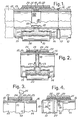
- Fig. 1 shows a tube or pipe connector which is generally designated by 10, and which is used for interconnecting adjacent tube or pipe sections 11 and 12, respectively.
- the connecter 10 comprises a pair of aligned, axially spaced tubular bodies 13 and 14 having oppositely arranged chamfered or bevelled outer edges 15 and 16 which may be connected to the tube or pipe sections 11 and 12, e.g., by weldings 17.
- the spacing 18 defined between the inner ends of the tubular bodies 13 and 14 is covered by a tape or a sheet material 19 which is adhered to the inner surfaces of the tubular bodies 13 and 14, and the spacing 18 is also covered by an outer annular sleeve member 20, which surrounds the adjacent end portions of the bodies 13 and 14.
- the inner diameter of the sleeve member 20 exceeds the outer diameter of the tubular bodies 13 and 14 so as to define an annular space 21 between the inner surface of the sleeve member 20 and the outer surfaces of the tubular bodies 13 and 14.
- the ⁇ spacing 18 between the tubular bodies 13 and 14, and the annular space 21 is completely filled by an intregal annular body 22 of a material comprising the DSP matrix.
- This body 22 interconnects the tubular bodies 13 and 14 and the annular sleeve member 20.
- the electrically insulating body 22 is preferably cast in situ by pouring a material comprising the DSP paste into the space 21.
- the tape or sheet material 19 is preferably electrically insulating. If not, it should be removed when the material comprising the DSP matrix has been cast and has hardened sufficiently.
- Figs. 2 - 4 show further embodiments of the tube or pipe connector, and parts corresponding to those described in connection with Fig. 1 have been designated by the same reference numerals.
- the tape or sheet material 19 has been omitted, and a pair of spacer rings, such as 0-rings, made from an electrically insulating material is arranged on the outer surfaces of the tubular bodies 13 and 14 and their adjacent inner ends.
- the spacer rings 23 may retain the annular sleeve member 20 in the desired radially spaced, coaxial position in relation to the tubular bodies 13 and 14 during casting of the material 22 in the spacing 18 and the annular space 21.
- the casting material may be introduced into the spacing 18 through the inner passage of the tubular body 13 or 14, and the material may be introduced into the annular space 21 from both ends thereof.
- Fig. 3 shows an embodiment in which spacer rings 23 are arranged at the outer ends of the sleeve member 20.
- This sleeve member is provided with an injection opening 24 through which the casting material 22 may be injected into the space defined by the bodies 13 and 14, the tape or sheet material 19, the sleeve member 20, and by the spacer rings 23, by means of a syringe or another injection device 25.
- the embodiment shown in Fig. 4 substantially corresponds to that illustrated in Fig. 1. However, in Fig.
- the inner surface of the sleeve member 20 and the outer surface of the tubular bodies 13 and 14 are provided with projections, such as bosses 26 and/or annular ridges 27 for causing an improved interconnection between the body 22 on one side and the sleeve member 20 and the tubular bodies 13 and 14 on the other.
- the resistivity of the DSP matrix is illustrated in the Example:
- composition of the mixes was as follows :
- the mixing was performed in a kneading machine with planetary movement using a mixing blade. The following procedure was followed:
- samples were cast in polyethylene boxes of dimensions approximately llx9x7 cm with two embedded electrodes of steel wire mesh of dimensions approximately 1.5x1.5 cm and with 1.5 cm between the parallel electrodes. Resistivities were measured with AC at 1 kHz which was shown to be appropriate.
- the electrode arrangement was calibrated in a box of the same dimensions filled with water of known resistivity so the specific resistivity in ⁇ .cm could be calculated from the measured resistance.
- the specimens were cured in water at several different temperatures, and the following resistivities were measured:
Landscapes
- Chemical & Material Sciences (AREA)
- Engineering & Computer Science (AREA)
- Organic Chemistry (AREA)
- Materials Engineering (AREA)
- Inorganic Chemistry (AREA)
- Ceramic Engineering (AREA)
- Structural Engineering (AREA)
- Chemical Kinetics & Catalysis (AREA)
- Mechanical Engineering (AREA)
- Metallurgy (AREA)
- Life Sciences & Earth Sciences (AREA)
- Wood Science & Technology (AREA)
- Curing Cements, Concrete, And Artificial Stone (AREA)
- Preventing Corrosion Or Incrustation Of Metals (AREA)
Applications Claiming Priority (2)
| Application Number | Priority Date | Filing Date | Title |
|---|---|---|---|
| DK303080 | 1980-07-11 | ||
| DK3030/80 | 1980-07-11 |
Publications (1)
| Publication Number | Publication Date |
|---|---|
| EP0044036A1 true EP0044036A1 (de) | 1982-01-20 |
Family
ID=8118337
Family Applications (1)
| Application Number | Title | Priority Date | Filing Date |
|---|---|---|---|
| EP81105310A Withdrawn EP0044036A1 (de) | 1980-07-11 | 1981-07-08 | Gegen Korrosion geschützte Gegenstände und Verfahren zum Korrosionsschutz von Gegenständen |
Country Status (10)
| Country | Link |
|---|---|
| US (1) | US4515861A (de) |
| EP (1) | EP0044036A1 (de) |
| JP (1) | JPH0243697B2 (de) |
| AU (1) | AU7375581A (de) |
| BR (1) | BR8108691A (de) |
| CA (1) | CA1166529A (de) |
| MX (1) | MX156162A (de) |
| NO (1) | NO820765L (de) |
| WO (1) | WO1982000302A1 (de) |
| ZA (1) | ZA814631B (de) |
Cited By (1)
| Publication number | Priority date | Publication date | Assignee | Title |
|---|---|---|---|---|
| WO1996000805A1 (en) * | 1994-06-28 | 1996-01-11 | A.S.W. Limited | Corrosion protection of steel reinforcement in concrete |
Families Citing this family (16)
| Publication number | Priority date | Publication date | Assignee | Title |
|---|---|---|---|---|
| IT1200142B (it) * | 1985-11-08 | 1989-01-05 | Modern Advanced Concrete | Metodo per migliorare la fluidificazione di impasti cementizi |
| US4722952A (en) * | 1986-05-09 | 1988-02-02 | Elkem A/S | Resin compositions |
| US4820196A (en) * | 1987-10-01 | 1989-04-11 | Unisys Corporation | Sealing of contact openings for conformally coated connectors for printed circuit board assemblies |
| DE69124091T2 (de) * | 1990-02-09 | 1997-04-17 | British Tech Group Int | Zusammensetzung zur beschichtung eines substrats |
| WO1995011863A1 (en) * | 1993-10-29 | 1995-05-04 | Union Oil Company Of California | Glass fiber reinforced cement liners for pipelines and casings |
| US6755212B1 (en) | 2001-02-23 | 2004-06-29 | Schwing America, Inc. | Boom stiffening system |
| US6786233B1 (en) | 2001-02-23 | 2004-09-07 | Schwing America, Inc. | Boom utilizing composite material construction |
| US6698451B2 (en) | 2001-02-23 | 2004-03-02 | Schwing America, Inc. | Conveying pipeline mounted inside a boom |
| US6719009B1 (en) | 2001-02-23 | 2004-04-13 | Schwing America, Inc. | Composite material piping system |
| US20030010426A1 (en) * | 2001-07-11 | 2003-01-16 | Lockwood James D. | Method for increasing structural capacity of towers |
| US20030207103A1 (en) * | 2002-05-03 | 2003-11-06 | Zvosec Charles M. | System and method for protecting surfaces against corrosive compounds |
| GB0212687D0 (en) * | 2002-05-31 | 2002-07-10 | Composhield As | Reinforced composite panel |
| US20080155827A1 (en) * | 2004-09-20 | 2008-07-03 | Fyfe Edward R | Method for repairing metal structure |
| DE102005036243A1 (de) * | 2005-08-02 | 2007-02-08 | Wilhelm Karmann Gmbh | Herstellung von Cabriolet-Dächern |
| US8461473B2 (en) * | 2008-10-27 | 2013-06-11 | Wpw, Llc | External corrosion protection for underground pipes |
| US9556076B2 (en) | 2011-11-02 | 2017-01-31 | Empire Technology Development Llc | Salt resistant cement |
Citations (3)
| Publication number | Priority date | Publication date | Assignee | Title |
|---|---|---|---|---|
| DE918859C (de) * | 1951-04-17 | 1954-10-07 | Dyckerhoff & Widmann Ag | Verbesserung des elektrischen Leitwiderstandes von Formkoerpern aus Beton, insbesondere von Eisenbahnschwellen aus Stahlbeton |
| DE2304157A1 (de) * | 1973-01-29 | 1974-08-15 | Waldenmaier J E H | Verfahren zur herstellung korrosionsgeschuetzter metallkoerper und mittel zur durchfuehrung des verfahrens |
| AT354215B (de) * | 1976-05-11 | 1979-12-27 | Lechler Chemie Gmbh | Verfahren und vorrichtung zur herstellung von korrosionsschutzschichten |
Family Cites Families (6)
| Publication number | Priority date | Publication date | Assignee | Title |
|---|---|---|---|---|
| US2890157A (en) * | 1959-06-09 | Method of protecting cells | ||
| JPS5331888B1 (de) * | 1969-09-09 | 1978-09-05 | ||
| US4310486A (en) * | 1976-01-16 | 1982-01-12 | Cornwell Charles E | Compositions of cementitious mortar, grout and concrete |
| US4036659A (en) * | 1976-03-01 | 1977-07-19 | The Dow Chemical Company | Cement composition |
| US4028125A (en) * | 1976-03-25 | 1977-06-07 | The Dow Chemical Company | Cement composition |
| US4255241A (en) * | 1979-05-10 | 1981-03-10 | Kroon David H | Cathodic protection apparatus and method for steel reinforced concrete structures |
-
1981
- 1981-07-08 WO PCT/DK1981/000069 patent/WO1982000302A1/en active Application Filing
- 1981-07-08 EP EP81105310A patent/EP0044036A1/de not_active Withdrawn
- 1981-07-08 AU AU73755/81A patent/AU7375581A/en not_active Abandoned
- 1981-07-08 ZA ZA814631A patent/ZA814631B/xx unknown
- 1981-07-08 JP JP56502573A patent/JPH0243697B2/ja not_active Expired - Lifetime
- 1981-07-08 BR BR8108691A patent/BR8108691A/pt unknown
- 1981-07-08 US US06/359,658 patent/US4515861A/en not_active Expired - Lifetime
- 1981-07-10 CA CA000381549A patent/CA1166529A/en not_active Expired
- 1981-07-13 MX MX188268A patent/MX156162A/es unknown
-
1982
- 1982-03-10 NO NO820765A patent/NO820765L/no unknown
Patent Citations (3)
| Publication number | Priority date | Publication date | Assignee | Title |
|---|---|---|---|---|
| DE918859C (de) * | 1951-04-17 | 1954-10-07 | Dyckerhoff & Widmann Ag | Verbesserung des elektrischen Leitwiderstandes von Formkoerpern aus Beton, insbesondere von Eisenbahnschwellen aus Stahlbeton |
| DE2304157A1 (de) * | 1973-01-29 | 1974-08-15 | Waldenmaier J E H | Verfahren zur herstellung korrosionsgeschuetzter metallkoerper und mittel zur durchfuehrung des verfahrens |
| AT354215B (de) * | 1976-05-11 | 1979-12-27 | Lechler Chemie Gmbh | Verfahren und vorrichtung zur herstellung von korrosionsschutzschichten |
Cited By (1)
| Publication number | Priority date | Publication date | Assignee | Title |
|---|---|---|---|---|
| WO1996000805A1 (en) * | 1994-06-28 | 1996-01-11 | A.S.W. Limited | Corrosion protection of steel reinforcement in concrete |
Also Published As
| Publication number | Publication date |
|---|---|
| CA1166529A (en) | 1984-05-01 |
| JPS57500977A (de) | 1982-06-03 |
| AU7375581A (en) | 1982-02-16 |
| MX156162A (es) | 1988-07-19 |
| NO820765L (no) | 1982-03-10 |
| JPH0243697B2 (de) | 1990-10-01 |
| BR8108691A (pt) | 1982-06-01 |
| US4515861A (en) | 1985-05-07 |
| WO1982000302A1 (en) | 1982-02-04 |
| ZA814631B (en) | 1982-08-25 |
Similar Documents
| Publication | Publication Date | Title |
|---|---|---|
| EP0044036A1 (de) | Gegen Korrosion geschützte Gegenstände und Verfahren zum Korrosionsschutz von Gegenständen | |
| Katz | Bond to concrete of FRP rebars after cyclic loading | |
| US6409433B1 (en) | Foundation piles or similar load carrying elements | |
| Kobayashi et al. | Experimental studies on epoxy coated reinforcing steel for corrosion protection | |
| US4627998A (en) | Carbon fiber reinforced concrete | |
| CN111018463B (zh) | 砂浆补强钢筋混凝土结构 | |
| Darwin et al. | Multiple corrosion protection systems for reinforced concrete bridge components | |
| KR100952458B1 (ko) | 콘크리트용 건조 및 수중 경화 모르타르 및 이를 이용한 보수 보강공법 | |
| Thulasirajan et al. | Studies on coir fibre reinforced bituminous concrete | |
| US20020159843A1 (en) | Foundation piles or similar load carrying elements | |
| WO2009020904A1 (en) | Coated pipe and method using strain-hardening brittle matrix composites | |
| WO2016064324A1 (en) | Concrete mixture and applications of the concrete mixture | |
| CN114407189B (zh) | 输配水用承压管道及制备方法 | |
| CN1194930C (zh) | 接地导电混凝土 | |
| Dash | Strengthening of reinforced concrete beams using glass fiber reinforced polymer composites | |
| US10538383B2 (en) | Protection system for sulfur storage apparatus | |
| EP1504158A1 (de) | Gründungsphäle oder ähnliche lasttragende elemente | |
| US5069822A (en) | Protective coating for reinforced concrete | |
| JP3875601B2 (ja) | 塩害を受けたコンクリート構造物の補修方法 | |
| CN205088677U (zh) | 高性能低预应力混凝土空心方桩 | |
| JP5046276B2 (ja) | コンクリートもしくはモルタル構造物およびコンクリートもしくはモルタル構造物の製造方法 | |
| Palmer | Concrete coating for submarine pipelines | |
| US20220349143A1 (en) | Cementitious slurries, methods, and assemblies for electrically grounding and corrosion-protecting a metallic structure | |
| RU2338117C1 (ru) | Способ изоляции трубопровода | |
| JP6506113B2 (ja) | 鉄筋コンクリート構造物の補修方法 |
Legal Events
| Date | Code | Title | Description |
|---|---|---|---|
| PUAI | Public reference made under article 153(3) epc to a published international application that has entered the european phase |
Free format text: ORIGINAL CODE: 0009012 |
|
| AK | Designated contracting states |
Designated state(s): AT BE CH DE FR GB IT LU NL SE |
|
| 17P | Request for examination filed |
Effective date: 19820707 |
|
| STAA | Information on the status of an ep patent application or granted ep patent |
Free format text: STATUS: THE APPLICATION IS DEEMED TO BE WITHDRAWN |
|
| 18D | Application deemed to be withdrawn |
Effective date: 19850201 |
|
| RIN1 | Information on inventor provided before grant (corrected) |
Inventor name: ARUP, HANS |