EP0043661A2 - Clutch control system - Google Patents
Clutch control system Download PDFInfo
- Publication number
- EP0043661A2 EP0043661A2 EP81302741A EP81302741A EP0043661A2 EP 0043661 A2 EP0043661 A2 EP 0043661A2 EP 81302741 A EP81302741 A EP 81302741A EP 81302741 A EP81302741 A EP 81302741A EP 0043661 A2 EP0043661 A2 EP 0043661A2
- Authority
- EP
- European Patent Office
- Prior art keywords
- error signal
- capacitor
- clutch
- integrator
- engine speed
- Prior art date
- Legal status (The legal status is an assumption and is not a legal conclusion. Google has not performed a legal analysis and makes no representation as to the accuracy of the status listed.)
- Granted
Links
- 239000003990 capacitor Substances 0.000 claims abstract description 23
- 230000001419 dependent effect Effects 0.000 claims abstract 3
- 238000013459 approach Methods 0.000 claims description 7
- 230000005540 biological transmission Effects 0.000 claims description 3
- 238000007493 shaping process Methods 0.000 description 3
- 238000000034 method Methods 0.000 description 1
- 239000000523 sample Substances 0.000 description 1
Images

Classifications
-
- B—PERFORMING OPERATIONS; TRANSPORTING
- B60—VEHICLES IN GENERAL
- B60W—CONJOINT CONTROL OF VEHICLE SUB-UNITS OF DIFFERENT TYPE OR DIFFERENT FUNCTION; CONTROL SYSTEMS SPECIALLY ADAPTED FOR HYBRID VEHICLES; ROAD VEHICLE DRIVE CONTROL SYSTEMS FOR PURPOSES NOT RELATED TO THE CONTROL OF A PARTICULAR SUB-UNIT
- B60W30/00—Purposes of road vehicle drive control systems not related to the control of a particular sub-unit, e.g. of systems using conjoint control of vehicle sub-units
- B60W30/18—Propelling the vehicle
-
- B—PERFORMING OPERATIONS; TRANSPORTING
- B60—VEHICLES IN GENERAL
- B60W—CONJOINT CONTROL OF VEHICLE SUB-UNITS OF DIFFERENT TYPE OR DIFFERENT FUNCTION; CONTROL SYSTEMS SPECIALLY ADAPTED FOR HYBRID VEHICLES; ROAD VEHICLE DRIVE CONTROL SYSTEMS FOR PURPOSES NOT RELATED TO THE CONTROL OF A PARTICULAR SUB-UNIT
- B60W10/00—Conjoint control of vehicle sub-units of different type or different function
- B60W10/02—Conjoint control of vehicle sub-units of different type or different function including control of driveline clutches
-
- B—PERFORMING OPERATIONS; TRANSPORTING
- B60—VEHICLES IN GENERAL
- B60W—CONJOINT CONTROL OF VEHICLE SUB-UNITS OF DIFFERENT TYPE OR DIFFERENT FUNCTION; CONTROL SYSTEMS SPECIALLY ADAPTED FOR HYBRID VEHICLES; ROAD VEHICLE DRIVE CONTROL SYSTEMS FOR PURPOSES NOT RELATED TO THE CONTROL OF A PARTICULAR SUB-UNIT
- B60W10/00—Conjoint control of vehicle sub-units of different type or different function
- B60W10/04—Conjoint control of vehicle sub-units of different type or different function including control of propulsion units
-
- B—PERFORMING OPERATIONS; TRANSPORTING
- B60—VEHICLES IN GENERAL
- B60W—CONJOINT CONTROL OF VEHICLE SUB-UNITS OF DIFFERENT TYPE OR DIFFERENT FUNCTION; CONTROL SYSTEMS SPECIALLY ADAPTED FOR HYBRID VEHICLES; ROAD VEHICLE DRIVE CONTROL SYSTEMS FOR PURPOSES NOT RELATED TO THE CONTROL OF A PARTICULAR SUB-UNIT
- B60W30/00—Purposes of road vehicle drive control systems not related to the control of a particular sub-unit, e.g. of systems using conjoint control of vehicle sub-units
- B60W30/18—Propelling the vehicle
- B60W30/1819—Propulsion control with control means using analogue circuits, relays or mechanical links
-
- F—MECHANICAL ENGINEERING; LIGHTING; HEATING; WEAPONS; BLASTING
- F16—ENGINEERING ELEMENTS AND UNITS; GENERAL MEASURES FOR PRODUCING AND MAINTAINING EFFECTIVE FUNCTIONING OF MACHINES OR INSTALLATIONS; THERMAL INSULATION IN GENERAL
- F16D—COUPLINGS FOR TRANSMITTING ROTATION; CLUTCHES; BRAKES
- F16D48/00—External control of clutches
- F16D48/06—Control by electric or electronic means, e.g. of fluid pressure
- F16D48/066—Control of fluid pressure, e.g. using an accumulator
-
- B—PERFORMING OPERATIONS; TRANSPORTING
- B60—VEHICLES IN GENERAL
- B60W—CONJOINT CONTROL OF VEHICLE SUB-UNITS OF DIFFERENT TYPE OR DIFFERENT FUNCTION; CONTROL SYSTEMS SPECIALLY ADAPTED FOR HYBRID VEHICLES; ROAD VEHICLE DRIVE CONTROL SYSTEMS FOR PURPOSES NOT RELATED TO THE CONTROL OF A PARTICULAR SUB-UNIT
- B60W50/00—Details of control systems for road vehicle drive control not related to the control of a particular sub-unit, e.g. process diagnostic or vehicle driver interfaces
- B60W2050/0001—Details of the control system
- B60W2050/0019—Control system elements or transfer functions
- B60W2050/0022—Gains, weighting coefficients or weighting functions
-
- B—PERFORMING OPERATIONS; TRANSPORTING
- B60—VEHICLES IN GENERAL
- B60W—CONJOINT CONTROL OF VEHICLE SUB-UNITS OF DIFFERENT TYPE OR DIFFERENT FUNCTION; CONTROL SYSTEMS SPECIALLY ADAPTED FOR HYBRID VEHICLES; ROAD VEHICLE DRIVE CONTROL SYSTEMS FOR PURPOSES NOT RELATED TO THE CONTROL OF A PARTICULAR SUB-UNIT
- B60W2510/00—Input parameters relating to a particular sub-units
- B60W2510/02—Clutches
- B60W2510/0208—Clutch engagement state, e.g. engaged or disengaged
- B60W2510/0225—Clutch actuator position
-
- B—PERFORMING OPERATIONS; TRANSPORTING
- B60—VEHICLES IN GENERAL
- B60W—CONJOINT CONTROL OF VEHICLE SUB-UNITS OF DIFFERENT TYPE OR DIFFERENT FUNCTION; CONTROL SYSTEMS SPECIALLY ADAPTED FOR HYBRID VEHICLES; ROAD VEHICLE DRIVE CONTROL SYSTEMS FOR PURPOSES NOT RELATED TO THE CONTROL OF A PARTICULAR SUB-UNIT
- B60W2510/00—Input parameters relating to a particular sub-units
- B60W2510/06—Combustion engines, Gas turbines
- B60W2510/0638—Engine speed
-
- F—MECHANICAL ENGINEERING; LIGHTING; HEATING; WEAPONS; BLASTING
- F16—ENGINEERING ELEMENTS AND UNITS; GENERAL MEASURES FOR PRODUCING AND MAINTAINING EFFECTIVE FUNCTIONING OF MACHINES OR INSTALLATIONS; THERMAL INSULATION IN GENERAL
- F16D—COUPLINGS FOR TRANSMITTING ROTATION; CLUTCHES; BRAKES
- F16D2500/00—External control of clutches by electric or electronic means
- F16D2500/10—System to be controlled
- F16D2500/104—Clutch
- F16D2500/10406—Clutch position
- F16D2500/10412—Transmission line of a vehicle
-
- F—MECHANICAL ENGINEERING; LIGHTING; HEATING; WEAPONS; BLASTING
- F16—ENGINEERING ELEMENTS AND UNITS; GENERAL MEASURES FOR PRODUCING AND MAINTAINING EFFECTIVE FUNCTIONING OF MACHINES OR INSTALLATIONS; THERMAL INSULATION IN GENERAL
- F16D—COUPLINGS FOR TRANSMITTING ROTATION; CLUTCHES; BRAKES
- F16D2500/00—External control of clutches by electric or electronic means
- F16D2500/10—System to be controlled
- F16D2500/104—Clutch
- F16D2500/10443—Clutch type
- F16D2500/1045—Friction clutch
-
- F—MECHANICAL ENGINEERING; LIGHTING; HEATING; WEAPONS; BLASTING
- F16—ENGINEERING ELEMENTS AND UNITS; GENERAL MEASURES FOR PRODUCING AND MAINTAINING EFFECTIVE FUNCTIONING OF MACHINES OR INSTALLATIONS; THERMAL INSULATION IN GENERAL
- F16D—COUPLINGS FOR TRANSMITTING ROTATION; CLUTCHES; BRAKES
- F16D2500/00—External control of clutches by electric or electronic means
- F16D2500/30—Signal inputs
- F16D2500/306—Signal inputs from the engine
- F16D2500/3067—Speed of the engine
-
- F—MECHANICAL ENGINEERING; LIGHTING; HEATING; WEAPONS; BLASTING
- F16—ENGINEERING ELEMENTS AND UNITS; GENERAL MEASURES FOR PRODUCING AND MAINTAINING EFFECTIVE FUNCTIONING OF MACHINES OR INSTALLATIONS; THERMAL INSULATION IN GENERAL
- F16D—COUPLINGS FOR TRANSMITTING ROTATION; CLUTCHES; BRAKES
- F16D2500/00—External control of clutches by electric or electronic means
- F16D2500/50—Problem to be solved by the control system
- F16D2500/52—General
- F16D2500/525—Improve response of control system
-
- F—MECHANICAL ENGINEERING; LIGHTING; HEATING; WEAPONS; BLASTING
- F16—ENGINEERING ELEMENTS AND UNITS; GENERAL MEASURES FOR PRODUCING AND MAINTAINING EFFECTIVE FUNCTIONING OF MACHINES OR INSTALLATIONS; THERMAL INSULATION IN GENERAL
- F16D—COUPLINGS FOR TRANSMITTING ROTATION; CLUTCHES; BRAKES
- F16D2500/00—External control of clutches by electric or electronic means
- F16D2500/70—Details about the implementation of the control system
- F16D2500/706—Strategy of control
- F16D2500/70605—Adaptive correction; Modifying control system parameters, e.g. gains, constants, look-up tables
-
- F—MECHANICAL ENGINEERING; LIGHTING; HEATING; WEAPONS; BLASTING
- F16—ENGINEERING ELEMENTS AND UNITS; GENERAL MEASURES FOR PRODUCING AND MAINTAINING EFFECTIVE FUNCTIONING OF MACHINES OR INSTALLATIONS; THERMAL INSULATION IN GENERAL
- F16D—COUPLINGS FOR TRANSMITTING ROTATION; CLUTCHES; BRAKES
- F16D2500/00—External control of clutches by electric or electronic means
- F16D2500/70—Details about the implementation of the control system
- F16D2500/706—Strategy of control
- F16D2500/7061—Feed-back
Definitions
- This invention relates to electronic clutch control systems for the automatic control of friction clutches between the engine and transmission of motor vehicles.
- a problem that we have encountered is that during clutch take up there is a time delay between the error signal reaching a predetermined trigger point and the clutch mechanism coming into operation.
- the present invention seeks to provide an electronic control for the clutch operating mechanism in which the time delay is reduced.
- an electronic control system for a rotary transmission clutch which has an engine speed sensor and signal means, a reference signal generator, a clutch actuator responsive to an error signal derived from comparison of the engine speed and reference signals, and an integrator located in the error signal path before the actuator wherein the integrator has a capacitor for switching in and out of the error signal circuit dependant upon the value of the error signal so that the integrator has two response modes for control of the actuator depending upon whether the capacitor is in or out of the circuit.
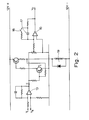
- the motor vehicle engine speed is sensed by a sensor 11 that produces a voltage V 1 proportional to the engine speed.
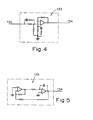
- the electrical circuit of the sensor is illustrated in Fig. 3 and is basically a magnetic probe sensing the teeth on the engine flywheel and a transistor pump.
- the sensor 11 is connected to a comparator 13 which measures the difference between the voltage v 1 and a voltage V R received from a reference voltage generator 14.
- This can for example be a potentiometer across the vehicle battery and can be set so that the reference voltage is the same as a signal obtained via the sensor 11 at a particular engine speed eg. 1000 rpm.
- An error signal E from the comparator 13 is fed into an inverting integrator 15 which is in turn connected to a clutch position control which controls the operation of an actuator 27.
- the actuator 27 operates the vehicle clutch 23 and is powered by hydraulic pressure but could alternatively be pneumatic or electrical.
- the clutch position control comprises a comparator 130 that receives a command signal V c from the integrator 15 and a feed back signal Vp from a travel transducer 132 responsive to the clutch position.
- the feed back signal Vp is representative of the position of the clutch 23.
- the signal derived from the comparator 130 is fed into a phase gain shaping network 133, a mark space ratio modulator and oscillator 134 and 135 respectively, and is then utilised via output 138 to control a solenoid operated hydraulic valve 136.
- the hydraulic valve 136 controls hydraulic flow through the hydraulic actuator 27.
- the mark space ratio of the signal fed into the solenoid valve 136 determines the hydraulic flow into the actuator and hence the rate of engagement of the clutch driven plate with its driving member.
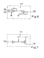
- the shaping network 133, oscillator 135, mark space ratio network 134, and output are shown in detail in Figs. 4 to 7 respectively.
- the actuator 27 operates so as to equalise the feed back signal Vp to the comparator 130, with the command signal V c from the integrator 15 consequently the actuator 27 takes up a position dictated by the command signal V C and which is proportional to the value of the command signal V C , which in turn is responsive to the error signal E.
- the clutch position control operates the actuator 27 during clutch take up to vary the state of engagement of the clutch driven plate with a driving member on the vehicle engine (not shown) and thereby alter the engine speed to cause the engine speed signal V 1 to approach equivalence with the reference signal V R and make the error signal E approach zero.
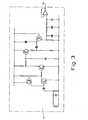
- the error signal is fed to an integrator 15 which has a capacitor 17 that can be by passed through a resistor 20 when a switch 18 is closed.
- the switch 18 is operated by a relay 19 which is responsive to the approach of the error signal E to zero and becoming negative. With the error signal positive the switch 18 is closed and there is approximately unity gain in the integrator 15 so that the error signal E is equal to the command signal V C . When the error signal is negative the switch 18 is open and the capacitor 17 is placed in the error signal path the gain of the integrator 15 produces an amplified command signal V C .
- the relay 19 causes the switch 18 to open placing the capacitor 17 in operation across the integrator 15, increasing the gain. Because the integrator 15 is an inverting integrator then with the capacitor 17 by passed there is no build up of charge across the capacitor. Therefore, when the error signal E changes its polarity as V 1 approaches zero and then exceeds V R there is no time delay as the charge on the capacitor reverses its polarity ie. if there had been a charge on the capacitor some delay would be experienced as the capacitor discharged before reversing its polarity.
- the integrator 15 and its switching circuit are shown in more detail in Fig. 2.
- E When E is positive the transistor T 1 is on and causes the relay 19 to close its contacts 18.
- E goes zero or negative the transistor T 1 switches off and the contacts 18 are open so that the capacitor 17 is switched into the control loop circuit and the integrator 15 is given a high gain.
- the driver recognises the fall in engine speed and increases the throttle opening hence increasing V 1 which causes the clutch to further engage. This process of increasing the throttle opening and holding the engine speed steady by further engagement of the clutch will continue until the clutch is fully engaged.
Landscapes
- Engineering & Computer Science (AREA)
- Mechanical Engineering (AREA)
- General Engineering & Computer Science (AREA)
- Chemical & Material Sciences (AREA)
- Combustion & Propulsion (AREA)
- Transportation (AREA)
- Physics & Mathematics (AREA)
- Fluid Mechanics (AREA)
- Automation & Control Theory (AREA)
- Hydraulic Clutches, Magnetic Clutches, Fluid Clutches, And Fluid Joints (AREA)
- Arrangement And Mounting Of Devices That Control Transmission Of Motive Force (AREA)
- Control Of Driving Devices And Active Controlling Of Vehicle (AREA)
Abstract
Description
- This invention relates to electronic clutch control systems for the automatic control of friction clutches between the engine and transmission of motor vehicles.
- In our earlier Application No. we have described a clutch control apparatus in which the engagement of the friction clutch is controlled by electronic means. In this earlier application there is described a control having an engine speed sensor and signal means, and a reference signal generator. An error signal for controlling the clutch take up is derived from the reference and engine speed signals. The error signal controls the operation of a clutch control system for the engagement of a clutch driven plate with its driving member.
- A problem that we have encountered is that during clutch take up there is a time delay between the error signal reaching a predetermined trigger point and the clutch mechanism coming into operation.
- The present invention seeks to provide an electronic control for the clutch operating mechanism in which the time delay is reduced.
- Accordingly there is provided an electronic control system for a rotary transmission clutch which has an engine speed sensor and signal means, a reference signal generator, a clutch actuator responsive to an error signal derived from comparison of the engine speed and reference signals, and an integrator located in the error signal path before the actuator wherein the integrator has a capacitor for switching in and out of the error signal circuit dependant upon the value of the error signal so that the integrator has two response modes for control of the actuator depending upon whether the capacitor is in or out of the circuit.
- The invention will be described by way of example and with reference to the accompanying drawings in which:-
- Fig. 1 is a schematic drawing of a clutch control system according to this invention;
- Fig. 2 is a detailed drawing of the circuit for the integrator and its controlling relay;
- Fig. 3 is a detailed circuit of an engine speed sensor as used in Fig. 1;
- Fig. 4 is a detailed circuit of the phase gain shaping network utilised in Fig. 1;
- Fig. 5 is a detailed circuit of the oscillator of Fig. 1;
- Fig. 6 is a detailed circuit of the mark space ratio modulator of Fig. 1; and
- Fig. 7 is an output as used in Fig. 1.
- The motor vehicle engine speed is sensed by a
sensor 11 that produces a voltage V1 proportional to the engine speed. The electrical circuit of the sensor is illustrated in Fig. 3 and is basically a magnetic probe sensing the teeth on the engine flywheel and a transistor pump. Thesensor 11 is connected to acomparator 13 which measures the difference between the voltage v1 and a voltage VR received from areference voltage generator 14. This can for example be a potentiometer across the vehicle battery and can be set so that the reference voltage is the same as a signal obtained via thesensor 11 at a particular engine speed eg. 1000 rpm. - An error signal E from the
comparator 13 is fed into an invertingintegrator 15 which is in turn connected to a clutch position control which controls the operation of anactuator 27. Theactuator 27 operates thevehicle clutch 23 and is powered by hydraulic pressure but could alternatively be pneumatic or electrical. - The clutch position control comprises a
comparator 130 that receives a command signal Vc from theintegrator 15 and a feed back signal Vp from a travel transducer 132 responsive to the clutch position. The feed back signal Vp is representative of the position of theclutch 23. The signal derived from thecomparator 130 is fed into a phasegain shaping network 133, a mark space ratio modulator andoscillator output 138 to control a solenoid operatedhydraulic valve 136. Thehydraulic valve 136 controls hydraulic flow through thehydraulic actuator 27. The mark space ratio of the signal fed into thesolenoid valve 136 determines the hydraulic flow into the actuator and hence the rate of engagement of the clutch driven plate with its driving member. Theshaping network 133,oscillator 135, markspace ratio network 134, and output are shown in detail in Figs. 4 to 7 respectively. - The
actuator 27 operates so as to equalise the feed back signal Vp to thecomparator 130, with the command signal Vc from theintegrator 15 consequently theactuator 27 takes up a position dictated by the command signal VC and which is proportional to the value of the command signal VC, which in turn is responsive to the error signal E. - The clutch position control operates the
actuator 27 during clutch take up to vary the state of engagement of the clutch driven plate with a driving member on the vehicle engine (not shown) and thereby alter the engine speed to cause the engine speed signal V1 to approach equivalence with the reference signal VR and make the error signal E approach zero. - When the engine speed signal V1 is lower than the reference signal VR the error signal E is positive and the clutch disengaged. When the signal V1 exceeds VR the error signal becomes negative and the clutch loads the vehicle engine to cause the engine speed to decrease and mark V1 = VR at which point the error signal tends to approach zero. Hence for a given throttle opening during clutch take up the clutch engagement will arrive at the condition where V1 = VR. Once the clutch is fully engaged the engine speed can rise above the reference and the clutch control will hold the clutch fully engaged.
- The error signal is fed to an
integrator 15 which has acapacitor 17 that can be by passed through aresistor 20 when aswitch 18 is closed. Theswitch 18 is operated by arelay 19 which is responsive to the approach of the error signal E to zero and becoming negative. With the error signal positive theswitch 18 is closed and there is approximately unity gain in theintegrator 15 so that the error signal E is equal to the command signal VC. When the error signal is negative theswitch 18 is open and thecapacitor 17 is placed in the error signal path the gain of theintegrator 15 produces an amplified command signal VC. During the period for which the error signal is positive and the integrator has unity gain the position of the clutch is dictated by the value of the error signal. At the point where E =.0 the clutch is in position where it is just beginning to engage with the engine, and theintegrator 15 has a high gain and thereafter the velocity of the clutch is proportionaltothe error signal. - When the vehicle is started and the engine speed idling, the engine speed signal V1 is less than the reference signal VR giving rise to a positive error signal E. The position of the clutch plate is inversely proportional to the size of the error signal E so that as the engine speed increases and V1 increases, the error signal tends to zero. Since the contacts of the
switch 18 are closed and Vc is equal to E, then the clutch driven plate moves slowly into engagement with the engine driving member as E → 0. - At the point where V1 equals VR the error signal goes to zero and then negative as V1 exceeds VR, the
relay 19 causes theswitch 18 to open placing thecapacitor 17 in operation across theintegrator 15, increasing the gain. Because theintegrator 15 is an inverting integrator then with thecapacitor 17 by passed there is no build up of charge across the capacitor. Therefore, when the error signal E changes its polarity as V1 approaches zero and then exceeds VR there is no time delay as the charge on the capacitor reverses its polarity ie. if there had been a charge on the capacitor some delay would be experienced as the capacitor discharged before reversing its polarity. - Further, there is some delay in the period between the engine speed signal overshooting the value of VR and the clutch engagement pulling the engine speed back down to V1 = VR. By increasing the gain across the
integrator 15 the period of delay between the error signal deviating from zero value and theclutch actuator 27 responding to move the clutch to a position where V1 = VR is greatly reduced. - The
integrator 15 and its switching circuit are shown in more detail in Fig. 2. When E is positive the transistor T1 is on and causes therelay 19 to close itscontacts 18. When E goes zero or negative the transistor T1 switches off and thecontacts 18 are open so that thecapacitor 17 is switched into the control loop circuit and theintegrator 15 is given a high gain. - The error signal E going to zero and negative activates the clutch position control to operate the
actuator 27 to begin to engage the clutch plate with its driving member to increase the torque load on the engine and replace the engine speed to make V1 = VR. The driver recognises the fall in engine speed and increases the throttle opening hence increasing V1 which causes the clutch to further engage. This process of increasing the throttle opening and holding the engine speed steady by further engagement of the clutch will continue until the clutch is fully engaged.
Claims (5)
Applications Claiming Priority (2)
| Application Number | Priority Date | Filing Date | Title |
|---|---|---|---|
| GB8022347 | 1980-07-08 | ||
| GB8022347 | 1980-07-08 |
Publications (3)
| Publication Number | Publication Date |
|---|---|
| EP0043661A2 true EP0043661A2 (en) | 1982-01-13 |
| EP0043661A3 EP0043661A3 (en) | 1983-07-20 |
| EP0043661B1 EP0043661B1 (en) | 1985-10-09 |
Family
ID=10514609
Family Applications (1)
| Application Number | Title | Priority Date | Filing Date |
|---|---|---|---|
| EP81302741A Expired EP0043661B1 (en) | 1980-07-08 | 1981-06-18 | Clutch control system |
Country Status (9)
| Country | Link |
|---|---|
| US (1) | US4413714A (en) |
| EP (1) | EP0043661B1 (en) |
| JP (1) | JPS5747220A (en) |
| AU (1) | AU546622B2 (en) |
| BR (1) | BR8104328A (en) |
| DE (1) | DE3172588D1 (en) |
| ES (1) | ES8204100A1 (en) |
| GB (1) | GB2079889B (en) |
| MX (1) | MX149735A (en) |
Cited By (4)
| Publication number | Priority date | Publication date | Assignee | Title |
|---|---|---|---|---|
| FR2563169A1 (en) * | 1984-01-24 | 1985-10-25 | Lucas Ind Plc | CONTROL APPARATUS FOR THE TRANSMISSION OF A VEHICLE |
| FR2581058A1 (en) * | 1985-04-24 | 1986-10-31 | Valeo | METHOD OF AUTOMATICALLY MANEUVERING A CLUTCH ROD ACCORDING TO THE SPEEDS OF TREES COUPLED BY AN ASSOCIATED CLUTCH |
| FR2686552A1 (en) * | 1992-01-28 | 1993-07-30 | Fichtel & Sachs Ag | DEVICE FOR ACTUATING A FRICTION CLUTCH OF A MOTOR VEHICLE DRIVEN BY AN INTERNAL COMBUSTION ENGINE. |
| EP0638454A1 (en) * | 1993-08-10 | 1995-02-15 | Dr.Ing.h.c. F. Porsche Aktiengesellschaft | Control system for torque transfer means in vehicle driveline |
Families Citing this family (16)
| Publication number | Priority date | Publication date | Assignee | Title |
|---|---|---|---|---|
| DE3214494A1 (en) * | 1982-04-20 | 1983-10-20 | Sachs Systemtechnik Gmbh, 8720 Schweinfurt | DEVICE FOR AUTOMATICALLY OPERATING A MOTOR VEHICLE FRICTION CLUTCH |
| AU1725283A (en) * | 1982-08-11 | 1984-02-16 | Automotive Products Plc | Clutch control system |
| JPH0623023B2 (en) * | 1984-01-30 | 1994-03-30 | 富士重工業株式会社 | Control device for electromagnetic clutch for vehicle |
| USRE34023E (en) * | 1984-03-30 | 1992-08-11 | Dana Corporation | Power takeoff speed control assembly |
| US4597047A (en) * | 1984-07-13 | 1986-06-24 | Motorola, Inc. | Engine control system including engine idle speed control |
| US4558772A (en) * | 1984-08-29 | 1985-12-17 | General Motors Corporation | Electronic control for a starting clutch |
| JP2564508B2 (en) * | 1985-04-30 | 1996-12-18 | 日産自動車株式会社 | Start clutch control device for automatic transmission |
| US4638898A (en) * | 1985-12-19 | 1987-01-27 | Eaton Corporation | Clutch control system and clutch assembly using same |
| US4807130A (en) * | 1986-12-24 | 1989-02-21 | Motorola, Inc. | Servo control system for transmission shaft speed control |
| US4874070A (en) * | 1988-02-10 | 1989-10-17 | Eaton Corporation | Control for AMT system start from stop operation |
| US4883037A (en) * | 1988-02-17 | 1989-11-28 | Automotive Products Plc | Throttle control system |
| US4831985A (en) * | 1988-02-17 | 1989-05-23 | Mabee Brian D | Throttle control system |
| US4899858A (en) * | 1989-03-02 | 1990-02-13 | Eaton Corporation | Method and control system for updating of control parameter value indicative of master clutch point of incipient engagement |
| GB9101164D0 (en) * | 1991-01-18 | 1991-02-27 | Automotive Prod Plc | Clutch control system |
| JP3572623B2 (en) * | 1992-08-31 | 2004-10-06 | 本田技研工業株式会社 | Control device for vehicle clutch |
| JPH09303424A (en) * | 1996-05-21 | 1997-11-25 | Mitsubishi Electric Corp | Automobile clutch control device |
Citations (3)
| Publication number | Priority date | Publication date | Assignee | Title |
|---|---|---|---|---|
| GB1120132A (en) * | 1964-11-27 | 1968-07-17 | Smiths Industries Ltd | Improvements in automatic clutch engagement |
| US3673400A (en) * | 1969-06-09 | 1972-06-27 | Nippon Denso Co | Slip ratio calculating device |
| US4081065A (en) * | 1976-12-23 | 1978-03-28 | Smyth Robert Ralston | Controlled power clutch |
Family Cites Families (7)
| Publication number | Priority date | Publication date | Assignee | Title |
|---|---|---|---|---|
| US3622208A (en) * | 1970-01-09 | 1971-11-23 | Ford Motor Co | Analog circuit for detecting deviations from a predetermined percentage wheel slip in an antiskid brake system |
| US3709340A (en) * | 1970-04-27 | 1973-01-09 | Aisin Seiki | Fluid released clutch controlled by engine speed and gear shifter |
| US3714509A (en) * | 1971-05-07 | 1973-01-30 | Production Technology Inc | Inertia welder speed control device |
| JPS49122382A (en) * | 1973-03-22 | 1974-11-22 | ||
| JPS52127559A (en) * | 1976-04-19 | 1977-10-26 | Nissan Motor Co Ltd | Electronic parallel shaft automatic transmission gear box |
| DE2657524C3 (en) * | 1976-12-18 | 1981-07-23 | Voith Getriebe Kg, 7920 Heidenheim | Control device for a main clutch for motor vehicles that can be disengaged by a hydraulic actuating cylinder |
| US4352403A (en) * | 1979-03-22 | 1982-10-05 | Travel Accessories Manufacturing Co., Inc. | Vehicle speed control system |
-
1981
- 1981-06-18 DE DE8181302741T patent/DE3172588D1/en not_active Expired
- 1981-06-18 EP EP81302741A patent/EP0043661B1/en not_active Expired
- 1981-06-22 AU AU72037/81A patent/AU546622B2/en not_active Ceased
- 1981-06-24 GB GB8119505A patent/GB2079889B/en not_active Expired
- 1981-06-24 MX MX187975A patent/MX149735A/en unknown
- 1981-06-30 US US06/279,084 patent/US4413714A/en not_active Expired - Fee Related
- 1981-07-07 BR BR8104328A patent/BR8104328A/en unknown
- 1981-07-07 JP JP56106167A patent/JPS5747220A/en active Granted
- 1981-07-07 ES ES503722A patent/ES8204100A1/en not_active Expired
Patent Citations (3)
| Publication number | Priority date | Publication date | Assignee | Title |
|---|---|---|---|---|
| GB1120132A (en) * | 1964-11-27 | 1968-07-17 | Smiths Industries Ltd | Improvements in automatic clutch engagement |
| US3673400A (en) * | 1969-06-09 | 1972-06-27 | Nippon Denso Co | Slip ratio calculating device |
| US4081065A (en) * | 1976-12-23 | 1978-03-28 | Smyth Robert Ralston | Controlled power clutch |
Cited By (6)
| Publication number | Priority date | Publication date | Assignee | Title |
|---|---|---|---|---|
| FR2563169A1 (en) * | 1984-01-24 | 1985-10-25 | Lucas Ind Plc | CONTROL APPARATUS FOR THE TRANSMISSION OF A VEHICLE |
| FR2581058A1 (en) * | 1985-04-24 | 1986-10-31 | Valeo | METHOD OF AUTOMATICALLY MANEUVERING A CLUTCH ROD ACCORDING TO THE SPEEDS OF TREES COUPLED BY AN ASSOCIATED CLUTCH |
| US4712658A (en) * | 1985-04-24 | 1987-12-15 | Valeo | Method of automatically operating a clutch release bearing according to the speeds of the shafts coupled by an associated clutch |
| FR2686552A1 (en) * | 1992-01-28 | 1993-07-30 | Fichtel & Sachs Ag | DEVICE FOR ACTUATING A FRICTION CLUTCH OF A MOTOR VEHICLE DRIVEN BY AN INTERNAL COMBUSTION ENGINE. |
| EP0638454A1 (en) * | 1993-08-10 | 1995-02-15 | Dr.Ing.h.c. F. Porsche Aktiengesellschaft | Control system for torque transfer means in vehicle driveline |
| US5491635A (en) * | 1993-08-10 | 1996-02-13 | Dr. Ing. H.C.F. Porsche Ag | Arrangement and a process for controlling a starting device of a vehicle drive |
Also Published As
| Publication number | Publication date |
|---|---|
| JPS5747220A (en) | 1982-03-18 |
| DE3172588D1 (en) | 1985-11-14 |
| AU7203781A (en) | 1982-01-14 |
| US4413714A (en) | 1983-11-08 |
| EP0043661A3 (en) | 1983-07-20 |
| BR8104328A (en) | 1982-03-23 |
| ES503722A0 (en) | 1982-04-16 |
| JPS647897B2 (en) | 1989-02-10 |
| GB2079889B (en) | 1983-12-07 |
| MX149735A (en) | 1983-12-14 |
| ES8204100A1 (en) | 1982-04-16 |
| AU546622B2 (en) | 1985-09-12 |
| GB2079889A (en) | 1982-01-27 |
| EP0043661B1 (en) | 1985-10-09 |
Similar Documents
| Publication | Publication Date | Title |
|---|---|---|
| EP0043661B1 (en) | Clutch control system | |
| US4418810A (en) | Clutch control system | |
| EP0059035B1 (en) | Clutch control system | |
| EP0038113B1 (en) | Clutch control apparatus | |
| US4488625A (en) | Clutch control system for automobiles | |
| US4432445A (en) | Clutch control systems | |
| US4374422A (en) | Automatic speed control for heavy vehicles | |
| US4529072A (en) | Automatic clutch control system | |
| EP0051004B1 (en) | Automatic speed control system for a heavy vehicle | |
| US4098242A (en) | Automatic control system with gain switching | |
| SU1210655A3 (en) | Electronic system for controlling vehicle transmission | |
| GB1427039A (en) | Automatic clutch mechanism | |
| JPS6350216B2 (en) | ||
| US4535879A (en) | Control system for controlling the engagement of a pressure-operated actuator | |
| JPH0555332B2 (en) | ||
| SU1179915A3 (en) | System for controlling vehicle transmission engagement | |
| US4475073A (en) | Proportional plus integral servo-reversible speed control | |
| US4210853A (en) | Control device with an integrating position drive | |
| US4785903A (en) | Arrangement for the propulsion regulation of motor vehicles | |
| JPH0623028B2 (en) | Automatic clutch control device | |
| JPH0155324B2 (en) | ||
| RU1837021C (en) | Traction unit two-production electro-mechanical transmission | |
| SU1382679A1 (en) | Arrangement for automatic control of vehicle clutch in field tests | |
| SU1719561A1 (en) | Device for controlling electrical drives of single-bucket excavator mechanisms | |
| GB1241062A (en) | Improvements relating to speed control systems |
Legal Events
| Date | Code | Title | Description |
|---|---|---|---|
| PUAI | Public reference made under article 153(3) epc to a published international application that has entered the european phase |
Free format text: ORIGINAL CODE: 0009012 |
|
| AK | Designated contracting states |
Designated state(s): AT BE DE FR GB IT NL SE |
|
| 17P | Request for examination filed |
Effective date: 19820316 |
|
| RAP1 | Party data changed (applicant data changed or rights of an application transferred) |
Owner name: AUTOMOTIVE PRODUCTS PUBLIC LIMITED COMPANY |
|
| PUAL | Search report despatched |
Free format text: ORIGINAL CODE: 0009013 |
|
| RHK1 | Main classification (correction) |
Ipc: B60K 41/02 |
|
| AK | Designated contracting states |
Designated state(s): AT BE DE FR GB IT NL SE |
|
| RBV | Designated contracting states (corrected) |
Designated state(s): AT BE DE FR IT NL SE |
|
| ITF | It: translation for a ep patent filed | ||
| RBV | Designated contracting states (corrected) |
Designated state(s): DE FR IT SE |
|
| GRAA | (expected) grant |
Free format text: ORIGINAL CODE: 0009210 |
|
| AK | Designated contracting states |
Designated state(s): DE FR IT SE |
|
| REF | Corresponds to: |
Ref document number: 3172588 Country of ref document: DE Date of ref document: 19851114 |
|
| ET | Fr: translation filed | ||
| PLBE | No opposition filed within time limit |
Free format text: ORIGINAL CODE: 0009261 |
|
| STAA | Information on the status of an ep patent application or granted ep patent |
Free format text: STATUS: NO OPPOSITION FILED WITHIN TIME LIMIT |
|
| 26N | No opposition filed | ||
| PG25 | Lapsed in a contracting state [announced via postgrant information from national office to epo] |
Ref country code: SE Effective date: 19870619 |
|
| PG25 | Lapsed in a contracting state [announced via postgrant information from national office to epo] |
Ref country code: DE Effective date: 19880301 |
|
| PGFP | Annual fee paid to national office [announced via postgrant information from national office to epo] |
Ref country code: FR Payment date: 19900510 Year of fee payment: 10 |
|
| PG25 | Lapsed in a contracting state [announced via postgrant information from national office to epo] |
Ref country code: FR Effective date: 19920228 |
|
| REG | Reference to a national code |
Ref country code: FR Ref legal event code: ST |
|
| EUG | Se: european patent has lapsed |
Ref document number: 81302741.4 Effective date: 19880712 |