EP0042786B1 - Outil de fixation pour colliers de serrage - Google Patents
Outil de fixation pour colliers de serrage Download PDFInfo
- Publication number
- EP0042786B1 EP0042786B1 EP19810400962 EP81400962A EP0042786B1 EP 0042786 B1 EP0042786 B1 EP 0042786B1 EP 19810400962 EP19810400962 EP 19810400962 EP 81400962 A EP81400962 A EP 81400962A EP 0042786 B1 EP0042786 B1 EP 0042786B1
- Authority
- EP
- European Patent Office
- Prior art keywords
- tool
- movable member
- clamp
- stop member
- shoe
- Prior art date
- Legal status (The legal status is an assumption and is not a legal conclusion. Google has not performed a legal analysis and makes no representation as to the accuracy of the status listed.)
- Expired
Links
- 238000006073 displacement reaction Methods 0.000 claims 2
- 239000002184 metal Substances 0.000 description 3
- 230000000295 complement effect Effects 0.000 description 2
- 230000000694 effects Effects 0.000 description 1
- 210000000003 hoof Anatomy 0.000 description 1
- 239000002699 waste material Substances 0.000 description 1
Images

Classifications
-
- B—PERFORMING OPERATIONS; TRANSPORTING
- B25—HAND TOOLS; PORTABLE POWER-DRIVEN TOOLS; MANIPULATORS
- B25B—TOOLS OR BENCH DEVICES NOT OTHERWISE PROVIDED FOR, FOR FASTENING, CONNECTING, DISENGAGING OR HOLDING
- B25B25/00—Implements for fastening, connecting or tensioning of wire or strip
- B25B25/005—Implements for fastening, connecting or tensioning of wire or strip for applying wire clasps to hose couplings
Definitions
- the invention relates to a tool, in particular a portable tool, for fixing such a collar to the object to be tightened, such as for example a rubber hose fitted on a rigid tube in order to obtain a high rate of setting. in place of the collar and to ensure a predetermined tightening thereof.
- the invention therefore relates to a tool of the kind which has just been briefly recalled, specially adapted for fixing the clamps comprising two stops, more particularly clamps of the type described in the patent mentioned above.
- the movable member of the tool is preferably coupled to a motor such as for example a hydraulic cylinder and comprises at its active end, an articulated nose whose or shoulder comes into contact during the movement of the 'movable member, with that of the collar stops intended to be torn off, and first causes the clamping of the collar and then the tearing of said stop.
- a motor such as for example a hydraulic cylinder and comprises at its active end, an articulated nose whose or shoulder comes into contact during the movement of the 'movable member, with that of the collar stops intended to be torn off, and first causes the clamping of the collar and then the tearing of said stop.
- the theoretical travel of the movable member from its rest position to its final position is at least equal, and preferably substantially greater, to the travel necessary to ensure proper tightening of the collar and to cause tearing of the stop when the belt tension exceeds a predetermined value.
- the tool is of very simple design, its weight and its length remaining fairly low, which facilitates its use for mounting collars in series, in particular in the automobile industry.
- the tool has a general shape similar to that of a pistol whose body 1 has a stock 2 intended for handling. Inside the body is slidably mounted a movable member 3 whose straight end, considered as the rear end, is coupled to a motor not shown.
- This motor will preferably be a pneumatic cylinder housed at the rear of the body 1 and controlled by a trigger 4 or the like placed on the stock 2.
- the motor When the motor is controlled, it causes the movable member 3 to move to the right of the figure, that is to say towards the rear of the tool, the return of the movable member to the rest position (shown in solid lines in FIG. 1) being ensured by any appropriate means, for example by a spring incorporated in the jack.
- the collar to be tightened consists essentially of a metal band wound on itself, the two strands 5a and 5b having complementary hooking teeth on their opposite faces.
- a clip 6 encloses the two strands 5a and 5b and thus prevents the teeth from being accidentally detached from each other, after the collar has been put in place.
- the strand 5a has a first stop 7 generally obtained by a deformation of the metal strip, while the strand 5b has a second stop 8 of a similar type and described in detail in the aforementioned patent.
- the two stops 7 and 8 are located on the outer faces of the strands and on the same side relative to the clip 6, the second stop 8 is preferably very close to the free end of the strand 5b.
- a shoe 1 a secured to the body.
- this shoe is removable by means of screws 9.
- a determined shoe is adapted to the diameter of the collar to be tightened and has a curved surface 1b on which the collar can hang.
- this shoe has at the front a support surface 1 c for the first stop 7 of the collar.
- the front end of the movable member 3 is constituted by a nose 10 articulated around an axis 11 parallel to the axis of the collar.
- the nose 10 In its rest position, shown in solid lines in Figure 1, the nose 10 is engaged in a housing 12 formed at the front end of the body 1.
- the general direction of this housing is inclined upwards and towards the front relative to the longitudinal axis of the movable member 3 for reasons which will appear later.
- the front end of the body further comprises, below the housing 12, a small shoe 13, removable and interchangeable, the lower face 13a of which constitutes a support for the outer face of the strand 5b.
- the nose 10 has a shoulder 10a, or the like, projecting mainly from the rear towards the front of the tool; its role will appear later.
- a groove 14 is formed in the body of the tool between the movable member 3 and the shoe 1 a and extends rearward from the front end of the shoe 1 a over a length at least equal to the stroke of the movable member. It opens into a conduit 15 open to the outside and possibly connected to a waste collector for reasons which will appear later.
- the nose 10 comprises behind the shoulder 10a a retractable elastic member located at the entrance to the groove 14.
- this member is constituted by a bent blade 16 fixed in the hollow of the shoulder and directed backwards and downwards when the tool is in its rest position. The operation of the tool is then as follows.
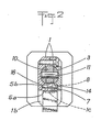
- the strand 5b of the collar is introduced at the entrance to the groove 14 until the stop 7 comes into contact with the bearing surface 1 c of the shoe. During this movement, the strand 5b and its boss 8 have raised the elastic blade 1 6 whose bent end can then bear behind the boss 8; the collar is thus held in the tool and can, if it is not already done, be fitted on the object to be tightened.
- the cooperation of the strand 5b with the sides of the groove 14 maintains the latter without a correct position (fig. 2).
- the nose 10 has left its housing 12 and has pivoted on its articulation 11 to take the orientation shown in dotted line in which it is locked by the slide of the movable member in the body.
- the shoulder 10a evolves in the groove 14 and is first of all supported on the stopper 8.
- the strand 5b is driven thus causing the clamping of the collar, since the stopper 7 is immobilized on the hoof.
- the strand 5b is guided by the sides of the groove 14 (FIG. 2).
- the tool is then released from the strand 5b of the collar, while a return means brings the movable member back to its rest position shown in solid lines.
- the tool is then ready to receive another collar since the nose 10 of the movable member, returned to its housing 12, has cleared the entry opening of the groove 14.
- the invention is not limited to the embodiment described and shown.
- the motor will advantageously be constituted by a pneumatic cylinder, for example with double effect, so that no special return member is to be provided for bringing the movable member 3 forward.
- the front part of the body 1 and in particular the shoe 13 can be removed, so that the housing 12 will be open towards the front. The operator can thus verify, after each use, that the mobile assembly has indeed returned to its rest position.
Landscapes
- Engineering & Computer Science (AREA)
- Mechanical Engineering (AREA)
- Hand Tools For Fitting Together And Separating, Or Other Hand Tools (AREA)
- Basic Packing Technique (AREA)
Applications Claiming Priority (2)
| Application Number | Priority Date | Filing Date | Title |
|---|---|---|---|
| FR8014006A FR2485425A1 (fr) | 1980-06-24 | 1980-06-24 | Outil de fixation pour colliers de serrage |
| FR8014006 | 1980-06-24 |
Publications (2)
| Publication Number | Publication Date |
|---|---|
| EP0042786A1 EP0042786A1 (fr) | 1981-12-30 |
| EP0042786B1 true EP0042786B1 (fr) | 1983-12-21 |
Family
ID=9243459
Family Applications (1)
| Application Number | Title | Priority Date | Filing Date |
|---|---|---|---|
| EP19810400962 Expired EP0042786B1 (fr) | 1980-06-24 | 1981-06-16 | Outil de fixation pour colliers de serrage |
Country Status (6)
| Country | Link |
|---|---|
| EP (1) | EP0042786B1 (enExample) |
| JP (1) | JPS6033632B2 (enExample) |
| BR (1) | BR8103947A (enExample) |
| DE (1) | DE3161696D1 (enExample) |
| ES (1) | ES8204936A1 (enExample) |
| FR (1) | FR2485425A1 (enExample) |
Cited By (1)
| Publication number | Priority date | Publication date | Assignee | Title |
|---|---|---|---|---|
| USD473773S1 (en) | 2002-10-29 | 2003-04-29 | Panduit Corp. | Cable tie installation tool |
Families Citing this family (7)
| Publication number | Priority date | Publication date | Assignee | Title |
|---|---|---|---|---|
| DE3126632C2 (de) * | 1981-07-06 | 1985-04-04 | Rasmussen Gmbh, 6457 Maintal | Spannwerkzeug für eine schraublose Klemmschelle |
| FR2539466B1 (fr) * | 1983-01-13 | 1986-01-31 | Caillau Ets | Collier de serrage |
| FR2573691B1 (fr) * | 1984-11-26 | 1988-08-12 | Peugeot | Pince pneumatique pour le serrage de colliers |
| DK162342C (da) * | 1985-01-16 | 1992-03-16 | Japan Banok Co Ltd | Bindemaskine |
| US6840289B2 (en) | 2002-10-29 | 2005-01-11 | Panduit Corp. | Pneumatic cable tie tool |
| US11618140B2 (en) * | 2017-01-12 | 2023-04-04 | Oetiker Tool Corporation | Tool for securing a clamp |
| CN109483477B (zh) * | 2019-01-08 | 2020-10-27 | 诸暨凡晨工程管理有限公司 | 一种管道内断裂残余管的取出装置 |
Family Cites Families (5)
| Publication number | Priority date | Publication date | Assignee | Title |
|---|---|---|---|---|
| US2312400A (en) * | 1941-02-08 | 1943-03-02 | Punch Lok Co | Combination band pulling and punching tool |
| US2729994A (en) * | 1951-05-29 | 1956-01-10 | Westinghouse Air Brake Co | Hose clamp applying machine |
| FR1177939A (fr) * | 1957-06-25 | 1959-04-30 | Appareil pour serrer et fermer des ligatures | |
| US3175428A (en) * | 1961-06-07 | 1965-03-30 | John A Bywater | Clamp-applying tool |
| US4122733A (en) * | 1977-08-01 | 1978-10-31 | Punch-Lok Company | Hose clamp applying and removing machine |
-
1980
- 1980-06-24 FR FR8014006A patent/FR2485425A1/fr active Granted
-
1981
- 1981-06-16 EP EP19810400962 patent/EP0042786B1/fr not_active Expired
- 1981-06-16 DE DE8181400962T patent/DE3161696D1/de not_active Expired
- 1981-06-18 JP JP9517281A patent/JPS6033632B2/ja not_active Expired
- 1981-06-23 BR BR8103947A patent/BR8103947A/pt unknown
- 1981-06-23 ES ES503305A patent/ES8204936A1/es not_active Expired
Cited By (1)
| Publication number | Priority date | Publication date | Assignee | Title |
|---|---|---|---|---|
| USD473773S1 (en) | 2002-10-29 | 2003-04-29 | Panduit Corp. | Cable tie installation tool |
Also Published As
| Publication number | Publication date |
|---|---|
| FR2485425B1 (enExample) | 1983-12-30 |
| DE3161696D1 (en) | 1984-01-26 |
| EP0042786A1 (fr) | 1981-12-30 |
| JPS5775789A (en) | 1982-05-12 |
| FR2485425A1 (fr) | 1981-12-31 |
| ES503305A0 (es) | 1982-05-16 |
| ES8204936A1 (es) | 1982-05-16 |
| JPS6033632B2 (ja) | 1985-08-03 |
| BR8103947A (pt) | 1982-03-09 |
Similar Documents
| Publication | Publication Date | Title |
|---|---|---|
| EP0042786B1 (fr) | Outil de fixation pour colliers de serrage | |
| CA1059018A (fr) | Pince de coupe pour collier de serrage | |
| FR2492916A1 (fr) | Crochet de lien, notamment crochet de sandow | |
| FR2535913A1 (fr) | Pince a denuder pour extremites de conducteurs | |
| EP0571294B1 (fr) | Collier de serrage à vis | |
| FR2770797A1 (fr) | Machine a moteur portative comportant un mecanisme de securite | |
| FR2823169A1 (fr) | Ensemble de pedale de frein pour un vehicule automobile | |
| FR2488212A1 (fr) | Appareil de cerclage a bandes d'acier | |
| EP0798186B1 (fr) | Bras d'essuie-glace, notamment pour véhicule automobile | |
| FR2560800A1 (fr) | Appareil de soudage des boulons | |
| EP1775148B1 (fr) | Outillage auxiliaire pour le montage d'un pneu sur une jante | |
| EP0004221B1 (fr) | Pince de marquage d'animaux par étiquettes perfectionnée | |
| WO1990008615A1 (fr) | Dispositif pour degager un tronçon coupe a longueur sur une scie a moteur | |
| EP0893205B1 (fr) | Bande de bagues de réception de tampon de scellement pour appareil de scellement de tampon | |
| EP0135427B1 (fr) | Bague de centrage et de guidage pour élément de fixation | |
| FR2755097A1 (fr) | Outil de decerclage | |
| FR2686483A1 (fr) | Procede et dispositif pour le liage de la ligne ou autres plantes palissables. | |
| FR2740765A1 (fr) | Mecanisme de traction a cabestan et outillages ainsi equipes | |
| EP0745443A1 (fr) | Mécanisme d'avance pas à pas pour pince d'expansion de chevilles murales et applications analogues | |
| EP1114578A1 (fr) | Appareil pour attacher un ou plusieurs objets, tels que des sarments de vigne | |
| EP0088854A2 (fr) | Pince de traction | |
| CH638874A5 (fr) | Appareil pour la pose d'un dispositif d'attache. | |
| FR2677820A1 (fr) | Dispositif pour la separation de la tete d'un cable, notamment de telecommunications, et d'un furet de tirage dans une conduite. | |
| FR2702028A1 (fr) | Collier de serrage à ressort, avec sécurité améliorée. | |
| EP2072187A1 (fr) | Pince de montage d'un retroviseur |
Legal Events
| Date | Code | Title | Description |
|---|---|---|---|
| PUAI | Public reference made under article 153(3) epc to a published international application that has entered the european phase |
Free format text: ORIGINAL CODE: 0009012 |
|
| AK | Designated contracting states |
Designated state(s): DE GB IT |
|
| 17P | Request for examination filed |
Effective date: 19811207 |
|
| ITF | It: translation for a ep patent filed | ||
| GRAA | (expected) grant |
Free format text: ORIGINAL CODE: 0009210 |
|
| AK | Designated contracting states |
Designated state(s): DE GB IT |
|
| REF | Corresponds to: |
Ref document number: 3161696 Country of ref document: DE Date of ref document: 19840126 |
|
| PLBE | No opposition filed within time limit |
Free format text: ORIGINAL CODE: 0009261 |
|
| STAA | Information on the status of an ep patent application or granted ep patent |
Free format text: STATUS: NO OPPOSITION FILED WITHIN TIME LIMIT |
|
| 26N | No opposition filed | ||
| REG | Reference to a national code |
Ref country code: GB Ref legal event code: 746 |
|
| PGFP | Annual fee paid to national office [announced via postgrant information from national office to epo] |
Ref country code: GB Payment date: 19910611 Year of fee payment: 11 |
|
| PGFP | Annual fee paid to national office [announced via postgrant information from national office to epo] |
Ref country code: DE Payment date: 19910620 Year of fee payment: 11 |
|
| ITTA | It: last paid annual fee | ||
| PG25 | Lapsed in a contracting state [announced via postgrant information from national office to epo] |
Ref country code: GB Effective date: 19920616 |
|
| GBPC | Gb: european patent ceased through non-payment of renewal fee |
Effective date: 19920616 |
|
| PG25 | Lapsed in a contracting state [announced via postgrant information from national office to epo] |
Ref country code: DE Effective date: 19930302 |