EP0042667A2 - Axial und radial einstellbare Positionierkeilanordnung für einen indexierbaren Schneideinsatz eines Schneidwerkzeuges - Google Patents
Axial und radial einstellbare Positionierkeilanordnung für einen indexierbaren Schneideinsatz eines Schneidwerkzeuges Download PDFInfo
- Publication number
- EP0042667A2 EP0042667A2 EP81302245A EP81302245A EP0042667A2 EP 0042667 A2 EP0042667 A2 EP 0042667A2 EP 81302245 A EP81302245 A EP 81302245A EP 81302245 A EP81302245 A EP 81302245A EP 0042667 A2 EP0042667 A2 EP 0042667A2
- Authority
- EP
- European Patent Office
- Prior art keywords
- insert
- locating wedge
- locating
- adjustable
- Prior art date
- Legal status (The legal status is an assumption and is not a legal conclusion. Google has not performed a legal analysis and makes no representation as to the accuracy of the status listed.)
- Ceased
Links
Images
Classifications
-
- B—PERFORMING OPERATIONS; TRANSPORTING
- B23—MACHINE TOOLS; METAL-WORKING NOT OTHERWISE PROVIDED FOR
- B23C—MILLING
- B23C5/00—Milling-cutters
- B23C5/16—Milling-cutters characterised by physical features other than shape
- B23C5/20—Milling-cutters characterised by physical features other than shape with removable cutter bits or teeth or cutting inserts
- B23C5/22—Securing arrangements for bits or teeth or cutting inserts
- B23C5/24—Securing arrangements for bits or teeth or cutting inserts adjustable
- B23C5/2462—Securing arrangements for bits or teeth or cutting inserts adjustable the adjusting means being oblique surfaces
-
- B—PERFORMING OPERATIONS; TRANSPORTING
- B23—MACHINE TOOLS; METAL-WORKING NOT OTHERWISE PROVIDED FOR
- B23C—MILLING
- B23C5/00—Milling-cutters
- B23C5/16—Milling-cutters characterised by physical features other than shape
- B23C5/20—Milling-cutters characterised by physical features other than shape with removable cutter bits or teeth or cutting inserts
- B23C5/22—Securing arrangements for bits or teeth or cutting inserts
- B23C5/2265—Securing arrangements for bits or teeth or cutting inserts by means of a wedge
- B23C5/2278—Securing arrangements for bits or teeth or cutting inserts by means of a wedge for plate-like cutting inserts fitted on an intermediate carrier, e.g. shank fixed in the cutter body
-
- B—PERFORMING OPERATIONS; TRANSPORTING
- B23—MACHINE TOOLS; METAL-WORKING NOT OTHERWISE PROVIDED FOR
- B23C—MILLING
- B23C5/00—Milling-cutters
- B23C5/16—Milling-cutters characterised by physical features other than shape
- B23C5/20—Milling-cutters characterised by physical features other than shape with removable cutter bits or teeth or cutting inserts
- B23C5/22—Securing arrangements for bits or teeth or cutting inserts
- B23C5/24—Securing arrangements for bits or teeth or cutting inserts adjustable
-
- Y—GENERAL TAGGING OF NEW TECHNOLOGICAL DEVELOPMENTS; GENERAL TAGGING OF CROSS-SECTIONAL TECHNOLOGIES SPANNING OVER SEVERAL SECTIONS OF THE IPC; TECHNICAL SUBJECTS COVERED BY FORMER USPC CROSS-REFERENCE ART COLLECTIONS [XRACs] AND DIGESTS
- Y10—TECHNICAL SUBJECTS COVERED BY FORMER USPC
- Y10T—TECHNICAL SUBJECTS COVERED BY FORMER US CLASSIFICATION
- Y10T407/00—Cutters, for shaping
- Y10T407/19—Rotary cutting tool
- Y10T407/1906—Rotary cutting tool including holder [i.e., head] having seat for inserted tool
- Y10T407/1908—Face or end mill
- Y10T407/1912—Tool adjustable relative to holder
- Y10T407/1914—Radially
- Y10T407/1916—And axially
- Y10T407/1918—Selectively
-
- Y—GENERAL TAGGING OF NEW TECHNOLOGICAL DEVELOPMENTS; GENERAL TAGGING OF CROSS-SECTIONAL TECHNOLOGIES SPANNING OVER SEVERAL SECTIONS OF THE IPC; TECHNICAL SUBJECTS COVERED BY FORMER USPC CROSS-REFERENCE ART COLLECTIONS [XRACs] AND DIGESTS
- Y10—TECHNICAL SUBJECTS COVERED BY FORMER USPC
- Y10T—TECHNICAL SUBJECTS COVERED BY FORMER US CLASSIFICATION
- Y10T407/00—Cutters, for shaping
- Y10T407/19—Rotary cutting tool
- Y10T407/1906—Rotary cutting tool including holder [i.e., head] having seat for inserted tool
- Y10T407/1932—Rotary cutting tool including holder [i.e., head] having seat for inserted tool with means to fasten tool seat to holder
Definitions
- This invention relates to an adjustable axial locating wedge and insert assembly for a milling or boring cutter.
- an indexable insert is receivable in an insert pocket and is secured therein by a locking wedge.
- a means is provided to adjust the axial position of the indexable insert relative to the cutter body thereby preventing problems which occur if all the inserts in the cutter are not adjusted to provide a constant tracking.
- the locating wedge of the subject invention is receivable in a groove formed in the rear wall of the insert pocket. The receiving groove, which is aligned with the insert, extends radially inwardly from the periphery of the cutter body.
- the receiving groove is disposed at an angle relative to the rear wall such that as the position of the locating wedge within the groove is altered, the axial position of the wedge relative to the cutter body is simultaneously altered.
- a portion of the locating wedge is disposed in abutting relationship with the lowermost cutting edge of the insert such that as the axial position of the wedge is changed, the axial position of the insert is adjusted.
- the subject invention provides for a new and improved milling cutter having a unique axial locating wedge and insert assembly which permits the axial position of the insert to be regulated.
- milling cutters are provided for machining metal parts made of cast iron, aluminum or steel.
- the prior art milling cutters are generally circular in configuration and are adapted to be rotated around a central axis.
- the cutters are provided with a plurality of insert pockets disposed around the periphery thereof, which are adapted to receive indexable cutting inserts, each insert having a plurality of sharpened cutting edges.
- the inserts must be securely clamped within the pockets and accurately located to define a constant axial plane and radial outer diameter. Stated differently, in order to provide a clean, smooth, machined cut, all the inserts in the cutter body are adjusted such that their cutting edges define a constant tracking and circular outer diameter in both the axial and radial planes.
- European Patent Application No. 81301353.9 an improved method for dealing with insert position problems is disclosed and includes a means for adjusting the radial position of an insert within a fixed cutter body, and may be utilized to control critical insert to wedge overhang.
- the means disclosed in the latter application include an adjustable insert seat having an L-shaped cut out on one surface thereof for receiving the indexable insert.
- a means is provided to adjust the radial position of the insert seat, which in turn, adjusts the radial position of the insert.
- a new and improved adjustable locating wedge and indexable insert assembly for use with a circular milling or boring cutter.
- a milling cutter which is intended to be rotated about its central axis, is provided with a plurality of pockets disposed in, an opening out of the periphery thereof.
- Each insert pocket is provided with opposed leading and trailing walls, as well as a rear wall which is disposed perpendicular thereto.
- leading and trailing as used in the art, are defined in the relation to the intended direction of the rotation of the milling cutter with the leading surfaces preceding the trailing surfaces during a cutting operation.
- An indexable insert having generally planar front and rear rake surfaces, and a plurality of cutting edge faces disposed therebetween, is receivable in the insert pocket.
- a locking wedge is provided which is interposed between one face of the insert and one of the insert pocket walls for clamping the insert securely within the pocket during a cutting operation.
- An adjustable insert seat similar to the one disclosed in United States Patent Application No. 138,197 may be provided which is receivable in the insert pocket for adjusting the radial position of the insert. More specifically, an insert seat may be provided having opposed leading and trailing surfaces, with the planar leading surface being in abutting relationship with the leading wall of the insert pocket. The trailing surface of the insert seat is provided with an undercut portion such that the insert seat is L-shaped in configuration. An indexable insert is receivable in the undercut portion of the insert seat with the rear cutting edge of the insert being in abutting relationship with a rear support portion of the insert seat. A means is provided for varying the radial position of the insert seat which, in turn, varies the radial position of the insert.
- an adjustable locating wedge means for regulating the axial position of the insert.
- the locating wedge a portion of which is in abutting relationship with the lowermost cutting edge of the insert is received within a groove located in the rear wall of the insert pocket.
- the receiving groove is aligned with the indexable insert, and extends radially inwardly from the periphery of the cutter body.
- the receiving groove is disposed at an angle relative to the rear wall, such that as the location of the locating wedge is varied within the groove, its axial position relative to the rear wall is varied.
- a means such as a differential screw, is provided for adjusting the position of the locating wedge within the receiving groove. The screw varies the axial position of the locating wedge, which in turn, varies the axial position of the insert, which is resting on the wedge.
- the locating wedge comprises a cylindrical plug member and an upstanding generally planar wedge member.
- the groove in the bottom wall which is configured to receive the wedge, includes a generally cylindrical portion and a narrow channel for slidably receiving the planar wedge member.
- the locating wedge means of the subject invention which defines a support for the indexable insert, is initially adjusted within the receiving groove until the desired axial location of the insert is achieved. Thereafter, the radial position of the insert may be set by adjusting the radial position of the insert seat. Once the desired axial and radial location of the insert is set, a locking wedge is tightened within the insert pocket until the insert is securely clamped in place. This procedure is repeated with each insert at each insert pocket to achieve uniform and constant axial tracking and radial outer diameters which will produce accurate and smooth machined cuts.
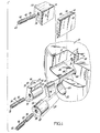
- a portion of a cutter body 10 is illustrated which is generally circular in configuration and adapted to be rotated about a central axis during a cutting operation.
- the cutter body is provided with a plurality of insert pockets, one of which is illustrated and is designated generally by the numeral 12.
- the insert pocket 12 is configured to receive an indexable cutting insert 14, which is secured therein by locking wedge 16.
- An insert 18 for adjusting the radial position of the insert is undercut portion functions to define leading and radial locating supports 78 and 80 for receiving insert 14.
- the front planar surface 46 of inserrt 14 is disposed in abutting relationship with the leading locating support 78 of the insert seat 18, while an edge face 50 of the insert is disposed in abutting relationship with the radial locating support or rail 80.
- the locating rail acts as a radially adjustable floor for the insert 14.
- the radial position of the radial locating support 80 will determine the radial position of the insert 14.
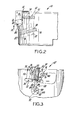
- the radial location of the insert seat 18 is adjusted by rotating differential screw 42, which in turn, regulates the radial position of the insert 14. Thereafter, locking wedge 16 is adjusted radially inwardly until the insert 14 is securely clamped between the wedge 16 and the insert seat 18, as illustrated in Figure 2.
- a new and improved adjustable axial locating wedge 20 is provided which will enable the accurate adjustment of the axial position of the insert 14. More specifically, a locating wedge 20 is provided and includes a generally cylindrical plug member 82 and an upstanding planar wedge member 84. The upper surface 85 of the wedge member 84 is rounded to accommodate various insert configurations. Further, the upper surface 85 of wedge member 84 is disposed at an angle relative to the lower surface thereof. The locating wedge 20 is intended to be received within the groove 22 formed in the rear wall 34 of the insert pocket such that the upper portion thereof is in abutting relationship with the axially lowermost cutting edge face 50 of the insert.
- the cylindrical plug member 82 is provided with a longitudinally extending slot 86 for receiving the lower edge of the wedge member 84.
- the wedge member 84 is interfit and secured within the groove 86 of plug member 82 by, for example, press fitting or tack welding.
- the plug member 82 and the wedge member 84 may be formed of a one piece unit or integrally investment cast.
- the connection between the members 82 and 84 must be rigid such that when the position of the plug 82 is varied, the position of the wedge member 84 will be similarly varied.
- Plug member 82 includes a threaded aperture 88 for receiving differential screw 90. Similar to the other differential screws 40 and 42, differential screw 90 is provided with a non-circular recess 92, as well as oppositely threaded radially inner and outer portions 94 and 96, respectively. The radially outer threaded portion 96 is received within the threaded aperture 88 of plug member 82, while the radial inner threaded portion 94 is received in a threaded aperture (not shown) disposed at the rear of receiving groove 22.
- Receiving groove 22 is configured to slidably receive adjustable locating wedge 20 and consists of a cylindrical portion 100, as well as a narrow channel portion 102 for guiding the planar wedge member 84. As illustrated in Figure 3, the channel portion 102 of receiving groove 22 is aligned with the insert 14 such that the upper rounded surface 85 of the wedge member 84 will be in. abutting relationship with the insert 14.
- the receiving groove 22, which extends radially inwardly from the periphery of the cutter body 10 is inclined upwardly relative to the rear wall 34 of the insert pocket, as more particularly illustrated in Figure 2.
- narrow channel 102 with the upstanding wedge member 84 prevents the unwanted rotation of plug member 82 during a cutting operation.
- the angle of inclination of the groove 22 will complement the configuration of the wedge member 84 to facilitate maximum contact between the locating wedge 20 and the insert 14.
- each 'insert 14 In use, it is desirable to accurately secure each 'insert 14 within each insert pocket 12 of the cutter body 10 to achieve a constant radial diameter and axial tracking.
- the subject invention facilitates the adjustment of the axial and radial position of each insert, thereby overcoming various problems such as insert run out. More specifically, to adjust the axial position of the insert 14, the location of the locating wedge 20 is adjusted within the receiving groove 22, by rotating differential screw 90. As illustrated in Figure 2, as the position of the locating wedge 20 is adjusted radially inwardly within groove 22, the upper edge 85 of the planar wedge member 84 is axially raised, in the direction of arrow A.
- the position of the locating wedge 20 is varied within the receiving groove 22 until the desired axial position of the insert is achieved.
- the axial position of the wedge member 84 is raised by adjusting the locating wedge 20 radially inwardly, the axial position of the insert will be correspondingly elevated.
- the radial position of the insert 14 can be regulated by adjusting the radial position of the insert seat 18 using differential screw 42.
- the insert 14 is locked securely in the insert pocket 12 by tightening the locking wedge 16 radially inwardly using differential screw 40 to achieve the configuration illustrated in Figure 3. This procedure is then repeated with each insert and insert pocket about the cutter body such that a constant outer diameter is defined and run out problems are avoided.
- the subject invention provides a new and improved adjustable locating wedge and insert assembly for an indexable cutting tool which facilitates the axial adjustment of an insert within the pocket of a cutter body.
- a milling cutter which is adapted to be rotated about a central axis includes at least one insert pocket having opposed leading and trailing walls, as well as a rear wall disposed perpendicular thereto.
- An indexable insert is received within the insert pocket and clamped therein by an adjustable locking wedge.
- an adjustable locating wedge is provided and is received in a groove located in the rear wall of the insert pocket. The groove is disposed at an angle relative to the rear wall such that as the position of the locating wedge within the groove is varied, the axial position of the wedge is varied.
- the groove is aligned with the lowermost cutting edge of the insert such that a portion of the locating wedge is in abutting relationship with the insert.
- the adjustment of the locating wedge within the groove varies the axial position of the insert to eliminate run out problems and to provide smooth machined cuts.
- an insert seat is provided for adjusting the radial position of the insert.
Applications Claiming Priority (2)
| Application Number | Priority Date | Filing Date | Title |
|---|---|---|---|
| US162426 | 1980-06-24 | ||
| US06/162,426 US4311418A (en) | 1980-06-24 | 1980-06-24 | Adjustable axial and radial locating wedge assemblies for an indexable insert cutting tool |
Publications (2)
| Publication Number | Publication Date |
|---|---|
| EP0042667A2 true EP0042667A2 (de) | 1981-12-30 |
| EP0042667A3 EP0042667A3 (de) | 1982-06-02 |
Family
ID=22585564
Family Applications (1)
| Application Number | Title | Priority Date | Filing Date |
|---|---|---|---|
| EP81302245A Ceased EP0042667A3 (de) | 1980-06-24 | 1981-05-20 | Axial und radial einstellbare Positionierkeilanordnung für einen indexierbaren Schneideinsatz eines Schneidwerkzeuges |
Country Status (7)
| Country | Link |
|---|---|
| US (1) | US4311418A (de) |
| EP (1) | EP0042667A3 (de) |
| JP (1) | JPS5741110A (de) |
| AU (1) | AU7106781A (de) |
| BR (1) | BR8104032A (de) |
| CA (1) | CA1160821A (de) |
| ZA (1) | ZA813153B (de) |
Cited By (4)
| Publication number | Priority date | Publication date | Assignee | Title |
|---|---|---|---|---|
| EP0182290A2 (de) * | 1984-11-15 | 1986-05-28 | Walter Kieninger GmbH Hartmetall- und Diamantwerkzeugfabrik | Messerkopf |
| EP0282090A1 (de) * | 1987-03-12 | 1988-09-14 | ENTWICKLUNGSZENTRUM FÜR ZERSPANUNGSTECHNIK GMBH & CO. KG | Messerkopf |
| EP0308901A1 (de) * | 1987-09-23 | 1989-03-29 | Gte Valenite Corporation | Träger für ein Schneidwerkzeug |
| EP3069809A4 (de) * | 2014-05-15 | 2017-06-21 | Tungaloy Corporation | Einsatzbefestigungsmechanismus, rotierendes schneidwerkzeug, werkzeugkörper, keilelement und regulierungselement |
Families Citing this family (16)
| Publication number | Priority date | Publication date | Assignee | Title |
|---|---|---|---|---|
| DE3220363C2 (de) * | 1982-05-29 | 1991-06-13 | Santrade Ltd., Luzern | Fräsmesserkopf für Schruppbearbeitung |
| SE454490B (sv) * | 1984-07-05 | 1988-05-09 | Seco Tools Ab | Fres med instellbar kassett |
| JPH0639005B2 (ja) * | 1985-11-01 | 1994-05-25 | 本田技研工業株式会社 | 切削用工具 |
| US6190096B1 (en) | 1996-08-07 | 2001-02-20 | Kennametal Inc. | Indexable cutting insert with indexing marks |
| US6877934B2 (en) * | 2002-10-28 | 2005-04-12 | Rem Sales, Inc. | Milling head for thread whirling |
| SE528820C2 (sv) * | 2004-12-14 | 2007-02-20 | Seco Tools Ab | Borrningsverktyg med justerbar kassett |
| DE102006024880A1 (de) * | 2006-05-24 | 2007-11-29 | Kennametal Widia Produktions Gmbh & Co. Kg | Werkzeug mit Einstellvorrichtung |
| IL177613A0 (en) * | 2006-08-21 | 2006-12-10 | Iscar Ltd | A cutting insert adjustment device |
| US7753626B2 (en) * | 2007-01-18 | 2010-07-13 | Kennametal Inc. | Micro-adjustable differential screw assembly |
| US8327742B1 (en) * | 2008-03-07 | 2012-12-11 | Lockheed Martin Corporation | Diamond tool micro-height-adjuster within a multi-tool rotating head |
| JP5338425B2 (ja) * | 2008-03-28 | 2013-11-13 | 三菱マテリアル株式会社 | インサート着脱式カッタ |
| DE202008006375U1 (de) * | 2008-05-08 | 2008-09-04 | Kennametal Inc. | Werkzeug zum Dreh-Dreh-Räumen oder Außenfräsen von Werkstücken |
| DE102012004654A1 (de) * | 2011-03-29 | 2012-10-04 | Kennametal India Limited | Schneideinheit, Verfahren zur Änderung des Spanwinkels der Schneideinheit und Verfahren zu ihrem Zusammenbau |
| US20150336177A1 (en) * | 2014-05-23 | 2015-11-26 | Honda Motor Co., Ltd. | Diamond tip cutting tool |
| US10144071B2 (en) * | 2017-03-16 | 2018-12-04 | Iscar, Ltd. | Tool holder having position adjustment arrangement and cutting tool |
| CN109434173A (zh) * | 2018-12-27 | 2019-03-08 | 安徽华菱汽车有限公司 | 一种铣刀及铣刀调节组件 |
Citations (7)
| Publication number | Priority date | Publication date | Assignee | Title |
|---|---|---|---|---|
| GB872693A (en) * | 1960-02-08 | 1961-07-12 | Thurston Vincent Williams | Improvements in or relating to indexing means for bits of cutting-tools |
| DE1175963B (de) * | 1958-10-25 | 1964-08-13 | Biax Werkzeuge G M B H Praez S | Praezisionsmesserkopf mit einstellbaren Schneiden |
| US3242553A (en) * | 1961-07-03 | 1966-03-29 | Saab Scania Ab | Cutter |
| US3588976A (en) * | 1968-09-18 | 1971-06-29 | Allegheny Ludlum Steel | Cutter with adjustable clamping blades |
| DD106284A1 (de) * | 1973-08-31 | 1974-06-12 | ||
| DD106792A1 (de) * | 1973-05-08 | 1974-07-05 | ||
| US3847555A (en) * | 1971-06-03 | 1974-11-12 | Lloyd Ltd Richard | Milling cutters |
Family Cites Families (8)
| Publication number | Priority date | Publication date | Assignee | Title |
|---|---|---|---|---|
| US3121939A (en) * | 1957-01-18 | 1964-02-25 | O K Tool Co Inc | Cutting tool with indexable bit |
| US3027624A (en) * | 1958-10-30 | 1962-04-03 | O K Tool Co Inc | Inserted bit-clamping means |
| US3217384A (en) * | 1962-02-26 | 1965-11-16 | Sandvikens Jernverks Ab | Milling cutter |
| US3188718A (en) * | 1962-04-10 | 1965-06-15 | Wetzel Internat | Precision milling cutter with inserted teeth |
| US3378901A (en) * | 1965-10-21 | 1968-04-23 | Goddard & Goddard Company | Milling cutter |
| GB1175885A (en) * | 1967-05-01 | 1970-01-01 | Murex Ltd | Improvements in or relating to Cutting Tools |
| US3739442A (en) * | 1971-12-27 | 1973-06-19 | N Lovendahl | Cutting tools |
| US3802043A (en) * | 1972-10-30 | 1974-04-09 | C Garih | Milling cutter with mechanically clamped teeth |
-
1980
- 1980-06-24 US US06/162,426 patent/US4311418A/en not_active Expired - Lifetime
-
1981
- 1981-05-12 ZA ZA00813153A patent/ZA813153B/xx unknown
- 1981-05-20 EP EP81302245A patent/EP0042667A3/de not_active Ceased
- 1981-05-27 AU AU71067/81A patent/AU7106781A/en not_active Abandoned
- 1981-06-19 CA CA000380266A patent/CA1160821A/en not_active Expired
- 1981-06-23 JP JP56096112A patent/JPS5741110A/ja active Pending
- 1981-06-24 BR BR8104032A patent/BR8104032A/pt unknown
Patent Citations (7)
| Publication number | Priority date | Publication date | Assignee | Title |
|---|---|---|---|---|
| DE1175963B (de) * | 1958-10-25 | 1964-08-13 | Biax Werkzeuge G M B H Praez S | Praezisionsmesserkopf mit einstellbaren Schneiden |
| GB872693A (en) * | 1960-02-08 | 1961-07-12 | Thurston Vincent Williams | Improvements in or relating to indexing means for bits of cutting-tools |
| US3242553A (en) * | 1961-07-03 | 1966-03-29 | Saab Scania Ab | Cutter |
| US3588976A (en) * | 1968-09-18 | 1971-06-29 | Allegheny Ludlum Steel | Cutter with adjustable clamping blades |
| US3847555A (en) * | 1971-06-03 | 1974-11-12 | Lloyd Ltd Richard | Milling cutters |
| DD106792A1 (de) * | 1973-05-08 | 1974-07-05 | ||
| DD106284A1 (de) * | 1973-08-31 | 1974-06-12 |
Cited By (6)
| Publication number | Priority date | Publication date | Assignee | Title |
|---|---|---|---|---|
| EP0182290A2 (de) * | 1984-11-15 | 1986-05-28 | Walter Kieninger GmbH Hartmetall- und Diamantwerkzeugfabrik | Messerkopf |
| EP0182290A3 (de) * | 1984-11-15 | 1988-04-20 | Walter Kieninger GmbH Hartmetall- und Diamantwerkzeugfabrik | Messerkopf |
| EP0282090A1 (de) * | 1987-03-12 | 1988-09-14 | ENTWICKLUNGSZENTRUM FÜR ZERSPANUNGSTECHNIK GMBH & CO. KG | Messerkopf |
| US4848977A (en) * | 1987-03-12 | 1989-07-18 | Entwicklungszentrum Fur Zerspanungstechnik | Cutter head |
| EP0308901A1 (de) * | 1987-09-23 | 1989-03-29 | Gte Valenite Corporation | Träger für ein Schneidwerkzeug |
| EP3069809A4 (de) * | 2014-05-15 | 2017-06-21 | Tungaloy Corporation | Einsatzbefestigungsmechanismus, rotierendes schneidwerkzeug, werkzeugkörper, keilelement und regulierungselement |
Also Published As
| Publication number | Publication date |
|---|---|
| US4311418A (en) | 1982-01-19 |
| ZA813153B (en) | 1982-08-25 |
| JPS5741110A (en) | 1982-03-08 |
| BR8104032A (pt) | 1982-03-16 |
| CA1160821A (en) | 1984-01-24 |
| AU7106781A (en) | 1982-01-07 |
| EP0042667A3 (de) | 1982-06-02 |
Similar Documents
| Publication | Publication Date | Title |
|---|---|---|
| US4311418A (en) | Adjustable axial and radial locating wedge assemblies for an indexable insert cutting tool | |
| US4318647A (en) | Adjustable insert seat and wedge assembly for an indexable boring cutter | |
| US5704736A (en) | Dove-tail end mill having replaceable cutter inserts | |
| US3708843A (en) | Holder for indexable cutting insert | |
| US3785417A (en) | Cutterhead with replaceable inserts | |
| US6702526B2 (en) | Cutting tool | |
| US6030153A (en) | Milling tool with axial adjustment | |
| EP0069316B2 (de) | Fräser mit einstellbarem Schlichteinsatz | |
| US3662444A (en) | Indexable cutting insert and holder therefor | |
| EP0035848B1 (de) | Zur Endbearbeitung vorgesehener indexierbarer Schneideinsatz | |
| EP0912285B1 (de) | Schneidwerkzeug für verzahnte gegenstände | |
| US4332513A (en) | Face grooving tool | |
| JP3495105B2 (ja) | フライスカッタ本体 | |
| MXPA03001961A (es) | Fresa capaz de utilizar insertos de diversas formas geometricas. | |
| US20040223819A1 (en) | Insert retention screw and tool body and insert therewith | |
| US4060881A (en) | Cutter head assembly for gear cutting machines | |
| US4995767A (en) | Face milling cutter with indexable inserts | |
| US4936718A (en) | Rotary cutter and associated method | |
| EP0584075A1 (de) | Feinregelmechanismus für einen werkzeughalter. | |
| US8192112B2 (en) | Universal rotary cutter head with back clamping system and constant cutting dimensions and constant weight regridable inserts | |
| JPH0761563B2 (ja) | フライス | |
| EP1499479B1 (de) | Schneidwerkzeug | |
| US4744703A (en) | Rotary cutter for slotting or cut-off | |
| EP0037692A2 (de) | Einstellbares Spannkeilsystem für einen Schneideinsatz eines Fräsers | |
| US3509612A (en) | Milling cutter and blade assembly |
Legal Events
| Date | Code | Title | Description |
|---|---|---|---|
| PUAI | Public reference made under article 153(3) epc to a published international application that has entered the european phase |
Free format text: ORIGINAL CODE: 0009012 |
|
| AK | Designated contracting states |
Designated state(s): AT BE CH DE FR GB IT LI NL SE |
|
| PUAL | Search report despatched |
Free format text: ORIGINAL CODE: 0009013 |
|
| AK | Designated contracting states |
Designated state(s): AT BE CH DE FR GB IT LI NL SE |
|
| 17P | Request for examination filed |
Effective date: 19820601 |
|
| STAA | Information on the status of an ep patent application or granted ep patent |
Free format text: STATUS: THE APPLICATION HAS BEEN REFUSED |
|
| 18R | Application refused |
Effective date: 19850715 |
|
| RIN1 | Information on inventor provided before grant (corrected) |
Inventor name: ERKFRITZ, DONALD SPENCER Inventor name: ALPHONSI, LAWRENCE ANTHONY |