EP0042324B1 - Dispositif d'observation binoculaire notamment pour une lunette - Google Patents
Dispositif d'observation binoculaire notamment pour une lunette Download PDFInfo
- Publication number
- EP0042324B1 EP0042324B1 EP81400900A EP81400900A EP0042324B1 EP 0042324 B1 EP0042324 B1 EP 0042324B1 EP 81400900 A EP81400900 A EP 81400900A EP 81400900 A EP81400900 A EP 81400900A EP 0042324 B1 EP0042324 B1 EP 0042324B1
- Authority
- EP
- European Patent Office
- Prior art keywords
- eyepiece
- axis
- optical axis
- converging
- centered
- Prior art date
- Legal status (The legal status is an assumption and is not a legal conclusion. Google has not performed a legal analysis and makes no representation as to the accuracy of the status listed.)
- Expired
Links
- 230000003287 optical effect Effects 0.000 claims abstract description 32
- 210000000887 face Anatomy 0.000 description 6
- 239000011521 glass Substances 0.000 description 4
- 230000004075 alteration Effects 0.000 description 2
- 238000006073 displacement reaction Methods 0.000 description 2
- 210000001747 pupil Anatomy 0.000 description 2
- 230000000422 nocturnal effect Effects 0.000 description 1
Images
Classifications
-
- G—PHYSICS
- G02—OPTICS
- G02B—OPTICAL ELEMENTS, SYSTEMS OR APPARATUS
- G02B27/00—Optical systems or apparatus not provided for by any of the groups G02B1/00 - G02B26/00, G02B30/00
- G02B27/10—Beam splitting or combining systems
- G02B27/14—Beam splitting or combining systems operating by reflection only
- G02B27/144—Beam splitting or combining systems operating by reflection only using partially transparent surfaces without spectral selectivity
-
- G—PHYSICS
- G02—OPTICS
- G02B—OPTICAL ELEMENTS, SYSTEMS OR APPARATUS
- G02B23/00—Telescopes, e.g. binoculars; Periscopes; Instruments for viewing the inside of hollow bodies; Viewfinders; Optical aiming or sighting devices
- G02B23/12—Telescopes, e.g. binoculars; Periscopes; Instruments for viewing the inside of hollow bodies; Viewfinders; Optical aiming or sighting devices with means for image conversion or intensification
-
- G—PHYSICS
- G02—OPTICS
- G02B—OPTICAL ELEMENTS, SYSTEMS OR APPARATUS
- G02B23/00—Telescopes, e.g. binoculars; Periscopes; Instruments for viewing the inside of hollow bodies; Viewfinders; Optical aiming or sighting devices
- G02B23/16—Housings; Caps; Mountings; Supports, e.g. with counterweight
- G02B23/18—Housings; Caps; Mountings; Supports, e.g. with counterweight for binocular arrangements
Definitions
- the present invention relates to a binocular observation device for a single image and to the application of this device to a telescope with a single objective intended for day or night observation.
- Binoculars such as those mounted for example on microscopes usually include two rhomboidal prisms giving two beams spaced apart from the interpupillary distance and observed by the eyepieces. This system is well suited for observing an aerial image that forms in the glasses of rhomboid prisms. This system is not satisfactory when we want to observe with a short eyepiece focal length an actual image.
- binocular observation systems comprising only one optical system giving two beams at the interpupillary distance which can be observed directly.
- These binocular systems have limits because they do not allow short focal lengths without the observation being difficult. Furthermore, the correction of aberrations is difficult.
- the present invention relates to a binocular device for observing a single real or aerial image with a short focal length. Therefore the size is reduced.
- This device allows the adjustment of the eye gap and the adjustment of the focus. It can be associated with a telescope with a single objective in particular with a telescope for night observation so as to constitute a light and portable instrument and at low cost price.
- the device which makes it possible to observe a real or aerial image centered on an optical axis is essentially characterized by the fact that it comprises an optical element provided with a semi-reflecting surface allowing the light coming from the image to pass through an eyepiece converge and deflect the other part of light onto a converging group of lenses having substantially the same focal distance as that of the eyepiece and centered on a frontal optical axis, oblique to the optical axis of said eyepiece, this group of lenses being followed by a reflector behind which the reflected optical axis is offset by the interpupillary distance with respect to this axis of said eyepiece, the focal points of the eyepiece and of the group of lenses being substantially combined.
- the eyepiece is arranged so that its axis is coaxial with the axis on which the image is centered and that it is separated by an air gap from the optical element.
- the reflector is composed of a prism, a blade with parallel faces attached to the front face of this prism and a blade with parallel faces attached to the rear face of this prism.
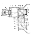
- the single figure is an axial section of a binocular device according to the invention.
- the binocular device which is represented by the figure is used for examining a real image 72. It is mounted in a housing 2 and it includes two eyepieces which give two beams centered on two parallel axes 12 and 14 separated from the interpupillary distance .
- the light beam coming from the observed image 72 is centered on an axis 11 called the main one.
- the liminous beam coming from the image is received by a semi-reflecting optical element 3 which lets the beam pass along the optical axis 12 and which deflects the beam along the oblique frontal optical axis 13.
- This optical element is provided with a semi-reflecting surface 31 which lets the light pass along the axis 12 coaxial to 11. This surface 31 is positioned at 45 ° from the optical axis 11, the reflected axis 13 being perpendicular to 11 and 12.
- the element 3 is composed for example of two isosceles rectangular prisms 32 and 33 mounted so as to constitute a cube, the semi-reflecting surface 31 of which passes through two parallel edges. Part of the light passes through the semi-reflecting optical element 3 to go towards the eyepiece 4. Another part of the light is reflected along the front optical axis 13.
- the converging eyepiece 4 centered on the axis 12 is mounted behind the element 3, being separated by an air space from the prism 33.
- This eyepiece is, in the embodiment shown, formed by a doublet comprising towards the before a converging lens 41 and towards the rear a diverging lens 42, the two lenses being joined to one another.
- the directing eye observes directly behind this eyepiece 4.
- the second eyepiece includes a group or converging lens system 5 centered on the front axis 13 and a reflector 6 used to translate the image given by the lens system and to reflect light beam from the front axis 13 to the axis 14.
- the group of lenses 5 is composed for example towards the front of a converging doublet 51 separated by an air gap from the prism 32 and towards the rear of a converging doublet 52.
- Each doublet is composed towards the 'before a diverging lens 511 or 521 and rearwardly of a converging lens 512 or 522, the two lenses being joined to one another. This structure with two doublets favors the correction of aberrations.
- the focal points of the eyepiece 4 and the lens system are combined.
- the diameter of the lenses of the system is greater than the diameter of the lenses of the doublet 4.
- the reflector 6 is disposed behind the lens system 5 from which it is separated by an inter air valley.
- This reflector which constitutes a continuous crossing of glass, brings the exit pupil of the system 5 closer by a reflection on the reflecting surface 621 reflects the optical axis from 13 to 14.
- This reflector preferably has zero power. It comprises at the inlet a plane diopter 611 perpendicular to 13 and at the outlet a plane diopter 631 perpendicular to 14.
- the reflecting surface 621 is inclined at 45 ° relative to the front axis 43. It is parallel to the semi surface -reflective 31 so that the main optical axis incident 11 on the surface 31 and the bent optical axis 14 are parallel and offset laterally.
- This reflector 6 breaks down for example into a blade with parallel faces 61 centered on the front axis 13, into a reflective prism 62 and into a blade with parallel faces 63 centered on the lateral optical axis 14.
- the prism 62 is a prism isosceles rectangle with total reflection.
- the blade with parallel faces 61 which is positioned perpendicular to the axis 13, between the prism 62 and the converging group of lenses 5 is attached to the front face of the prism 62 and is separated by an air gap from the lens group 5.
- the blade with parallel faces 63 which is positioned perpendicular to the axis 14 is attached to the rear face of the prism 62.
- the passage of glass in the assembly 6 brings a translation of the pupil towards the system 5 and a field more tall.
- the planar diopter 631 is substantially located at the same distance from the axis 13 as the rear diopter 421 of the lens 42 of the eyepiece 4.
- the adjustment of the eye gap can be effected by relative displacement along the axis 13 of the reflector 5-6.
- the focusing is carried out by the eyepiece 4 and by relative displacement of the device with respect to the image.
- the binocular device described above is used to observe a real image.
- this binocular device can be associated with a telescope provided with a luminance intensification tube as shown in the appended figure. It then makes it possible to observe the image formed on the output 72 of the luminance intensification tube 7 which is at the focus of the eyepiece 4 and of the lens system 5.
- This tube 7 is mounted at the rear of a lens 8 which is centered on the main optical axis 11 coaxial with the axis 12 of the eyepiece 4.
- the image supplied by the objective 8 is received at the entrance of the luminance intensification tube.
- the reflector 6 could be made in one piece.
Landscapes
- Physics & Mathematics (AREA)
- General Physics & Mathematics (AREA)
- Optics & Photonics (AREA)
- Astronomy & Astrophysics (AREA)
- Spectroscopy & Molecular Physics (AREA)
- Telescopes (AREA)
- Microscoopes, Condenser (AREA)
- Length Measuring Devices By Optical Means (AREA)
- Medicines Containing Antibodies Or Antigens For Use As Internal Diagnostic Agents (AREA)
- Geophysics And Detection Of Objects (AREA)
- Measuring Pulse, Heart Rate, Blood Pressure Or Blood Flow (AREA)
- Investigating Or Analysing Materials By Optical Means (AREA)
- Materials For Medical Uses (AREA)
- Organic Low-Molecular-Weight Compounds And Preparation Thereof (AREA)
Priority Applications (1)
| Application Number | Priority Date | Filing Date | Title |
|---|---|---|---|
| AT81400900T ATE8937T1 (de) | 1980-06-12 | 1981-06-05 | Vorrichtung zur binokularen beobachtung insbesondere fuer ein fernglas. |
Applications Claiming Priority (2)
| Application Number | Priority Date | Filing Date | Title |
|---|---|---|---|
| FR8013085 | 1980-06-12 | ||
| FR8013085A FR2484658A1 (fr) | 1980-06-12 | 1980-06-12 | Lunette binoculaire |
Publications (2)
| Publication Number | Publication Date |
|---|---|
| EP0042324A1 EP0042324A1 (fr) | 1981-12-23 |
| EP0042324B1 true EP0042324B1 (fr) | 1984-08-08 |
Family
ID=9243020
Family Applications (1)
| Application Number | Title | Priority Date | Filing Date |
|---|---|---|---|
| EP81400900A Expired EP0042324B1 (fr) | 1980-06-12 | 1981-06-05 | Dispositif d'observation binoculaire notamment pour une lunette |
Country Status (10)
| Country | Link |
|---|---|
| US (1) | US4568153A (show.php) |
| EP (1) | EP0042324B1 (show.php) |
| AT (1) | ATE8937T1 (show.php) |
| CA (1) | CA1166049A (show.php) |
| DE (1) | DE3165386D1 (show.php) |
| ES (1) | ES502958A0 (show.php) |
| FR (1) | FR2484658A1 (show.php) |
| IL (1) | IL62982A (show.php) |
| NO (1) | NO163796C (show.php) |
| YU (1) | YU41247B (show.php) |
Families Citing this family (5)
| Publication number | Priority date | Publication date | Assignee | Title |
|---|---|---|---|---|
| FR2718534B1 (fr) * | 1994-04-12 | 1996-06-28 | Sopelem Sofretec | Lunette de vision binoculaire et son procédé de montage. |
| JPH08299275A (ja) * | 1995-05-15 | 1996-11-19 | Nippon Koden Corp | 両眼撮像用光学装置および両眼撮像装置 |
| SE507815C2 (sv) * | 1996-10-24 | 1998-07-20 | Simrad Optronics Asa | Binokulär bildförstärkarkikare |
| CN1280651C (zh) * | 2004-09-17 | 2006-10-18 | 陇涤湘 | 一种单筒双目观察望远镜 |
| FR2916863B1 (fr) * | 2007-05-29 | 2009-08-14 | Sagem Defense Securite | Jumelle bioculaire de vision nocturne |
Family Cites Families (9)
| Publication number | Priority date | Publication date | Assignee | Title |
|---|---|---|---|---|
| DE596913C (de) * | 1932-12-20 | 1934-05-12 | Zeiss Carl Fa | Strahlenteilungssystem fuer binokulare Mikroskope |
| FR922184A (fr) * | 1945-12-19 | 1947-06-02 | Sadir Carpentier | Masque binoculaire |
| FR1154521A (fr) * | 1956-06-15 | 1958-04-11 | Loupe binoculaire | |
| GB928215A (en) * | 1960-11-22 | 1963-06-12 | Optische Ind De Oude Delft Nv | Improvements relating to optical viewing devices including electron image amplifiers |
| NL6503866A (show.php) * | 1965-03-26 | 1966-09-27 | ||
| DE1217099B (de) * | 1965-08-07 | 1966-05-18 | Zeiss Carl Fa | Stereomikroskopische Einrichtung fuer zwei und mehr Beobachter |
| FR2123564A5 (show.php) * | 1969-12-10 | 1972-09-15 | Trt Telecom Radio Electr | |
| GB2021803B (en) * | 1978-05-24 | 1982-06-09 | Pilkington Perkin Elmer Ltd | Optical apparatus |
| DE2948687C2 (de) * | 1979-12-04 | 1987-04-23 | Philips Patentverwaltung Gmbh, 2000 Hamburg | Binokulare Betrachtungsanordnung |
-
1980
- 1980-06-12 FR FR8013085A patent/FR2484658A1/fr active Granted
-
1981
- 1981-05-28 IL IL62982A patent/IL62982A/xx not_active IP Right Cessation
- 1981-06-05 AT AT81400900T patent/ATE8937T1/de not_active IP Right Cessation
- 1981-06-05 EP EP81400900A patent/EP0042324B1/fr not_active Expired
- 1981-06-05 DE DE8181400900T patent/DE3165386D1/de not_active Expired
- 1981-06-09 YU YU1448/81A patent/YU41247B/xx unknown
- 1981-06-10 NO NO811964A patent/NO163796C/no unknown
- 1981-06-11 ES ES502958A patent/ES502958A0/es active Granted
- 1981-06-11 CA CA000379580A patent/CA1166049A/fr not_active Expired
-
1983
- 1983-08-01 US US06/518,325 patent/US4568153A/en not_active Expired - Fee Related
Also Published As
| Publication number | Publication date |
|---|---|
| ES8204179A1 (es) | 1982-04-01 |
| CA1166049A (fr) | 1984-04-24 |
| NO163796C (no) | 1990-07-18 |
| DE3165386D1 (en) | 1984-09-13 |
| EP0042324A1 (fr) | 1981-12-23 |
| FR2484658B1 (show.php) | 1984-08-24 |
| FR2484658A1 (fr) | 1981-12-18 |
| YU144881A (en) | 1983-10-31 |
| NO811964L (no) | 1981-12-14 |
| ES502958A0 (es) | 1982-04-01 |
| US4568153A (en) | 1986-02-04 |
| ATE8937T1 (de) | 1984-08-15 |
| NO163796B (no) | 1990-04-09 |
| IL62982A (en) | 1986-08-31 |
| YU41247B (en) | 1986-12-31 |
Similar Documents
| Publication | Publication Date | Title |
|---|---|---|
| EP0011024B1 (fr) | Système de visualisation monté sur un casque | |
| EP0162493B1 (fr) | Lunette à deux grossissements | |
| FR2461966A1 (fr) | Accouplement demontable permettant le couplage d'une paire de fibres photoconductrices | |
| FR2695214A1 (fr) | Diviseur de puissance optique pour diviser une puissance lumineuse élevée et procédé correspondant. | |
| EP0233214A1 (en) | BINOCULAR INSTRUMENT WITH IMAGE INTENSIFIER. | |
| EP0042324B1 (fr) | Dispositif d'observation binoculaire notamment pour une lunette | |
| US4214371A (en) | Device for illuminating reticles in optical instruments | |
| EP0025398B1 (fr) | Système optique à plusieurs champs | |
| US20200192075A1 (en) | Illuminated reticle system with fresnel lens | |
| EP0546887B1 (fr) | Dispositif pour déterminer la portion d'un champ regardée par l'oeil d'un observateur | |
| EP1998208B1 (fr) | Jumelle bioculaire de vision nocturne | |
| EP0475797B1 (fr) | Système optique large champ et grande ouverture, notamment destiné à une voie de nuit pour épiscope, et épiscope équipé d'un tel système optique | |
| EP0004813B1 (fr) | Instrument optique d'observation | |
| WO2001067153A2 (fr) | Relais optique correcteur d'aberrations pour systeme optique, notamment telescope a miroirs | |
| EP0005705A1 (fr) | Lunette optique et son application à la réalisation de jumelles | |
| EP0128815A2 (fr) | Dispositif d'observation optique à deux champs | |
| EP0678276B1 (fr) | Dispositif de visée à suivi du regard | |
| FR2472762A1 (fr) | Dispositif de vision binoculaire de jour | |
| EP1445636A1 (fr) | Télescope optique grand champ, en particulier pour l'observation astronomique à partir d'un satellite | |
| FR2838528A3 (fr) | Objectif de prises de vues a champ de 180 degres et de structure simplifiee | |
| EP4409346A1 (fr) | Microscope optique comprenant un dispositif opto-mécanique de réglage fin et procédé d'ajustement opto-mécanique | |
| JPH0330115B2 (show.php) | ||
| FR2655741A1 (fr) | Systeme optique d'observation multidirectionnelle autorisant la selection d'une direction. | |
| EP0119116A1 (fr) | Dispositif de transmission de signaux lumineux entre des fibres optiques | |
| WO2002033438A1 (fr) | Dispositif a surface equivalente laser parfaitement connue et procede associe |
Legal Events
| Date | Code | Title | Description |
|---|---|---|---|
| PUAI | Public reference made under article 153(3) epc to a published international application that has entered the european phase |
Free format text: ORIGINAL CODE: 0009012 |
|
| AK | Designated contracting states |
Designated state(s): AT BE CH DE GB IT LU NL SE |
|
| 17P | Request for examination filed |
Effective date: 19811028 |
|
| ITF | It: translation for a ep patent filed | ||
| GRAA | (expected) grant |
Free format text: ORIGINAL CODE: 0009210 |
|
| AK | Designated contracting states |
Designated state(s): AT BE CH DE GB IT LI LU NL SE |
|
| REF | Corresponds to: |
Ref document number: 8937 Country of ref document: AT Date of ref document: 19840815 Kind code of ref document: T |
|
| REF | Corresponds to: |
Ref document number: 3165386 Country of ref document: DE Date of ref document: 19840913 |
|
| PLBE | No opposition filed within time limit |
Free format text: ORIGINAL CODE: 0009261 |
|
| STAA | Information on the status of an ep patent application or granted ep patent |
Free format text: STATUS: NO OPPOSITION FILED WITHIN TIME LIMIT |
|
| 26N | No opposition filed | ||
| ITTA | It: last paid annual fee | ||
| EPTA | Lu: last paid annual fee | ||
| EAL | Se: european patent in force in sweden |
Ref document number: 81400900.7 |
|
| PGFP | Annual fee paid to national office [announced via postgrant information from national office to epo] |
Ref country code: AT Payment date: 19960523 Year of fee payment: 16 |
|
| PGFP | Annual fee paid to national office [announced via postgrant information from national office to epo] |
Ref country code: SE Payment date: 19960528 Year of fee payment: 16 Ref country code: GB Payment date: 19960528 Year of fee payment: 16 |
|
| PGFP | Annual fee paid to national office [announced via postgrant information from national office to epo] |
Ref country code: DE Payment date: 19960612 Year of fee payment: 16 |
|
| PGFP | Annual fee paid to national office [announced via postgrant information from national office to epo] |
Ref country code: NL Payment date: 19960630 Year of fee payment: 16 |
|
| PGFP | Annual fee paid to national office [announced via postgrant information from national office to epo] |
Ref country code: LU Payment date: 19960701 Year of fee payment: 16 |
|
| PGFP | Annual fee paid to national office [announced via postgrant information from national office to epo] |
Ref country code: CH Payment date: 19960704 Year of fee payment: 16 |
|
| PGFP | Annual fee paid to national office [announced via postgrant information from national office to epo] |
Ref country code: BE Payment date: 19960731 Year of fee payment: 16 |
|
| PG25 | Lapsed in a contracting state [announced via postgrant information from national office to epo] |
Ref country code: LU Free format text: LAPSE BECAUSE OF NON-PAYMENT OF DUE FEES Effective date: 19970605 Ref country code: GB Free format text: LAPSE BECAUSE OF NON-PAYMENT OF DUE FEES Effective date: 19970605 Ref country code: AT Effective date: 19970605 |
|
| PG25 | Lapsed in a contracting state [announced via postgrant information from national office to epo] |
Ref country code: SE Effective date: 19970606 |
|
| PG25 | Lapsed in a contracting state [announced via postgrant information from national office to epo] |
Ref country code: LI Free format text: LAPSE BECAUSE OF NON-PAYMENT OF DUE FEES Effective date: 19970630 Ref country code: CH Free format text: LAPSE BECAUSE OF NON-PAYMENT OF DUE FEES Effective date: 19970630 Ref country code: BE Effective date: 19970630 |
|
| BERE | Be: lapsed |
Owner name: SOC. D'OPTIQUE PRECISION ELECTRONIQUE ET MECANIQUE Effective date: 19970630 |
|
| PG25 | Lapsed in a contracting state [announced via postgrant information from national office to epo] |
Ref country code: NL Effective date: 19980101 |
|
| GBPC | Gb: european patent ceased through non-payment of renewal fee |
Effective date: 19970605 |
|
| REG | Reference to a national code |
Ref country code: CH Ref legal event code: PL |
|
| EUG | Se: european patent has lapsed |
Ref document number: 81400900.7 |
|
| NLV4 | Nl: lapsed or anulled due to non-payment of the annual fee |
Effective date: 19980101 |
|
| PG25 | Lapsed in a contracting state [announced via postgrant information from national office to epo] |
Ref country code: DE Free format text: LAPSE BECAUSE OF NON-PAYMENT OF DUE FEES Effective date: 19980303 |