EP0042160A2 - Method and means for storing and bringing heat to a higher temperature - Google Patents
Method and means for storing and bringing heat to a higher temperature Download PDFInfo
- Publication number
- EP0042160A2 EP0042160A2 EP81104555A EP81104555A EP0042160A2 EP 0042160 A2 EP0042160 A2 EP 0042160A2 EP 81104555 A EP81104555 A EP 81104555A EP 81104555 A EP81104555 A EP 81104555A EP 0042160 A2 EP0042160 A2 EP 0042160A2
- Authority
- EP
- European Patent Office
- Prior art keywords
- heat
- evaporator
- expeller
- temperature
- working medium
- Prior art date
- Legal status (The legal status is an assumption and is not a legal conclusion. Google has not performed a legal analysis and makes no representation as to the accuracy of the status listed.)
- Granted
Links
Images


Classifications
-
- F—MECHANICAL ENGINEERING; LIGHTING; HEATING; WEAPONS; BLASTING
- F24—HEATING; RANGES; VENTILATING
- F24D—DOMESTIC- OR SPACE-HEATING SYSTEMS, e.g. CENTRAL HEATING SYSTEMS; DOMESTIC HOT-WATER SUPPLY SYSTEMS; ELEMENTS OR COMPONENTS THEREFOR
- F24D11/00—Central heating systems using heat accumulated in storage masses
- F24D11/02—Central heating systems using heat accumulated in storage masses using heat pumps
-
- F—MECHANICAL ENGINEERING; LIGHTING; HEATING; WEAPONS; BLASTING
- F01—MACHINES OR ENGINES IN GENERAL; ENGINE PLANTS IN GENERAL; STEAM ENGINES
- F01K—STEAM ENGINE PLANTS; STEAM ACCUMULATORS; ENGINE PLANTS NOT OTHERWISE PROVIDED FOR; ENGINES USING SPECIAL WORKING FLUIDS OR CYCLES
- F01K17/00—Using steam or condensate extracted or exhausted from steam engine plant
- F01K17/02—Using steam or condensate extracted or exhausted from steam engine plant for heating purposes, e.g. industrial, domestic
-
- F—MECHANICAL ENGINEERING; LIGHTING; HEATING; WEAPONS; BLASTING
- F25—REFRIGERATION OR COOLING; COMBINED HEATING AND REFRIGERATION SYSTEMS; HEAT PUMP SYSTEMS; MANUFACTURE OR STORAGE OF ICE; LIQUEFACTION SOLIDIFICATION OF GASES
- F25B—REFRIGERATION MACHINES, PLANTS OR SYSTEMS; COMBINED HEATING AND REFRIGERATION SYSTEMS; HEAT PUMP SYSTEMS
- F25B17/00—Sorption machines, plants or systems, operating intermittently, e.g. absorption or adsorption type
- F25B17/08—Sorption machines, plants or systems, operating intermittently, e.g. absorption or adsorption type the absorbent or adsorbent being a solid, e.g. salt
-
- F—MECHANICAL ENGINEERING; LIGHTING; HEATING; WEAPONS; BLASTING
- F28—HEAT EXCHANGE IN GENERAL
- F28D—HEAT-EXCHANGE APPARATUS, NOT PROVIDED FOR IN ANOTHER SUBCLASS, IN WHICH THE HEAT-EXCHANGE MEDIA DO NOT COME INTO DIRECT CONTACT
- F28D20/00—Heat storage plants or apparatus in general; Regenerative heat-exchange apparatus not covered by groups F28D17/00 or F28D19/00
- F28D20/003—Heat storage plants or apparatus in general; Regenerative heat-exchange apparatus not covered by groups F28D17/00 or F28D19/00 using thermochemical reactions
-
- Y—GENERAL TAGGING OF NEW TECHNOLOGICAL DEVELOPMENTS; GENERAL TAGGING OF CROSS-SECTIONAL TECHNOLOGIES SPANNING OVER SEVERAL SECTIONS OF THE IPC; TECHNICAL SUBJECTS COVERED BY FORMER USPC CROSS-REFERENCE ART COLLECTIONS [XRACs] AND DIGESTS
- Y02—TECHNOLOGIES OR APPLICATIONS FOR MITIGATION OR ADAPTATION AGAINST CLIMATE CHANGE
- Y02B—CLIMATE CHANGE MITIGATION TECHNOLOGIES RELATED TO BUILDINGS, e.g. HOUSING, HOUSE APPLIANCES OR RELATED END-USER APPLICATIONS
- Y02B30/00—Energy efficient heating, ventilation or air conditioning [HVAC]
- Y02B30/62—Absorption based systems
- Y02B30/625—Absorption based systems combined with heat or power generation [CHP], e.g. trigeneration
-
- Y—GENERAL TAGGING OF NEW TECHNOLOGICAL DEVELOPMENTS; GENERAL TAGGING OF CROSS-SECTIONAL TECHNOLOGIES SPANNING OVER SEVERAL SECTIONS OF THE IPC; TECHNICAL SUBJECTS COVERED BY FORMER USPC CROSS-REFERENCE ART COLLECTIONS [XRACs] AND DIGESTS
- Y02—TECHNOLOGIES OR APPLICATIONS FOR MITIGATION OR ADAPTATION AGAINST CLIMATE CHANGE
- Y02E—REDUCTION OF GREENHOUSE GAS [GHG] EMISSIONS, RELATED TO ENERGY GENERATION, TRANSMISSION OR DISTRIBUTION
- Y02E20/00—Combustion technologies with mitigation potential
- Y02E20/14—Combined heat and power generation [CHP]
-
- Y—GENERAL TAGGING OF NEW TECHNOLOGICAL DEVELOPMENTS; GENERAL TAGGING OF CROSS-SECTIONAL TECHNOLOGIES SPANNING OVER SEVERAL SECTIONS OF THE IPC; TECHNICAL SUBJECTS COVERED BY FORMER USPC CROSS-REFERENCE ART COLLECTIONS [XRACs] AND DIGESTS
- Y02—TECHNOLOGIES OR APPLICATIONS FOR MITIGATION OR ADAPTATION AGAINST CLIMATE CHANGE
- Y02E—REDUCTION OF GREENHOUSE GAS [GHG] EMISSIONS, RELATED TO ENERGY GENERATION, TRANSMISSION OR DISTRIBUTION
- Y02E60/00—Enabling technologies; Technologies with a potential or indirect contribution to GHG emissions mitigation
- Y02E60/14—Thermal energy storage
Definitions
- the present invention relates to a method for storing and transforming up the temperature of heat, in which a working fluid is expelled from an absorbent by heat of a predetermined medium temperature range, the working fluid vapor which is produced during the expulsion is condensed at a relatively low temperature, and the condensed working fluid in the medium temperature range evaporates and is absorbed at elevated pressure to generate absorption heat of a relatively high temperature in the absorbent.
- the invention further relates to devices for carrying out such a method.
- heat transformer For facilities with operating or input heat with temperatures in a medium temperature range are fed and, on the one hand, supply useful or output heat at a higher temperature level and waste heat at a lower temperature level, the term "heat transformer" has become established. This term should also be used here in the sense given.
- the heat transformer according to DE-A-25 54 937 is intended to raise the waste heat of a power plant to a higher temperature level.
- NH 3 is used as the working medium.
- the heat transformer known from DE-A-26 35 557 works with the working material system NH 3 / H 2 0 / propane.
- Heat transformers operating intermittently are also known, e.g. from DE-A-26 29 441, 27 58 727 and 28 08 464.
- the heat transformer known from DE-A-26 29 441 is intended to generate force, with large amounts of ammonia having to be stored.
- DE-A-27 58 727 specifies a heat transformer operated as a multi-stage store, but without specifying how the operation is to be carried out.
- Na 2 S serves as the storage medium, which is dangerous and does not allow temperatures above 80 ° C.
- Methylamine should be used as the working medium, which is not only toxic, but also easily decomposes.
- CaCl 2 and LiC1 are provided as storage or absorption media. The specified facilities are very complicated and require many heat exchangers, which affects the efficiency.
- Metal hydrides could also be used as the working material system.
- the metal / hydrogen working substance system can only be used with a heat transformer that works according to the absorber principle, which is associated with considerable technical outlay.
- hydrogen gas there is always a certain risk of explosion, and the swelling of the hydrides during the hydrogen uptake poses problems that are difficult to solve technically.
- Heat transformers are needed for many purposes: heat supply and power generation are often coupled with each other, for example in thermal power stations, in diesel and gas engines that drive generators or compressor heat pumps and their. Waste heat is used in the process heat supply, for example in the chemical and food industries. On the one hand, effective heat storage is required because of the very differently structured heat and power requirements. On the other hand, the temperature level of the available heat often has to be increased in order to be able to use this heat. For example, thermal power plants are generally operated with optimal efficiency in terms of electricity generation, which means that the waste heat should be generated at the lowest possible temperature level. In contrast, the supply temperature of the heat transfer medium must be certain for the district heating supply must have increasing minimum value with increasing district heating demand.
- a storage system that supplies heat at a level that is higher than the load level during peak loads of the district heating network (e.g. load at night with 100 ° C and heat output during peak load periods with 130 ° C to 150 ° C) would result in a significant improvement in the overall efficiency of the Thermal power plant and district heating supply.
- heat is generated in the cooling circuit of the drive machine at 80 ° C to 100 ° C. This temperature level is too low for a district heating network or for process heat, since flow temperatures between 120 and 150 ° C are often required here.
- a store is required that not only provides compensation for fluctuating demand, but also can deliver the heat at a higher temperature level than it has been stored.
- Waste heat is often generated in industry, which can no longer be used because it is too low and / or is not required at the time it is generated and / or at the place where it is generated.
- discontinuous heat transformers can be used advantageously for storage, step-up transformation of the temperature level and, if necessary, transport of heat.
- the present invention is therefore based on the object of specifying a storage heat transformer which, in contrast to the prior art, works with environmentally friendly and harmless substances and, in contrast to the prior art, also has starting or useful heat temperatures higher than 100 ° C., in particular It is capable of delivering starting temperatures above 150 ° C to 250 ° C or even 300 ° C.
- the invention solves this problem by a method for storing and transforming the temperature of heat, in which a working medium is expelled from an absorption medium by heat of a predetermined medium temperature range, the working medium vapor produced during the expulsion is condensed at a relatively low temperature and the condensed working medium in evaporated middle temperature range and is absorbed at elevated pressure with the generation of heat of absorption of a relatively high temperature in the absorbent, which is characterized in that a zeolite is used as the absorbent and water as the working medium.
- the zeolite / H 2 O working substance system is therefore used in the methods and devices according to the invention.
- This working material system is environmentally friendly and non-toxic, so that no expensive safety precautions are necessary and can also be used in publicly accessible areas.
- this working material system used according to the invention in a heat transformer has the advantage that the desired useful heat temperatures of at least 130 ° C, in particular above 150 ° C to 250 ° C and possibly even up to 300 ° C and above can be achieved with good efficiency.
- zeolite / H 2 o as a working material system has only been used in a cooling system (US-A-40 34 569) operated with low-temperature heat, such as solar heat, and in a small air conditioning system (US-A-41 21 432, which is equipped with an evaporator or Condenser temperatures of approximately 4 ° C or 43 ° C.
- a cooling system US-A-40 34 569 operated with low-temperature heat, such as solar heat
- a small air conditioning system US-A-41 21 432, which is equipped with an evaporator or Condenser temperatures of approximately 4 ° C or 43 ° C.
- US-A-41 21 432 which is equipped with an evaporator or Condenser temperatures of approximately 4 ° C or 43 ° C.
- given temperature and pressure ranges do not indicate that the zeolite / H 2 0 working fluid system can be used in a heat transformer for storing heat and for producing useful heat at a temperature level of up to 300 ° C. and
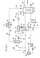
- FIG. 1 schematically shows a single-stage heat transformer 100, to which input heat is supplied from a heat source 102.
- the input heat can be in the exhaust steam from a steam turbine system, in a fluid heated by the waste heat of a gas turbine process or in the heat carrier of a flow or return line of a district heating system, a heat carrier heated by the waste heat from an engine or an industrial process, or one heated by concentrated solar heat (solar furnace) Heat transfer media should be included.
- the input heat from the heat source 102 is fed to a heat accumulator 114 via a heat transfer circuit, which contains a heat exchanger element 112 contained in the heat accumulator 114, which for the sake of simplicity is shown as a heat exchanger coil, but in practice it can be, for example, a fin or finned heat exchanger arrangement or the like. This also applies to the other in the drawings as heat exchange suppression T shown gen and designated heat exchanger elements.
- shut-off valves 108, 110 In the heat transfer circuit there are also two shut-off valves 108, 110 and, when using an initially vaporous heat transfer medium, such as steam, condensed in the heat exchanger coil 112, a storage vessel 107, as well as a feed pump 109, which feeds the heat transfer medium back to the heat source 102.
- an initially vaporous heat transfer medium such as steam
- a storage vessel 107 As well as a feed pump 109, which feeds the heat transfer medium back to the heat source 102.
- the heat accumulator 114 contains a zeolite as a sorbent and advantageously H 2 0 as a working medium.
- the temperature of the heat carrier in the heat exchanger coil 112 can be in the order of 100 ° C., for example between 80 and 110 ° C.
- the heat accumulator 114 can also contain a heat exchanger coil 116, through which a heat carrier is passed in order to extract the initial or useful heat.
- the heat exchanger coil 116 can, for example, supply heat to a district heating supply network.
- a working medium output line 118 is connected to the heat accumulator 114, which contains a valve 120 and leads to a condenser 122, which operates at a relatively low temperature and contains a heat exchanger 124, via which the waste heat resulting from the condensation to a cooling tower, a flow or the like.
- the condensed working medium which advantageously consists of water, then flows via a line 126, which contains a valve 128, into a storage vessel 130.
- the storage vessel 130 is connected via a line 132, which contains a pump 134, to the inlet of an evaporator 136 , the output of which is connected to a working medium input of the heat accumulator 114 via a working medium input line 138, which contains a shut-off or check valve 140.
- the evaporator 136 includes a heater coil 142, one. Includes input line 144 with a valve 146 and an output line 148 with a valve 150. The input line 144 and the output line 148 are connected to the parts of the lines 104 and 106 located between the heat source 102 and the valves 108 and 110, respectively.
- the line 132 can lead through a heat exchanger 152 connected into the outlet line 148.
- the working fluid input line 138 may include a compressor 154.
- the pieces of lines 104 located between heat exchanger coil 112 and valves 108 and 110, respectively and 106 may be connected to a line 156 containing a valve 158 and a line 160 containing a valve 162 and a circulation pump 164, respectively.
- the useful heat can also be removed via the heat exchanger coil 112.
- the heat transfer circuit leading through the heat source 102 and the heat transfer circuit containing the lines 156, 160 must contain the same heat transfer medium for the removal of the useful heat.
- valve positions, pump operating states, temperatures and pressures for the operation of the device shown in FIG. 1 when the heat accumulator 114 is loaded and discharged are given in Table 1.
- heat at a temperature level T 1 (eg 60 to 130 ° C.) from the heat source 102 is fed into the heat accumulator 114 via the heat exchanger coil 112 by means of a heat transfer fluid, which can be liquid H 2 O, for example.
- the heat accumulator contains a zeolite loaded with water as a storage medium in the fully or partially de-landed state. The heat supply expels water vapor from the zeolite, which flows via line 118 into condenser 122, condenses there and is collected in storage vessel 130.
- the heat exchanger 124 can be connected in a separate circuit which contains a cooling device working with river water or ambient air and, for example, with NH 3 or a fluorocarbon such as CCl 2 F 2 or CHClF 2 or the like. works as a heat transfer medium.
- the heat accumulator 114 When the heat accumulator 114 is discharged, that is to say when generating initial or useful heat, water is pumped into the evaporator 136 by means of the pump 134 and is evaporated there by heat from the heat source 102. The water vapor which is generated at a relatively high pressure corresponding to the temperature of the heat source 102 is absorbed in the zeolite in the heat accumulator 114. The resulting heat of absorption is conducted to the consumer via the heat exchanger coil 112 by means of the heat transfer fluid conveyed by the pump 164. If the useful heat transfer circuit works with a heat transfer fluid that is immiscible with the heat transfer fluid from the heat source 102, the useful heat is removed via the heat exchanger 116.
- the pressure of the working fluid which has a value p 0 (for example 0.01 bar) corresponding to the condenser temperature T 0 in the storage vessel 130, is increased by the pump 134 to a value p 1 (for example 1 bar) which corresponds to the temperature T 1 of the heat source 102 corresponds, increased in the evaporator 136.
- p 0 for example 0.01 bar
- p 1 for example 1 bar
- the heat exchanger 152 which is connected into the return line 148 of the heat transfer medium from the heat source 102.
- the preheating of the working fluid fed into the evaporator 136 results in a higher average temperature and thus a higher vapor pressure in the evaporator 136, which in turn increases the temperature level of the useful heat in the store 114 and also the gassing width and thus the efficiency for the zeolite in the store 114 results.
- the heat transfer medium in the heat exchanger coils 112 or 116 advantageously flows in the opposite direction to the heat transfer medium in the heat exchange coil 112 when the storage cylinder is loaded.
- a further advantageous development of the device according to FIG. 1 is to provide a heat exchanger coil 166 in the reservoir 130, which is connected to the line 104 via lines 168, 170 and a three-way valve 172 and serves to drain the water in the reservoir 130 by means of a partial flow of the Heat carrier from the flow line 104 from the heat source 102 to such an extent that the temperature in the storage vessel 130 is slightly higher than in the heat exchanger coil 142. Since the valve 128 is closed when the accumulator is discharged, that is to say when generating useful heat, this is sufficient pressure build-up in the reservoir 130 to convey the water into the evaporator 136 without the aid of the pump 134, so that a control valve can then be used instead of the pump 134.
- the heat exchanger 152 can then also be omitted. If the heat source 102 supplies steam as the heat transfer medium, the heat exchanger coil 166 will advantageously only use the superheating heat of the steam, so that the heat exchanger coil 142 is then supplied with almost saturated steam or wet steam.
- the three-way valve 172 shuts off the line 168 during the loading process (if desired, the line 170 can also contain a shut-off valve (not shown)), while during the unloading process it is set such that a desired part of the heat transfer stream from the heat source 102 flows through the heat exchanger coil 166 .
- the heat exchanger coil 112 For safety reasons, it may sometimes be appropriate to only charge the heat exchanger coil 112 with steam. So if the heat source 102 evaporates one Steam power plant supplies as a heat carrier, the heat exchanger coils 112 and 142 work as condensers. In this case, in order to prevent the power plant circuit from mixing with the district heating circuit, the useful heat (possibly also as steam) is better removed via the heat exchanger coil 116.
- the exhaust gases from a gas turbine or an engine are used as heat carriers from the heat source, cooling of these exhaust gases occurs in the heat exchanger coils 112 and 142.
- such exhaust gases can also be used to generate steam in a waste heat boiler, which then serves as a heat carrier for the input heat.
- the evaporator 136 can then be integrated into the waste heat boiler, ie the steam generated in this way can be introduced directly into the store 114 via the valve 140 during the discharge process.
- the accumulator 114 can be connected to a vacuum pump (not shown) via a line 174 provided with a shut-off valve.
- the heat exchanger coil 112 or 116 In order to utilize the storage capacity as completely as possible and in particular to even out the temperature of the initial or useful heat removed from the store, it is advantageous to provide the heat exchanger coil 112 or 116 with a plurality of outlets, as is shown, for example, in FIG. 2.
- the heat exchanger coil 112 is divided here into three sections 112a, 112b and 112c, which can be switched into the heat transfer circuit by lines with valves 176a, 176b and 176c.
- the heat exchanger coil 116 can be divided and connected accordingly.
- the segments of the store cooled by the connected sections 112a, 112b and 112c preferentially absorb the working fluid vapor offered by the evaporator 136.
- First valve 176 is opened, valves 176b and 176c remain closed.
- the water vapor is then preferably absorbed in the segment of the storage 114 which contains the section 112a and is cooled thereby.
- valve 176a is closed and valve 176b is opened.
- the segment of the store containing section 112a is then further discharged, but at the same time as much additional heat is withdrawn from the segment of the store containing section 112b as is necessary to achieve the desired outlet or flow temperature.
- valve 176b is then closed and the valve 176c is opened.
- This discharge mode is also advantageous if the storage e.g. was not fully loaded due to time constraints. Areas of different degrees of expulsion then arise when the working fluid is expelled during heat storage, which is highest at the entry point of the heat transfer medium from the heat source 102 and lowest at the exit point. By allowing the heat transfer medium to flow in the opposite direction to the loading and discharging the storage segment by segment, an optimal use of the storage can be achieved.
- heat accumulator 114 instead of the heat accumulator 114, two or more heat accumulators of the same type can be used, which can be connected in parallel in order to adapt to the fluctuations in load in the required number or can be operated as an expeller or absorber in order to implement quasi-continuous operation of the heat transformer 100 with a phase shift.
- the temperature level of the useful heat can first be increased by the compressor 154, which serves to increase the pressure of the working medium generated in the evaporator 136 (e.g. water vapor) and thus the temperature level of the useful heat generated during absorption.
- a compressor can also serve to increase the gassing width and thus the utilization and the efficiency of the storage 114 at a given useful heat temperature level.
- “Fumigation width” is understood to mean the difference in the concentration of the zeolite in absorbed working materials, such as water, in the loaded and unloaded state.
- FIG. 3 shows a modified part of the device according to FIG. 1.
- the same parts are provided with the same reference symbols.
- a compression heat pump 180 is switched on to increase the pressure and temperature level in the evaporator 136 and the fumigation width of the zeolite in the storage 114.
- the compression heat pump 180 includes an evaporator 182, which is supplied with heat by the heat transfer medium from the heat source 102.
- the evaporated working fluid of the compression heat pump is operated by a compressor 185 compresses and condenses in the heating coil 142 of the evaporator 136, which also works as a condenser of the compressor heat pump.
- the condensed working medium is conveyed back to the evaporator 182 by a throttle valve 184.
- the evaporation temperature in the evaporator 136 and the expulsion temperature in the storage 114 can also be increased by connecting the heat source 102 to a compressor heat pump, in which case the condenser heat of this compressor heat pump both the evaporator 136 and the heating or heat exchanger coil 112 with a higher value Heat operated (not shown).
- the continuously operating heat transformer 100 is connected upstream of the continuously operating heat transformer 100.
- This contains an expeller 214 a, a condenser 222, a pump 234, an evaporator 236 and an absorber 214b.
- An absorbent circuit 286 is also provided, which contains an expansion device 288 and a pump 290.
- the heat transformer 200 is a known device and is only shown schematically, for example the usual heat exchangers such as that between poor and rich solution in the absorption medium circuit are missing.
- the absorption heat is removed from the absorber 214b via a heat exchanger coil 216 and via a heat transfer circuit which contains a line 204, a heat exchanger 292 connected therein for the removal of useful heat, the heating coil 112 for the storage 114, a storage vessel 207 and a pump 209. Otherwise, the components of the discontinuously operating heat transformer are the same Reference numerals as in Fig. 1 provided.
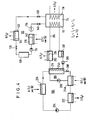
- heat Q (T 1 ) from heat source 102 (not shown in FIG. 4) is fed into expeller 214a and evaporator 236. Waste heat Q (T O ) at the temperature level T O is dissipated to the environment from the condenser 222. Useful heat Q (T 2 ) is generated in the absorber 214b at the temperature level T 2 . The heat Q (T 2 ) is withdrawn via the heat exchanger coil 216 and fed into the memory 114 via the heat exchanger coil 112, as has been explained with reference to FIG. 1. If desired, useful heat with the temperature level T 2 can also be removed from the heat exchanger 292 via a heat exchanger coil 294.
- the waste heat generated in the condenser 122 and the waste heat generated in the condenser 222 can be dissipated to the environment via a common cooling tower or a common flow cooling device or the like.
- the absorption of the expelled working substance in the storage 114 and the removal of the useful heat generated thereby are carried out, as has been described with reference to FIG. 1.
- the heat of vaporization for the evaporator 136 is taken from the heat source (102 in FIG. 1) not shown in FIG. 4. Overall, this results in a temperature level T 3 which is higher than T 2 for the useful heat removed, for example, via the heat exchanger coil 116.
- the theoretical efficiency of the device as a whole is approximately 1/3, ie approximately one third of the total amount of heat that is supplied to the devices 214a, 236 and 136 at the temperature level T 1 can be extracted as useful heat at the temperature level T 3 .
- a further increase in the temperature level T 3 of the useful heat that can be taken from the storage 114 can be achieved in that the evaporator 136 is not supplied with heat from Q (T 1 ) of the temperature T 1 from the heat source 102, but with heat Q (T 2 ) from absorber 214b.
- the device according to FIG. 4 can be modified as shown in FIG. 5.
- the heat transformer 100 on the right side of FIG. 5 is only shown in part and is otherwise designed in accordance with FIG. 1.
- the heat transfer medium from the heat exchanger coil 216 is thus conducted via the lines 144 and 148 through the heating coil 142 of the evaporator 136, as was explained with reference to FIG. 1.
- 5 increases the temperature level T 3 of the useful heat Q (T 3 ) which can be taken from the storage 114, but the theoretical efficiency is reduced to about 1/4.
- the heat exchanger coil 294 and the heat exchanger coil 116 can be connected in series, which is advantageous if the useful heat is used to remove a liquid heat transfer medium such as water from a temperature below T 2 to heat to the temperature T 3 (starting temperature of the heat accumulator 114).
- the evaporator 136 (FIGS. 1 and 5) of the discontinuously operating heat pump of the heat transformer 100 can be placed in the absorber 214 b (FIG. 4) of the continuously operating one warmth Integrate the heat transformer 200 pump.
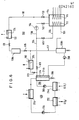
- FIG. 6 the discontinuously operating heat transformer, which corresponds to the heat transformer 100 in FIGS. 1 and 5, with 300 and the continuously working heat transformer with 400. Parts of the same function are designated by the same reference numerals in FIGS. 1, 5 and 6.
- the output side of the heat exchanger coil 216 is connected via a valve 611 to a line 204 which contains a further valve 613 and leads to the input side of the heating or heat exchanger coil 112 of the store 114. Between the valves 611 and 613 branches off the working fluid inlet line 138 containing the valve 140 (and, if desired, the compressor 154).
- the outlet side of the valve 128 is connected to a first storage vessel, the outlet of which is connected via a valve 615 and a line 617 to a second storage vessel 130b, into which the outlet line 106 of the heat exchanger coil 112 also opens.
- the heat exchanger 292 is connected with an input side via a valve 619 to the output side of the heat exchanger coil 216 and with its output side. connected to line 617.
- the heat generated in the absorber 214b of the continuous heat transformer 400 is used, on the one hand, via the heat exchanger coil 112 to expel the water vapor from the zeolite contained in the storage 114 and also to generate water vapor for absorption and production of useful heat in the storage 114.
- the valve positions and temperatures of the various units 6 are listed in Table 2.
- the heat exchanger 292 enables this Extraction of useful heat at the temperature level of the absorber 214b.
- the outgassing pressure can be selected so that the waste heat in the condenser 122 arises at such a high temperature level that this heat is still suitable for feeding into the evaporator 236 and / or the expeller 214a, which results in a theoretical power factor of 1/3 .
- both heat from the condenser 122 at the temperature level T 1 ′ and heat from the heat source 102 at the temperature level T 1 are fed into the evaporator 236 and / or the expeller 214a.
- Useful heat at the temperature level of the absorber 214b can be taken from the heat exchanger 292 via the heat exchanger coil 294; the heat exchanger coil 294 can also be connected upstream of the heat exchanger coil 116.
- the valve 615 is necessary because the reservoir 130b is at a higher pressure than the condensate from the condenser 122 in the reservoir 130a during the expulsion.
- the continuous heat transformer 200 and 400 are in operation both during the drive-out cycle and during the absorption cycle of the store 114.
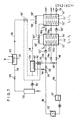
- FIG. 7 shows a device which contains a combination of a discontinuously operating heat transformer with an upstream, likewise discontinuously operating heat transformer. the condenser 124 and the evaporator 136 being common to both heat transformers.
- the device according to FIG. 7 contains two series-connected, discontinuously operating heat transformers of the type explained with reference to FIG. 1, and the same reference numbers as in FIG. 1 were therefore also used.
- the same reference numbers as in FIG. 1 were therefore also used.
- one or two dashes are added to the relevant reference symbols. The same applies to components that are required for each of the two heat transformers.
- valves are designated which enable the loading or unloading of the stores 114 'or 114 "explained in sections with reference to FIG. 2.
- the memory 114 ' is charged by heat of the temperature T 1 from the heat source 102 via the heat exchanger coil 112'.
- Working vapor is then generated by evaporation in the evaporator 136 by means of heat from the heat source 102, with which the heat accumulator 114 ′ is discharged.
- the heat generated when the working medium is sorbed in the absorbent in the storage 114 ' is coupled out via the heat exchanger coil 116' and fed to the heat exchanger coil 112 "of the storage 114", where the heat is used to expel the working medium from the absorbent contained in the heat accumulator 114 ".
- the heat for the evaporator 136 is removed by a heat transfer circuit which contains the heat exchanger coil 112 'and the pump 134 ".
- an additional valve 101 is provided in line 104
- the pressure in the evaporator 136 and thus the useful heat level in the absorption in the heat store 114 ′′ are increased further, but at the expense of the efficiency.
- Zeolites of types A, X and Y have proven to be particularly suitable.
Abstract
Description
Die vorliegende Erfindung betrifft ein Verfahren zum Speichern und Hochtransformieren der Temperatur von Wärme, bei welchem ein Arbeitsmittel durch Wärme eines vorgegebenen mittleren Temperaturbereichs aus einem Absorptionsmittel ausgetrieben wird, der bei Austreiben entstehende Arbeitsmitteldampf bei einer relativ niedrigen Temperatur kondensiert wird und das kondensierte Arbeitsmittel im mittleren Temperaturbereich verdampft sowie bei erhöhtem Druck unter Erzeugung von Absorptionswärme einer relativ hohen Temperatur im Absorptionsmittel absorbiert wird. Ferner betrifft die Erfindung Einrichtungen zur Durchführung eines solchen Verfahrens.The present invention relates to a method for storing and transforming up the temperature of heat, in which a working fluid is expelled from an absorbent by heat of a predetermined medium temperature range, the working fluid vapor which is produced during the expulsion is condensed at a relatively low temperature, and the condensed working fluid in the medium temperature range evaporates and is absorbed at elevated pressure to generate absorption heat of a relatively high temperature in the absorbent. The invention further relates to devices for carrying out such a method.
Für Einrichtungen, die mit Betriebs- oder Eingangswärme mit Temperaturen in einem mittleren Temperaturbereich gespeist werden und einerseits Nutz- oder Ausgangswärme auf einem höheren Temperaturniveau sowie Abwärme auf einem niedrigeren Temperaturniveau liefern, hat sich der Begriff "Wärmetransformator" eingebürgert. Dieser Begriff soll auch hier in dem angegebenen Sinne verwendet werden.For facilities with operating or input heat with temperatures in a medium temperature range are fed and, on the one hand, supply useful or output heat at a higher temperature level and waste heat at a lower temperature level, the term "heat transformer" has become established. This term should also be used here in the sense given.
Ein kontinuierlich betriebener Wärmetransformator wurde schon von K. Nesselmann in der Veröffentlichung "Zur Theorie der Wärmetransformation", Wissenschaftliche Veröffentlichung Siemens-Konzern 12 (1933), Heft 2, S. 89-109 diskutiert. Kontinuierlich arbeitende Wärmetransformatoren sind ferner aus DE-B-10 20 997 sowie DE-A-25 54 937, 26 29 441, 26 35 557 und 27 27 990 bekannt.A continuously operated heat transformer has already been discussed by K. Nesselmann in the publication "On the theory of heat transformation", scientific publication Siemens Group 12 (1933), Issue 2, pp. 89-109. Continuously operating heat transformers are also known from DE-B-10 20 997 and DE-A-25 54 937, 26 29 441, 26 35 557 and 27 27 990.
Der Wärmetransformator gemäß DE-A-25 54 937 soll dazu dienen, die Abwärme eines Kraftwerkes auf ein höheres Temperaturniveau zu heben. Als Arbeitsmittel wird NH3 verwendet.The heat transformer according to DE-A-25 54 937 is intended to raise the waste heat of a power plant to a higher temperature level. NH 3 is used as the working medium.
Der aus DE-A-26 35 557 bekannte Wärmetransformator arbeitet mit dem Arbeitsstoffsystem NH3/H20/Propan.The heat transformer known from DE-A-26 35 557 works with the working material system NH 3 / H 2 0 / propane.
Auch zeitlich diskontinuierlich ("periodisch") arbeitende Wärmetransformatoren sind bekannt, z.B. aus DE-A-26 29 441, 27 58 727 und 28 08 464.Heat transformers operating intermittently ("periodically") are also known, e.g. from DE-A-26 29 441, 27 58 727 and 28 08 464.
Der aus DE-A-26 29 441 bekannte Wärmetransformator soll zur Krafterzeugung dienen, wobei große Mengen Ammoniak gespeichert werden müssen. In DE-A-27 58 727 wird ein als mehrstufiger Speicher betriebener Wärmetransformator angegeben, ohne daß jedoch nähere Angaben gemacht werden, wie der Betrieb erfolgen soll. Als Speichermedium dient Na2S, das gefährlich ist und keine Temperaturen über 80°C zuläßt. Der Wärmetransformator, der in DE-A-28 08 464 beschrieben ist, enthält eine spezielleThe heat transformer known from DE-A-26 29 441 is intended to generate force, with large amounts of ammonia having to be stored. DE-A-27 58 727 specifies a heat transformer operated as a multi-stage store, but without specifying how the operation is to be carried out. Na 2 S serves as the storage medium, which is dangerous and does not allow temperatures above 80 ° C. The heat transformer, which is described in DE-A-28 08 464, contains a special one
Kombination zweier zeitlich diskontinuierlich betriebener Speicher und dient zur Speicherung und Hochtransformierung von Sonnenwärme von 35°C auf ca. 70°C. Als Arbeitsmittel soll Methylamin verwendet werden, was nicht nur giftig ist, sondern sich auch leicht zersetzt. Als Speicher- oder Absorptionsmittel sind CaCl2 und LiC1 vorgesehen. Die angegebenen Einrichtungen sind sehr kompliziert und benötigen viele Wärmetauscher, was den Wirkungsgrad beeinträchtigt.Combination of two intermittently operated storage systems and is used for storing and transforming solar heat from 35 ° C to approx. 70 ° C. Methylamine should be used as the working medium, which is not only toxic, but also easily decomposes. CaCl 2 and LiC1 are provided as storage or absorption media. The specified facilities are very complicated and require many heat exchangers, which affects the efficiency.
Ferner könnten Metallhydride als Arbeitsstoffsystem verwendet werden. Das Arbeitsstoffsystem Metall/Wasserstoff läßt sich jedoch nur bei einem Wärmetransformator verwenden, der nach dem Resorberprinzip arbeitet, was mit einem erheblichen technischem Aufwand verbunden ist. Bei Verwendung von Wasserstoffgas besteht außerdem immer eine gewisse Explosionsgefahr und die Schwellung der Hydride bei der Wasserstoffaufnahme bringt technisch nur schwer zu lösende Probleme mit sich.Metal hydrides could also be used as the working material system. However, the metal / hydrogen working substance system can only be used with a heat transformer that works according to the absorber principle, which is associated with considerable technical outlay. When using hydrogen gas, there is always a certain risk of explosion, and the swelling of the hydrides during the hydrogen uptake poses problems that are difficult to solve technically.
Wärmetransformatoren werden für viele Zwecke benötigt: Wärmeversorgung und Krafterzeugung sind oft miteinander gekoppelt z.B. bei Heizkraftwerken, bei Diesel- und Gasmotoren, die Generatoren oder Kompressorwärmepumpen antreiben und deren. Abwärme genutzt wird, bei der Prozeßwärmeversorgung, z.B. in der chemischen und Nahrungsmittelindustrie. Wegen des zeitlich'sehr unterschiedlich strukturierten Wärme- und Kraftbedarfes benötigt man einerseits effektive Wärmespeicher. Andererseits muß häufig das Temperaturniveau der zur Verfügung stehenden Wärme erhöht werden, um diese Wärme nutzen zu können. Zum Beispiel werden Heizkraftwerke im allgemeinen hinsichtlich der Elektrizitätserzeugung mit optimalem Wirkungsgrad betrieben, was bedeutet, daß die Abwärme auf einem möglichst niedrigen Temperaturniveau anfallen soll. Bei der Fernwärmeversorgung muß dagegen die Vorlauftemperatur des Wärmeträgers einen gewissen, mit zunehmendem Fernwärmebedarf ansteigenden Mindestwert haben. Diese Forderung läßt sich bei direkter Einspeisung der Abwärme des Kraftwerkes in das Fernwärmenetz nur auf Kosten des Wirkungsgrades des Kraftwerkes erfüllen. Ein Speicher, der während Bedarfsspitzen des Fernwärmenetzes Wärme auf einem Niveau liefert, das höher ist als das Beladungsniveau (Beladung z.B. nachts mit 100°C und Wärmeabgabe zu Spitzehlastzeiten mit 130°C'bis 150°C) ergäbe also eine erhebliche Verbesserung des Gesamtwirkungsgrades des Wärmekraftwerkes und der Fernwärmeversorgung. Bei Gas-und Dieselmotor-Heizkraftwerken fällt im Kühlkreislauf der Antriebsmaschine Wärme bei 80°C bis 100°C an.- Auch dieses Temperaturniveau ist für ein Fernwärmenetz oder für Prozeßwärme zu niedrig, da hier oft Vorlauftemperaturen zwischen 120 und 150°C benötigt werden. Auch hier wird ein Speicher benötigt, der nicht nur einen Ausgleich für schwankende Nachfrage liefert, sondern zusätzlich die Wärme auf einem höheren Temperaturniveau abzugeben vermag als sie eingespeichert worden ist.Heat transformers are needed for many purposes: heat supply and power generation are often coupled with each other, for example in thermal power stations, in diesel and gas engines that drive generators or compressor heat pumps and their. Waste heat is used in the process heat supply, for example in the chemical and food industries. On the one hand, effective heat storage is required because of the very differently structured heat and power requirements. On the other hand, the temperature level of the available heat often has to be increased in order to be able to use this heat. For example, thermal power plants are generally operated with optimal efficiency in terms of electricity generation, which means that the waste heat should be generated at the lowest possible temperature level. In contrast, the supply temperature of the heat transfer medium must be certain for the district heating supply must have increasing minimum value with increasing district heating demand. This requirement can only be met if the waste heat from the power plant is fed directly into the district heating network at the expense of the efficiency of the power plant. A storage system that supplies heat at a level that is higher than the load level during peak loads of the district heating network (e.g. load at night with 100 ° C and heat output during peak load periods with 130 ° C to 150 ° C) would result in a significant improvement in the overall efficiency of the Thermal power plant and district heating supply. In gas and diesel engine thermal power stations, heat is generated in the cooling circuit of the drive machine at 80 ° C to 100 ° C. This temperature level is too low for a district heating network or for process heat, since flow temperatures between 120 and 150 ° C are often required here. Here too, a store is required that not only provides compensation for fluctuating demand, but also can deliver the heat at a higher temperature level than it has been stored.
Bei kommunalen Fernwärmenetzen zur Deckung des privaten Wärmebedarfs sowie bei der industriellen Fernwärmeversorgung muß, wie erwähnt, in Spitzenlastzeiten die Vorlauftemperautr angehoben werden, um den Wärmebedarf voll decken zu können. Eine höhere Vorlauftemperatur führt jedoch nicht nur zu einem schlechteren Wirkungsgrad bei der Krafterzeugung, sondern auch zu höheren Verlusten im Fernwärmeleitungsnetz. Hier könnte'ein beim Verbraucher aufgestellter Wärmespeicher Abhilfe schaffen, der in Zeiten niedrigen Wärmebedarfs aufgeladen wird und in Hochlastzeiten Ausgangswärme mit einer Temperatur liefert, die höher als die der zum Beladen verwendeten Eingangswärme ist. Hierdurch würde sich nicht nur die Anhebung der Vorlauftemperatur des Fernwärmenetzes ganz oder zumindest teilweise erübrigen, sondern auch die Investitionskosten im Fernwärmenetz verringern, da dieses gleichmäßiger belastet wird. Solche Speicher könnten an Netzknotenpunkten oder direkt bei den einzelnen Verbrauchern stehen und mit Wärme entweder aus dem Vorlaufstrang und/oder aus dem Rücklaufstrang beladen werden.In municipal district heating networks to cover private heating requirements and in industrial district heating supply, as mentioned, the flow temperature must be increased during peak load times in order to be able to fully cover the heating requirement. However, a higher flow temperature not only leads to poorer efficiency in power generation, but also to higher losses in the district heating network. This could be remedied by a heat store installed at the consumer, which is charged in times of low heat demand and delivers output heat at a high level which is higher than the input heat used for loading. This would not only completely or at least partially eliminate the increase in the flow temperature of the district heating network, but would also reduce the investment costs in the district heating network. because it is loaded more evenly. Such storage units could be located at network nodes or directly at the individual consumers and could be loaded with heat either from the flow line and / or from the return line.
In der Industrie fällt häufig Abwärme an, die nicht mehr genutzt werden kann, da sie eine zu niedrige Temperatur hat und/oder im Zeitpunkt des Entstehens und/oder am Ort des Entstehens nicht benötigt wird. Auch hier lassen sich diskontinuierliche Wärmetransformatoren mit Vorteil zum Speicher, Hochtransformieren des Temperaturniveaus und gegebenenfalls Transport von Wärme verwenden.Waste heat is often generated in industry, which can no longer be used because it is too low and / or is not required at the time it is generated and / or at the place where it is generated. Here, too, discontinuous heat transformers can be used advantageously for storage, step-up transformation of the temperature level and, if necessary, transport of heat.
In all den genannten Fällen, insbesondere für Speicher-Wärme-Transformatoren, die in der Nähe von Verbrauchern, z.B. in Wohnhäusern, Werkhallen und Büros stehen, ist es unerläßlich, daß das verwendete Arbeitsstoffsystem aus umweltfreundlichen und ungefährlichen Substanzen besteht. Diese Substanzen müssen gleichzeitig so beschaffen sein,. daß Ausgangs- oder Nutzwärme auf höherem Temperaturniveau, z.B. 100 bis 150°C oder sogar 200 bis 250°C erzeugt werden kann.In all of the above cases, especially for storage heat transformers that are close to consumers, e.g. stand in homes, workshops and offices, it is essential that the working material system consists of environmentally friendly and harmless substances. These substances must be of the same type. that output or useful heat at a higher temperature level, e.g. 100 to 150 ° C or even 200 to 250 ° C can be generated.
Der vorliegenden Erfindung liegt'also die Aufgabe zugrunde, einen Speicher-Wärmetransformator anzugeben, der im Gegensatz zum Stand der Technik mit umweltfreundlichen und ungefährlichen Stoffen arbeitet und außerdem im Gegensatz zum Stand der Technik, auch höhere Ausgangs-oder Nutzwärmetemperaturen als 100°C, insbesondere Ausgangstemperaturen über 150°C bis 250°C oder sogar 300 °C zu liefern vermag.The present invention is therefore based on the object of specifying a storage heat transformer which, in contrast to the prior art, works with environmentally friendly and harmless substances and, in contrast to the prior art, also has starting or useful heat temperatures higher than 100 ° C., in particular It is capable of delivering starting temperatures above 150 ° C to 250 ° C or even 300 ° C.
Die Erfindung löst diese Aufgabe durch ein Verfahren zum Speichern und Hochtransformieren der Temperatur von Wärme, bei welchem ein Arbeitsmittel durch Wärme eines vorgegebenen mittleren Temperaturbereichs aus einem Absorptionsmittel ausgetrieben wird, der beim Austreiben entstehende Arbeitsmitteldampf bei einer relativ niedrigen Temperatur kondensiert wird und das kondensierte Arbeitsmittel im mittleren Temperaturbereich verdampft sowie bei erhöhtem Druck unter Erzeugung von Absorptionswärme einer relativ hohen Temperatur im Absorptionsmittel absorbiert wird, das dadurch gekennzeichnet ist, daß als Absorptionsmittel ein Zeolith und als Arbeitsmittel Wasser verwendet wird.The invention solves this problem by a method for storing and transforming the temperature of heat, in which a working medium is expelled from an absorption medium by heat of a predetermined medium temperature range, the working medium vapor produced during the expulsion is condensed at a relatively low temperature and the condensed working medium in evaporated middle temperature range and is absorbed at elevated pressure with the generation of heat of absorption of a relatively high temperature in the absorbent, which is characterized in that a zeolite is used as the absorbent and water as the working medium.
Weiterbildungen des erfindungsgemäßen Verfahrens und vorteilhafte Einrichtungen zur Durchführung des Verfahrens gemäß der Erfindung sind in den Unteransprüchen gekennzeichnet.Further developments of the method according to the invention and advantageous devices for carrying out the method according to the invention are characterized in the subclaims.
Bei den Verfahren und Einrichtungen gemäß der Erfindung wird also das Arbeitsstoffsystem Zeolith/H2O verwendet. Dieses Arbeitsstoffsystem ist umweltfreundlich und ungiftig, so daß keine kostspieligen Sicherheitsvorkehrungen erforderlich sind und eine Verwendung auch in öffentlich zugänglichen Bereichen möglich ist. Außerdem hat gerade dieses erfindungsgemäß in einem Wärmetransformator verwendete Arbeitsstoffsystem den Vorteil, daß die gewünschte Nutzwärme Temperaturen von mindestens 130 °C, insbesondere über 150 °C bis 250 °C und gegebenenfalls sogar bis 300 °C und darüber mit gutem Wirkungsgrad erreichbar sind.The zeolite / H 2 O working substance system is therefore used in the methods and devices according to the invention. This working material system is environmentally friendly and non-toxic, so that no expensive safety precautions are necessary and can also be used in publicly accessible areas. In addition, this working material system used according to the invention in a heat transformer has the advantage that the desired useful heat temperatures of at least 130 ° C, in particular above 150 ° C to 250 ° C and possibly even up to 300 ° C and above can be achieved with good efficiency.
Zeolith/H2o als Arbeitsstoffsystem ist bisher nur bei einer mit Niedertemperaturwärme, wie Sonnenwärme, betriebenen Kühlanlage (US-A-40 34 569).und bei einer Klein-Klimaanlage (US-A-41 21 432, die mit Verdampfer- bzw. Kondensatortemperaturen von ca. 4 °C bzw. 43 °C arbeitet. Die dort angegebenen Verfahren und die angegebenen Temperatur- und Druckbereiche lassen aber nicht erkennen, daß das Arbeitsstoffsystem Zeolith/ H20 in einem Wärmetransformator zur Speicherung von Wärme und zur Erzeugung von Nutzwärme mit einem Temperaturniveau bis zu 300 °C und darüber eingesetzt werden kann.So far, zeolite / H 2 o as a working material system has only been used in a cooling system (US-A-40 34 569) operated with low-temperature heat, such as solar heat, and in a small air conditioning system (US-A-41 21 432, which is equipped with an evaporator or Condenser temperatures of approximately 4 ° C or 43 ° C. The procedures specified there and the specified However, given temperature and pressure ranges do not indicate that the zeolite / H 2 0 working fluid system can be used in a heat transformer for storing heat and for producing useful heat at a temperature level of up to 300 ° C. and above.
Im folgenden werden Ausführungsbeispiele der Erfindung unter Bezugnahme auf die Zeichnung näher erläutert.Exemplary embodiments of the invention are explained in more detail below with reference to the drawing.
Es zeigen:
- Fig. 1 einen einstufigen Wärmetransformator mit verschiedenen Vorrichtungen zur Verbesserung des Wirkungsgrades, der nach dem Verfahren gemäß der Erfindung arbeitet;
- Fig. 2 eine Vorrichtung zur Entnahme von Wärme aus einem Speicher des Wärmetransformators gemäß Fig. 1;
- Fig. 3 eine Einrichtung, die einen zeitlich diskontinuierlich arbeitenden Wärmetransformator in Kombination mit einer Kompressorwärmepumpe enthält;
- Fig. 4, 5 und 6 Ausführungsformen von nach dem erfindungsgemäßen Verfahren arbeitenden Einrichtungen, die einen kontinuierlich arbeitenden Wärmetransformator in Kombination mit einem diskontinuierlich arbeitenden Wärmetransformator enthalten, und
- Fig. 7 eine nach dem erfindungsgemäßen Verfahren arbeitende Einrichtung, die zwei diskontinuierlich arbeitende Wärmetransformatoren enthält.
- 1 shows a single-stage heat transformer with various devices for improving the efficiency, which works according to the method according to the invention.
- FIG. 2 shows a device for extracting heat from a memory of the heat transformer according to FIG. 1;
- 3 shows a device which contains a heat transformer which operates in a discontinuous manner in combination with a compressor heat pump;
- 4, 5 and 6 embodiments of devices operating according to the method of the invention, which contain a continuously operating heat transformer in combination with a discontinuously operating heat transformer, and
- 7 shows a device operating according to the method according to the invention, which contains two discontinuously operating heat transformers.
Fig. 1 zeigt schematisch einen einstufigen Wärmetransformator 100, dem Eingangswärme von einer Wärmequelle 102 zugeführt wird. Die Eingangswärme kann im Abdampf von einer Dampfturbinenanlage, in einem durch die Abwärme eines Gasturbinenprozesses aufgeheizten Fluid oder im Wärmeträger einer Vorlauf- oder Rücklaufleitung einer Fernheizungsanlage, einem durch die Abwärme eines Motors oder eines industriellen Prozesses erwärmten Wärmeträger oder einem durch konzentrierte Sonnenwärme (Sonnenofen) aufgeheizten Wärmeträger enthalten sein. Die Eingangswärme von der Wärmequelle 102 wird einem Wärmespeicher 114 über einen Wärmeträgerkreislauf zugeführt, der ein im Wärmespeicher 114 enthaltenes Wärmetauscherelement 112 enthält, das der Einfachheit halber als Wärmetauscherschlange dargestellt ist, jedoch in der Praxis z.B. eine Rippen-oder Lamellenwärmetauscheranordnung oder dgl. sein kann. Dies gilt auch für die anderen in den Zeichnungen als WärmetauscherschlaTgen dargestellten und bezeichneten Wärmetauscherelemente.1 schematically shows a single-
Im Wärmeträgerkreislauf befinden sich ferner zwei Absperrventile 108, 110 sowie bei Verwendung eines anfänglich dampfförmigen und in der Wärmetauscherschlange 112 kondensierten Wärmeträgers, wie Dampf, ein Vorratsgefäß 107, sowie eine Speisepumpe 109, die den Wärmeträger wieder zur Wärmequelle 102 zurückfördert.In the heat transfer circuit there are also two shut-off
Der Wärmespeicher 114 enthält einen Zeolith als Sorp- tionsmittel und vorteilhafterweise H20 als Arbeitsmittel. Die Temperatur des Wärmeträgers in der Wärmetauscherschlange 112 kann in der Größenordnung von 100 °C, beispielsweise zwischen 80 und 110 °C liegen. Der Wärmespeicher 114 kann ferner eine Wärmetauscherschlange 116 enthalten, durch die ein Wärmeträger zur Entnahme der Ausgangs- oder Nutzwärme geleitet wird.The
Die Wärmetauscherschlange 116 kann beispielsweise Wärme an ein Fernwärmeversorgungsnetz liefern.The
An den Wärmespeicher 114 ist eine Arbeitsmittel-Ausgangsleitung 118 angeschlossen, die ein Ventil 120 enthält und zu einem Kondensator 122 führt, der auf relativ niedriger Temperatur arbeitet und einen Wärmetauscher 124 enthält, über den die bei der Kondensation entstehende Abwärme an einen Kühlturm, einen Fluß oder dgl. abgeführt wird. Das kondensierte Arbeitsmittel, das vorteilhafterweise aus Wasser besteht, fließt dann über eine Leitung 126, die ein Ventil 128 enthält, in ein Vorratsgefäß 130. Das Vorratsgefäß 130 ist über eine Leitung 132, die eine Pumpe 134 enthält, mit dem Eingang eines Verdampfers 136 verbunden, dessen Ausgang über eine Arbeitsmitteleingangsleitung 138, die ein Absperr- oder Rückschlagventil 140 enthält, mit einem Arbeitsmitteleingang des Wärmespeichers 114 verbunden ist.A working
Der Verdampfer 136 enthält eine Heizschlange 142, die eine. Eingangsleitung 144 mit einem Ventil 146 sowie eine Ausgangsleitung 148 mit einem Ventil 150 enthält. Die Eingangsleitung 144 und die Ausgangsleitung 148 sind mit den zwischen der Wärmequelle 102 und den Ventilen 108 bzw. 110 liegenden Teilen der Leitungen 104 bzw. 106 verbunden.The
Zur Erhöhung des Wirkungsgrades kann die Leitung 132 durch einen in die Ausgangsleitung 148 geschalteten Wärmetauscher 152 führen.To increase the efficiency, the
Die Arbeitsmitteleingangsleitung 138 kann einen Kompressor 154 enthalten.The working
Die zwischen der Wärmetauscherschlange 112 und den Ventilen 108 bzw. 110 gelegenen Stücke der Leitungen 104 und 106 können mit einer Leitung 156, die ein Ventil 158 enthält bzw. einer Leitung 160, die ein Ventil 162 sowie eine Umwälzpumpe 164 enthält, verbunden sein. Hierdurch kann die Nutzwärme auch über die Wärmetauscherschlange 112 entnommen werden. Selbstverständlich muß in diesem Falle der durch die Wärmequelle 102 führende Wärmeträgerkreislauf und der die Leitungen 156, 160 enthaltende Wärmeträgerkreislauf zur Entnahme der Nutzwärme das gleiche Wärmeträgermedium enthalten.The pieces of
Die Ventilstellungen, Pumpenbetriebszustände, Temperaturen und Drücke für den Betrieb der in Fig. 1 dargestellten Einrichtung bei Beladung und Entladung des Wärmespeichers 114 sind in Tabelle 1 angegeben.The valve positions, pump operating states, temperatures and pressures for the operation of the device shown in FIG. 1 when the
Beim Entladen wird Wärme auf einem Temperaturniveau T1 (z.B. 60 bis 130 °C) aus der Wärmequelle 102 mittels eines Wärmeträgerfluids, das z.B. flüssiges H20 sein kann, über die Wärmetauscherschlange 112 in den Wärmespeicher 114 eingespeist. Der Wärmespeicher enthält im ganz oder teilweise entlandenen Zustand einen mit Wasser beladenen Zeolith als Speichermedium. Durch die Wärmezufuhr wird Wasserdampf aus dem Zeolith ausgetrieben, der über die Leitung 118 in den Kondensator 122 strömt, dort kondensiert und im Vorratsgefäß 130 gesammelt wird. Der Wärmetauscher 124 kann in einen eigenen Kreislauf geschaltet sein, der eine mit Flußwasser oder Umgebungsluft arbeitende Kühlvorrichtung enthält und z.B. mit NH3 oder einem Fluor-Kohlenstoff, wie CCl2F2 oder CHClF2 oder-dgl. als Wärmeträger arbeitet.During unloading, heat at a temperature level T 1 (eg 60 to 130 ° C.) from the
Beim Entladen des Wärmespeichers 114, also bei der Erzeugung von Ausgangs- oder Nutzwärme, wird mittels der Pumpe 134 Wasser in den Verdampfer 136 gefördert und dort durch Wärme aus der Wärmequelle 102 verdampft. Der Wasserdampf, der mit einem der Temperatur der Wärmequelle 102 entsprechenden relativ hohen Druck entsteht, wird im Zeolith im Wärmespeicher 114 absorbiert. Die dabei entstehende Absorptionswärme wird über die Wärmetauscherschlange 112 mittels des durch die Pumpe 164 geförderten Wärmeträgerfluids zum Verbraucher geleitet. Falls der Nutzwärmeträgerkreislauf mit einem Wärmeträgerfluid arbeitet, das mit dem Wärmeträgerfluid von der Wärmequelle 102 nicht mischbar ist, wird die Nutzwärme über den Wärmetauscher 116 entnommen.When the
Der Druck des Arbeitsmittels, der im Vorratsgefäß 130 einen der Kondensatortemperatur T0 entsprechenden Wert p0 (z.B. 0,01 bar) hat, wird durch die Pumpe 134 auf einen Wert p1 (z.B. 1 bar),der der Temperatur T1 der Wärmequelle 102 entspricht, im Verdampfer 136 erhöht. Dadurch erfolgt die Absorption des Arbeitsmitteldampfes im Zeolith bei entsprechend hohem Druck und dementsprechend wird die Absorptionswärme bei der erwünschten hohen Temperatur frei.The pressure of the working fluid, which has a value p 0 (for example 0.01 bar) corresponding to the condenser temperature T 0 in the
Es ist vorteilhaft, das durch die Pumpe 134 aus dem Sammelgefäß 130 geförderte Arbeitsmittel vor dem Eintritt in den Verdampfer 136 zu erwärmen. Dies geschieht zweckmäßigerweise durch den Wärmetauscher 152, der in die Rücklaufleitung 148 des Wärmeträgermediums von der Wärmequelle 102 geschaltet ist. Durch die Vorwärmung des in den Verdampfer 136 eingespeisten Arbeitsmittels wird eine höhere mittlere Temperatur und damit ein höherer Dampfdruck im Verdampfer 136 erreicht, was wiederum eine Erhöhung des Temperaturniveaus der Nutzwärme im Speicher 114 und auch der Begasungsbreite und damit des Wirkungsgrades für den Zeolith im Speicher 114 ergibt.It is advantageous to heat the working medium conveyed out of the collecting
Bei der Entnahme der Nutzwärme aus dem Speicher 114 strömt der Wärmeträger in den Wärmetauscherschlangen 112 bzw. 116 vorteilhafterwiese in entgegengesetzter Richtung wie der Wärmeträger in der Wärmetauscherschlange 112 beim Beladen des Speichers.When the useful heat is removed from the
Eine weitere vorteilhafte Weiterbildung der Einrichtung gemäß Fig. 1 besteht darin, im Vorratsbehälter 130 eine Wärmetauscherschlange 166 vorzusehen, die über Leitungen 168, 170 und ein Dreiwegeventil 172 an die Leitung 104 angeschlossen ist und dazu dient, das Wasser im Vorratsbehälter 130 mittels eines Teilstromes des Wärmeträgers aus der Vorlaufleitung 104 von der Wärmequelle 102 soweit aufzuwärmen, daß die Temperatur im Vorratsgefäß 130 etwas höher ist als in der Wärmetauscherschlange 142. Da das Ventil 128 beim Entladen des Speichers, also bei der Erzeugung von Nutzwärme, geschlossen ist, genügt dann der sich im Vorratsgefäß 130 aufbauende Druck, um das Wasser ohne Mithilfe der Pumpe 134 in den Verdampfer 136 zu fördern, so daß anstelle der Pumpe 134 dann ein Regelventil verwendet werden kann. Auch der Wärmetauscher 152 kann dann entfallen. Falls die Wärmequelle 102 Dampf als Wärmeträgermedium liefert, wird man in der Wärmetauscherschlange 166 vorteilhafterweise nur die Überhitzungswärme des Dampfes benutzen, so daß dann der Wärmetauscherschlange 142 nahezu gesättigter Dampf oder Naßdampf zugeführt wird. Das Dreiwegeventil 172 sperrt die Leitung 168 beim Beladungsvorgang ab, (gewünschenfalls kann auch die Leitung 170 ein Absperrventil (nicht dargestellt) enthalten), während es beim Entladungsvorgang so eingestellt wird, daß ein gewünschter Teil des Wärmeträgerstroms aus der Wärmequelle 102 durch die Wärmetauscherschlange 166 fließt.A further advantageous development of the device according to FIG. 1 is to provide a
Aus Sicherheitsgründen kann es manchmal zweckmäßig sein, die Wärmetauscherschlange 112 nur mit Dampf zu beschicken. Wenn also die Wärmequelle 102 Abdampf eines Dampfkraftwerks als Wärmeträger liefert, so arbeiten die Wärmetauscherschlangen 112 bzw. 142 als Kondensatoren. Um eine Mischung des Kraftwerkkreislaufs mit dem Fernwärmekreislauf zu verhindern, wird in diesem Falle die:Nutzwärme (evtl. ebenfalls als Dampf) dann besser über die Wärmetauscherschlange 116 entnommen. Wenn die Abgase einer Gasturbine oder eines Motors als Wärmeträger von der Wärmequelle verwendet wird, tritt in den Wärmetauscherschlangen 112 und 142 eine Abkühlung dieser Abgase ein. Alternativ können solche Abgase auch dazu verwendet werden, in einem Abhitzekessel Dampf zu erzeugen, der dann als Wärmeträger für die Eingangswärme dient. In diesem Falle kann der Verdampfer 136 dann in den Abhitzekessel integriert werden, d.h. der so erzeugte Dampf kann beim Entladevorgang direkt über das Ventil 140 in den Speicher 114 eingeleitet werden.For safety reasons, it may sometimes be appropriate to only charge the
Für die anfängliche Entlüftung des Systems kann der Speicher 114 über eine mit einem Absperrventil versehene Leitung 174 mit einer nicht dargestellten Vakuumpumpe verbunden sein.For the initial venting of the system, the
Für eine möglichst vollständige Ausnutzung der Speicherkapazität und insbesondere für die Vergleichmäßigung der Temperatur der aus dem Speicher entnommenen Ausgangs- oder Nutzwärme ist es vorteilhaft, die Wärmetauscherschlange 112 bzw. 116 mit mehreren Ausgängen zu versehen, wie es beispielsweise in Fig. 2 dargestellt ist. Die Wärmetauscherschlange 112 ist hier in drei Abschnitte 112a, 112b und 112c unterteilt, die durch Leitungen mit Ventilen 176a, 176b bzw. 176c in den Wärmeträgerkreislauf einschaltbar sind. Die Wärmetauscherschlange 116 kann entsprechend aufgeteilt und angeschlossen sein.In order to utilize the storage capacity as completely as possible and in particular to even out the temperature of the initial or useful heat removed from the store, it is advantageous to provide the
Bei der Entnahme von Wärme absorbieren die durch die angeschlossenen Abschnitte 112a, 112b bzw. 112c gekühlten Segmente des Speichers den aus dem Verdampfer 136 angebotenen Arbeitsmitteldampf bevorzugt. Zuerst wird das Ventil 176 geöffnet, die Ventile 176b und 176c bleiben geschlossen. Der.Wasserdampf wird dann bevorzugt in dem den Abschnitt 112a enthaltenden und durch diesen gekühlten Segment des Speichers 114 absorbiert. Sobald die Temperatur des Wärmeträgers im Abschnitt 112 unter einen vorgegebenen Mindestwert sinkt, wird das Ventil 176a geschlossen und das Ventil 176bgeöffnet. Das den Abschnitt 112a enthaltende Segment des Speichers wird dann noch weiter entladen, gleichzeitig wird jedoch aus dem den Abschnitt 112b enthaltenden Segment des Speichers so viel Wärme zusätzlich entnommen, wie zur Erreichung der gewünschten Ausgangs- oder Vorlauftemperatur erforderlich ist. Anschließend wird dann das Ventil 176b geschlossen, das Ventil 176c geöffnet. Dieser Entladungsmodus ist auch dann vorteilhaft, wenn der Speicher z.B. aus Zeitgründen nicht voll beladen wurde. Es entstehen dann beim Austreiben des Arbeitsmittels während der Wärmespeicherung Bereiche unterschiedlichen Austreibungsgrades, der bei der Eintrittsstelle des Wärmeträgermediums von der Wärmequelle 102 am höchsten und an der Austrittsstelle am niedrigsten ist. Dadurch, daß man den Wärmeträger bei der Entladung in entgegengesetzter Richtung wie bei der Beladung strömen läßt und den Speicher segmentweise entlädt, läßt sich eine optimale Nutzung des Speichers erreichen.When heat is removed, the segments of the store cooled by the
Anstelle des Wärmespeichers 114 können zwei oder mehr gleichartige Wärmespeicher verwendet werden, die zur Anpassung an Lastschwankungen in der benötigten Anzahl parallel geschaltet oder zur Realisierung eines quasi-kontinuierlichen Betriebs des Wärmetransformators 100 zeitlich phasenverschoben als Austreiber bzw. Absorber betrieben werden können.Instead of the
Häufig ist es erwünscht, die Ausgangs- oder Nutztemperatur T2 des Speichers noch weiter zu erhöhen. Dies kann mit den folgenden Maßnahmen erreicht werden, die jedoch auch dann Anwendung finden können, wenn die Wärmequelle 102 die Eingangswärme auf einem Niveau liefert, das zu niedrig ist, um das gewünschte Nutzwärmetemperaturniveau T2 zu erreichen. Die im folgenden beschriebenen Maßnahmen dienen also dazu, den Unterschied zwischen der Temperatur T1 beim Beladen des Speichers und der Temperatur T2 beim Entladen des Speichers zu vergrößern.It is often desirable to increase the starting or useful temperature T 2 of the storage even further. This can be achieved with the following measures, which, however, can also be used if the
Das Temperaturniveau der Nutzwärme kann als erstes durch den Kompressor 154 erhöht werden, der dazu dient, den Druck des im Verdampfer 136 erzeugten Arbeitsmittels (z.B. Wasserdampf) und damit das Temperaturniveau der bei der Absorption entstehenden Nutzwärme zu erhöhen. Ein solcher Kompressor kann außerdem bei gegebenem Nutzwärmetemperaturniveau auch dazu dienen, die Begasungsbreite und damit die Ausnutzung sowie den Wirkungsgrad des Speichers 114 zu erhöhen. Unter "Begasungsbreite" wird der Unterschied der Konzentration des Zeoliths an absorbiertem Arbeitsmittel, wie Wasser, im beladenen und entladenen Zustand verstanden.The temperature level of the useful heat can first be increased by the
Eine weitere Maßnahme zur Vergrößerung der Differenz zwischen T2 und T1 ist in Fig. 3 dargestellt, die einen abgewandelten Teil der Einrichtung gemäß Fig. 1 zeigt. Gleiche Teile sind mit gleichem Bezugszeichen versehen. Hier ist zwischen dem Wärmeträgerkreislauf der Wärmequelle 102 und dem Verdampfer 136 eine Kompressionswärmepumpe 180 zur Erhöhung des. Druck- und Temperaturniveaus im Verdampfer 136 und der Begasungsbreite des Zeoliths im Speicher 114 eingeschaltet. Die Kompressions-Wärmepumpe 180 enthält einen Verdampfer 182, der durch das Wärmeträgermedium von der Wärmequelle 102 mit Wärme versorgt wird. Das verdampfte Arbeitsmittel der Kompressionswärmepumpe wird durch einen Kompressor 185 komprimiert und kondensiert in der Heizschlange 142 des Verdampfers 136, der also auch als Kondensator der Kompressorwärmepumpe arbeitet. Das kondensierte Arbeitsmittel wird durch ein Drosselventil 184 wieder zum Verdampfer 182 zurückgefördert.Another measure for increasing the difference between T 2 and T 1 is shown in FIG. 3, which shows a modified part of the device according to FIG. 1. The same parts are provided with the same reference symbols. Here, between the heat transfer circuit of the
Die Verdampfungstemperatur im Verdampfer 136 und die Austreibtemperatur im Speicher 114 können auch dadurch erhöht werden, daß man der Wärmequelle 102 eine Kompressor-Wärmepumpe nachschaltet, wobei dann die Kondensator-Wärme dieser Kompressorwärmepumpe sowohl den Verdampfer 136 als auch die Heiz- oder Wärmetauscherschlange 112 mit höherwertiger Wärme bedient (nicht dargestellt).The evaporation temperature in the
Bei der in Fig. 4 dargestellten Einrichtung wird zur Erhöhung des Nutzwärme- oder Ausgangswärmetemperaturniveaus des Wärmespeichers 114 dem diskontinuierlich arbeitenden Wärmetransformator 100 ein kontinuierlich arbeitender Wärmetransformator 2ü0 vorgeschaltet. Dieser enthält einen Austreiber 214 a, einen Kondensator 222, eine Pumpe 234, einen Verdampfer 236 und einen Absorber 214b. Ferner ist ein Absorptionsmittelkreislauf 286 vorgesehen, der eine Entspannungsvorrichtung 288 und eine Pumpe 290 enthält. Der Wärmetransformator 200 ist eine bekannte Einrichtung und nur schematisch dargestellt, z.B. fehlen die üblichen Wärmetauscher wie der zwischen armer und reicher Lösung im Absorptionsmittelkreislauf. Er kann z.B. mit dem Arbeitsmittelsystem NH3/H2O; NH3/H2O/LiBr; NH3/H2O/C4H10; LiBr/H20; LiBr/CH30H arbeiten. Dem Absorber 214b wird die Absorptionswärme über eine Wärmetauscherschlange 216 entnommen und über einen Wärmeträgerkreislauf, der eine Leitung 204, einen in diese eingeschalteten Wärmetauscher 292 zur Entnahme von Nutzwärme, die Heizschlange 112 für den Speicher 114, ein Vorratsgefäß 207 sowie eine Pumpe 209 enthält. Im übrigen sind die Komponenten des diskontinuierlich arbeitenden Wärmetransformators mit den gleichen Bezugszeichen wie in Fig. 1 versehen.In the device shown in FIG. 4, in order to increase the useful heat or initial heat temperature level of the
Bei der Beladung wird Wärme Q (T1) von der Wärmequelle 102 (in Fig. 4 nicht dargestellt) in den Austreiber 214a und den Verdampfer 236 eingespeist. Aus dem Kondensator 222 wird Abwärme Q (TO) auf dem Temperaturniveau TO an die Umgebung abgeführt. Im Absorber 214b entsteht Nutzwärme Q (T2) auf dem Temperaturniveau T2. Die Wärme Q (T2) wird über die Wärmetauscherschlange 216 entnommen und in den Speicher 114 über die Wärmetauscherschlange 112 eingespeist, wie es anhand von Fig. 1 erläutert worden ist. Gewünschtenfalls kann über eine Wärmetauscherschlange 294 aus dein Wärmetauscher 292 auch Nutzwärme mit dem Temperaturniveau T2 entnommen werden.During loading, heat Q (T 1 ) from heat source 102 (not shown in FIG. 4) is fed into
Die im Kondensator 122 entstehende Abwärme und die im Kondensator 222 entstehende Abwärme können über einen gemeinsamen Kühlturm oder eine gemeinsame Flußkühlvorrichtung oder dgl. an die Umgebung abgeführt werden. Nach der Beendigung des Austreibens im Speicher 114 werden die Absorption des ausgetriebenen Arbeitsstoffes im Speicher 114 und die Entnahme der dabei entstehenden Nutzwärme durchgeführt, wie es anhand von Fig. 1 beschrieben worden ist. Die Verdampfungswärme für den Verdampfer 136 wird dabei der in Fig. 4 nicht dargestellten Wärmequelle (102 in Fig. 1) entnommen. Insgesamt ergibt sich auf diese Weise für die z.B. über die Wärmetauscherschlange 116 entnommene Nutzwärme ein Temperaturniveau T3, das über T2 liegt. Der theoretische Wirkungsgrad der Einrichtung als Ganzes beträgt ca. 1/3, d.h. etwa ein Drittel der gesamten Wärmemenge, die den Vorrichtungen 214a, 236 und 136 auf dem Temperaturniveau T1 zugeführt wird, kann auf dem Temperaturniveau T3 als Nutzwärme entnommen werden.The waste heat generated in the
Typische Beispiele für die genannten Temperaturen sind:
- T0 = 20 °C; T1 = 65 °C; T2 = 100 °C; T3 = 150 °C.
- T 0 = 20 ° C; T 1 = 65 ° C; T 2 = 100 ° C; T 3 = 150 ° C.
Eine weitere Anhebung des Temperaturniveaus T3 der dem Speicher 114 entnehmbaren Nutzwärme kann dadurch erreicht werden, daß der Verdampfer 136 nicht mit Wärme aus Q (T1) der Temperatur T1 aus der Wärmequelle 102 gespeist wird, sondern mit Wärme Q (T2) aus dem Absorber 214b. Die Einrichtung gemäß Fig. 4 kann zu diesem Zweck so abgewandelt werden, wie es in Fig. 5 dargestellt ist. Der Wärmetransformator 100 auf der rechten Seite der Fig. 5 ist nur zum Teil dargestellt und ist im übrigen entsprechend Fig. 1 ausgebildet. Das Wärmeträgermedium aus der Wärmetauscherschlange 216 wird also über die Leitungen 144 und 148 durch die Heizschlange 142 des Verdampfers 136 geleitet, wie es anhand von Fig. 1 erläutert wurde. Durch die Schaltung gemäß Fig. 5 wird zwar das Temperaturniveau T3 der Nutzwärme Q (T3) die dem Speicher 114 entnehmbar ist, noch weiter erhöht, der theoretische Wirkungsgrad wird jedoch auf etwa 1/4 reduziert.A further increase in the temperature level T 3 of the useful heat that can be taken from the
Bei der Einrichtung gemäß Fig. 5 können die Wärmetauscherschlange 294 und die Wärmetauscherschlange 116 (Fig. 1) hintereinander geschaltet werden, was dann vorteilhaft ist, wenn die Nutzwärme dazu dient, ein flüssiges Wärmeträgermedium wie z.B. Wasser von einer Temperatur, die unter T2 liegt, auf die Temperatur T3 (Ausgangstemperatur des Wärmespeichers 114) zu erwärmen.5, the
Wenn in der Wärmetauscherschlange 112 Wasserdampf als Wärmeträgermedium zur Wärmeübertragung in dem Speicher 114 verwendet wird, dann läßt sich der Verdampfer 136 (Fig. 1 und 5) der diskontinuierlich arbeitenden Wärmepumpe des Wärmetransformators 100 in den Absorber 214 b (Fig. 4) der kontinuierlich arbeitenden Wärmepumpe des Wärmetransformators 200 integrieren. Eine solche vorteilhafte Einrichtung ist in Fig. 6 dargestellt, dabei sind der diskontinuierlich arbeitende Wärmetransformator, der dem Wärmetransformator 100 in Fig. 1 und 5 entspricht, mit 300 und der kontinuierlich arbeitende Wärmetransformator, mit 400 bezeichnet. Teile gleicher Funktion sind in den Fig. 1, 5 und 6 mit den gleichen Bezugszeichen bezeichnet. Die Ausgangsseite der Wärmetauscherschlange 216 ist über ein Ventil 611 mit einer Leitung 204 verbunden, die ein weiteres Ventil 613 enthält und zur Eingangsseite der Heiz- oder Wärmetauscherschlange 112 des Speichers 114 führt. Zwischen den Ventilen 611 und 613 zweigt die das Ventil 140 (und gewünschtenfalls dem Kompressor 154) enthaltende Arbeitsmitteleingangsleitung 138 ab.If steam is used in the
Die Ausgangsseite des Ventils 128 ist an ein erstes Vorratsgefäß angeschlossen, dessen Auslaß über ein Ventil 615 und eine Leitung 617 mit einem zweiten Vorratsgefäß 130b verbunden ist, in das auch die Ausgangsleitung 106 der Wärmetauscherschlange 112 mündet.The outlet side of the
Der Wärmetauscher 292 ist mit einer Eingangsseite über ein Ventil 619 mit der Ausgangsseite der Wärmetauscherschlange 216 verbunden und mit seiner Ausgangsseite . an die Leitung 617 angeschlossen.The
Die im Absorber 214b des kontinuierlichen Wärmetransformators 400 entstehende Wärme dient einerseits über die Wärmetauscherschlange 112 zum Austreiben des Wasserdampfes aus dem im Speicher 114 enthaltenen Zeolith und außerdem zur Erzeugung von Wasserdampf zur Absorption und Erzeugung von Nutzwärme im Speicher 114. Die Ventilstellungen und Temperaturen der verschiedenen Einheiten der Einrichtung gemäß Fig. 6 sind in Tabelle 2 aufgeführt. Der Wärmetauscher 292 ermöglicht die Entnahme von Nutzwärme auf dem Temperaturniveau des Absorbers 214b.The heat generated in the
Es gibt zwei Betriebsvarianten für die Einrichtung gemäß Fig. ![]()
![]()
Wählt man andererseits die Betriebsdaten des Speichers 114 so, daß die Abwärme im Kondensator 122 auf Umgebungstemperaturniveau abfällt, also auf dem gleichen Niveau wie im Kondensator 222, so ergibt sich eine theoretische Leistungsziffer von 1/4 bei gleichzeitig höherem Nutzwärmeniveau T4 im Speicher 114 bzw. der Wärmetauscherschlange 116.If, on the other hand, you select the operating data of the
Dem Wärmetauscher 292 kann über die Wärmetauscherschlange 294 Nutzwärme auf dem Temperaturniveau des Absorbers 214b entnommen werden; man kann die Wärmetauscherschlange 294 auch der Wärmetauscherschlange 116 vorschalten.Useful heat at the temperature level of the
Das Ventil 615 ist erforderlich, da sich das Vorratsgefäß 130b während des Austreibens auf höherem Druck befindet als das Kondensat aus dem Kondensator 122 im Vorratsbehälter 130a. Im Gegensatz zu dem Betrieb der Einrichtung gemäß Fig. 4 sind bei den Einrichtungen gemäß Fig. 5 und 6 der kontinuierliche Wärmetransformator 200 bzw. 400 sowohl beim Austreibzyklus als auch beim Absorptionszyklus des Speichers 114 in Betrieb.The
Fig. 7 zeigt eine Einrichtung, die eine Kombination eines diskontinuierlich arbeitenden Wärmetransformators mit einem vorgeschalteten, ebenfalls diskontinuierlich arbeitenden Wärmetransformator enthält. wobei der Kondensator 124 und der Verdampfer 136 beiden Wärmetransformatoren gemeinsam sind.FIG. 7 shows a device which contains a combination of a discontinuously operating heat transformer with an upstream, likewise discontinuously operating heat transformer. the
Die Einrichtung gemäß Fig. 7 enthält also im Prinzip zwei hintereinander geschaltete, diskontinuierlich arbeitende Wärmetransformatoren des anhand von Fig. 1 erläuterten Typs, und es wurden daher auch die gleichen Bezugszahlen wie in Fig. 1 verwendet. Wo statt einer Komponente in Fig. 1 deren zwei in Fig. 7 verwendet werden müssen, sind den betreffenden Bezugszeichen ein bzw. zwei Striche angefügt. Dasselbe gilt für Komponenten, die für jeden der beiden Wärmetransformatoren benötigt werden. Mit 196a und 196b sind Ventile bezeichnet, die die anhand von Fig. 2 erläuterte abschnittsweise Be- bzw. Entladung der Speicher 114' bzw. 114" ermöglichen.In principle, the device according to FIG. 7 contains two series-connected, discontinuously operating heat transformers of the type explained with reference to FIG. 1, and the same reference numbers as in FIG. 1 were therefore also used. Where, instead of one component in FIG. 1, two of which must be used in FIG. 7, one or two dashes are added to the relevant reference symbols. The same applies to components that are required for each of the two heat transformers. With 196a and 196b valves are designated which enable the loading or unloading of the
Die Prozeßbedingungen für zwei Betriebsvarianten mit unterschiedlichen Leistungsziffern n = 1/3 bzw. 1/4 und unterschiedlichen Nutzwärmeniveaus T3 bzw. T4 sind in Tabelle 3 aufgeführt, die aus zwei Teiltabellen 3a und 3b besteht.The process conditions for two operating variants with different performance figures n = 1/3 or 1/4 and different useful heat levels T 3 and T 4 are listed in Table 3, which consists of two subtables 3a and 3b.
Zunächst wird der Speicher 114' durch Wärme der Temperatur T1 aus der Wärmequelle 102 über die Wärmetauscherschlange 112' aufgeladen. Anschließend wird durch Verdampfen im Verdampfer 136 mittels Wärme aus der Wärmequelle 102 Arbeitsmitteldampf erzeugt, mit dem der Wärmespeicher 114' entladen wird. Die bei dem Sorbieren des Arbeitsmittels im Absorptionsmittel im Speicher 114' entstehende Wärme wird über die Wärmetauscherschlange 116' ausgekoppelt und der Wärmetauscherschlange 112" des Speichers 114" zugeführt, wo die Wärme zum Austreiben des Arbeitsmittels aus dem im Wärmespeicher 114" enthaltenen Absorptionsmittels benutzt wird.First, the memory 114 'is charged by heat of the temperature T 1 from the
Für n=1/3 wird zur Erzeugung der Nutzwärme im Speicher 114" der Verdampfungsprozeß im Verdampfer 136 durch Wärme aus der Wärmequelle 102 bewirkt. Für n = 1/4 wird die Austreibung im Speicher 114" nur durch eine Teilmenge der im Speicher 114' erzeugten Absorptionswärme bewirkt, während die restliche Wärme aus dem Speicher 114' zur Verdampfung im Verdampfer 136 verwendet wird. Die Wärme für den Verdampfer 136 wird in diesem Falle durch einen Wärmeträgerkreislauf entnommen, der die Wärmetauscherschlange 112' und die Pumpe 134" enthält. Um diesen Wärmeträgerkreislauf gegen die Wärmequelle 102 abzusperren, ist in der Leitung 104 ein zusätzliches Ventil 101. vorgesehen. Da bei der Absorption im Wärmespeicher 114' ein höheres Temperaturniveau herrscht als in der Wärmequelle 102, werden der Druck im Verdampfer 136 und damit das Nutzwärmeniveau bei der Absorption im Wärmespeicher 114" weiter erhöht, allerdings auf Kosten des Wirkungsgrades.For n = 1/3, the evaporation process in the
Als Arbeitsstoffsysteme können im Speicher 114' Silicagel/H20 und im Speicher 114" Zeolith/H20 verwendet werden. Man kann ferner in beiden Speichern mit dem Arbeitsstoffsystem Zeolith/H20 arbeiten, wobei
- a) entweder in den Speichern 114' und 114" verschiedene Zeolithe verwendet werden, nämlich im Speicher 114' einen Zeolith, der eine relativ große Ausgasungsbreite in der Nähe der Wasserdampfdruckkurve aufweist und
im Speicher 114" einen Zeolith, der in einem Temperaturbereich, der von der Wasserdampfdruckkurve aus gesehen bei möglichst hohen Temperaturen liegt, eine große Ausgasungsbreite aufweist, - b) oder ein in den Speichern 114' und 114" der gleiche Zeolith verwendet wird, wobei der Zeolith im Speicher 114' in einem Bereich relativ hoher H20 Beladung und der
Zeolith im Speicher 114" in einem Bereich relativ niedriger H20-Beladung betrieben wird.
- a) either different zeolites are used in
stores 114 'and 114 ", namely in store 114' a zeolite which has a relatively large outgassing width in the vicinity of the water vapor pressure curve and instore 114" a zeolite which is in a temperature range from seen from the water vapor pressure curve at the highest possible temperatures, has a wide outgassing range, - b) or the same zeolite is used in
stores 114 'and 114 ", the zeolite in store 114' in an area of relatively high H 2 0 loading and the zeolite instore 114" in an area of relatively low H 2 O Loading is operated.
Als besonders geeignet haben sich Zeolithe der Typen A, X und Y erwiesen.


Claims (19)
Priority Applications (1)
| Application Number | Priority Date | Filing Date | Title |
|---|---|---|---|
| AT81104555T ATE23219T1 (en) | 1980-06-13 | 1981-06-12 | METHOD AND DEVICE FOR STORING AND UPGRADING THE TEMPERATURE OF HEAT. |
Applications Claiming Priority (2)
| Application Number | Priority Date | Filing Date | Title |
|---|---|---|---|
| DE19803022284 DE3022284A1 (en) | 1980-06-13 | 1980-06-13 | METHOD AND DEVICE FOR STORING AND HIGH TRANSFORMING THE TEMPERATURE OF HEAT |
| DE3022284 | 1980-06-13 |
Publications (3)
| Publication Number | Publication Date |
|---|---|
| EP0042160A2 true EP0042160A2 (en) | 1981-12-23 |
| EP0042160A3 EP0042160A3 (en) | 1982-03-03 |
| EP0042160B1 EP0042160B1 (en) | 1986-10-29 |
Family
ID=6104588
Family Applications (1)
| Application Number | Title | Priority Date | Filing Date |
|---|---|---|---|
| EP81104555A Expired EP0042160B1 (en) | 1980-06-13 | 1981-06-12 | Method and means for storing and bringing heat to a higher temperature |
Country Status (5)
| Country | Link |
|---|---|
| US (1) | US4410028A (en) |
| EP (1) | EP0042160B1 (en) |
| JP (1) | JPS5726392A (en) |
| AT (1) | ATE23219T1 (en) |
| DE (2) | DE3022284A1 (en) |
Cited By (6)
| Publication number | Priority date | Publication date | Assignee | Title |
|---|---|---|---|---|
| FR2642509A1 (en) * | 1989-01-11 | 1990-08-03 | Elf Aquitaine | DEVICE FOR THE PRODUCTION OF COLD AND / OR HEAT BY SOLID-GAS REACTION |
| DE3909697A1 (en) * | 1989-03-23 | 1990-09-27 | Siemens Ag | Flue gas purification system |
| GB2438065A (en) * | 2006-05-08 | 2007-11-14 | Lear Corp | Connector for airflow between an air conditioning device and a plenum member in a vehicle seat |
| DE102007039657A1 (en) * | 2007-08-22 | 2009-02-26 | Behr Gmbh & Co. Kg | Device for heating and air-conditioning of space, particularly vehicle, comprises sorption system which has adsorption or desorption area and evaporator or condenser area, where sorption system is inter-stratified by three fluid flow |
| AT512138A1 (en) * | 2011-05-27 | 2013-05-15 | Vaillant Group Austria Gmbh | Plant for combined heat and power with combined heat storage |
| WO2019115252A1 (en) * | 2017-12-15 | 2019-06-20 | IFP Energies Nouvelles | Storage and release of heat energy for city heating using adsorption and desorption on thermochemical storage means of zeolite type |
Families Citing this family (22)
| Publication number | Priority date | Publication date | Assignee | Title |
|---|---|---|---|---|
| DE3207656A1 (en) * | 1982-02-15 | 1983-08-25 | Hieronimi, Ulrich, 8000 München | SORPTION APPARATUS AND METHOD FOR THEIR OPERATION |
| CA1212284A (en) * | 1982-08-23 | 1986-10-07 | Mitsuyoshi Miura | Heat-generating device |
| US4519441A (en) * | 1982-09-30 | 1985-05-28 | Spevack Jerome S | Heat conversion system |
| DE3408192A1 (en) * | 1984-03-06 | 1985-09-19 | Markus 8085 Erding Rothmeyer | METHOD FOR HIGH TRANSFORMING THE TEMPERATURE OF WARM AND HEAT TRANSFORMER |
| US4594856A (en) * | 1985-03-04 | 1986-06-17 | Markus Rothmeyer | Method and device for pumping heat |
| DE3509564A1 (en) * | 1985-03-16 | 1986-09-18 | Thomas Dipl.-Ing. 7500 Karlsruhe Föllinger | Apparatus for carrying out adsorption, desorption and internal heat exchange |
| FR2590356B1 (en) * | 1985-11-19 | 1989-06-02 | Jeumont Schneider | DEVICE FOR THE CONTINUOUS PRODUCTION OF HOT AND COLD |
| JPS6332263A (en) * | 1986-07-25 | 1988-02-10 | ダイキン工業株式会社 | Auxiliary heating apparatus utilizing hydrogen occluding alloy |
| EP0287319B1 (en) * | 1987-04-14 | 1992-11-11 | Uwe Rockenfeller | Chemical energy storage system |
| US5241831A (en) * | 1989-11-14 | 1993-09-07 | Rocky Research | Continuous constant pressure system for staging solid-vapor compounds |
| US5263330A (en) * | 1989-07-07 | 1993-11-23 | Rocky Research | Discrete constant pressure system for staging solid-vapor compounds |
| US5456093A (en) * | 1989-07-28 | 1995-10-10 | Uop | Adsorbent composites for sorption cooling process and apparatus |
| US5535817A (en) * | 1989-07-28 | 1996-07-16 | Uop | Sorption cooling process and apparatus |
| US5503222A (en) * | 1989-07-28 | 1996-04-02 | Uop | Carousel heat exchanger for sorption cooling process |
| DE10115090B4 (en) * | 2001-03-27 | 2006-07-06 | Luther, Gerhard, Dr.rer.nat. | Heat pumps based delayed use of low temperature heat for heating purposes |
| GB2422652B (en) * | 2005-01-26 | 2009-09-23 | Danisco | Process for producing steam and a steam compressor |
| DE102007022950A1 (en) * | 2007-05-16 | 2008-11-20 | Weiss, Dieter | Process for the transport of heat energy and devices for carrying out such a process |
| WO2009000029A1 (en) * | 2007-06-22 | 2008-12-31 | Commonwealth Scientific And Industrial Research Organisation | System for upgrading waste heat |
| US20110146939A1 (en) * | 2008-06-16 | 2011-06-23 | Carbon Zero Limited | Energy absorption and release devices and systems |
| US10526970B2 (en) * | 2012-01-23 | 2020-01-07 | Siemens Aktiengesellschaft | Combined heat and power plant and method for operation thereof |
| RU2609266C2 (en) * | 2015-01-21 | 2017-01-31 | Алексей Сергеевич Маленков | Heat and cold supply system |
| CN109184831B (en) * | 2018-10-17 | 2023-10-20 | 中国船舶重工集团公司第七0三研究所 | Energy supply side multi-energy switching and decoupling type heat energy storage multi-energy supply system |
Citations (8)
| Publication number | Priority date | Publication date | Assignee | Title |
|---|---|---|---|---|
| US4034569A (en) * | 1974-11-04 | 1977-07-12 | Tchernev Dimiter I | Sorption system for low-grade (solar) heat utilization |
| DE2801895A1 (en) * | 1977-01-17 | 1978-07-20 | Exxon France | HEAT PUMP |
| DE2808464A1 (en) * | 1977-03-01 | 1978-09-21 | Pro Elektra Ag Baden | Storage of heat for subsequent use - using reversible chemical reaction with greatly reduced ambient losses |
| US4121432A (en) * | 1977-03-24 | 1978-10-24 | Institute Of Gas Technology | Solid adsorption air conditioning apparatus and method |
| DE2823563A1 (en) * | 1977-05-31 | 1978-12-14 | Brunberg Ernst Ake | METHOD AND DEVICE FOR COOLING A ROOM |
| DE2810360A1 (en) * | 1978-03-10 | 1979-10-04 | Dieter Brodalla | Heat storage pump operating by chemical decomposition - at low temps. suitable for solar collectors in temperate zones |
| FR2441134A1 (en) * | 1978-11-10 | 1980-06-06 | Anvar | Solar energy collector assembly - has fluid conduits for transporting heat accumulated at rear face of collector compartment |
| EP0026257A2 (en) * | 1979-09-28 | 1981-04-08 | Georg Dr. Prof. Alefeld | Plant comprising an absorption heat pump |
Family Cites Families (4)
| Publication number | Priority date | Publication date | Assignee | Title |
|---|---|---|---|---|
| US4138861A (en) * | 1977-03-24 | 1979-02-13 | Institute Of Gas Technology, A Nonprofit Corporation | Solid adsorption air conditioning apparatus and method |
| GB2029908A (en) * | 1978-09-05 | 1980-03-26 | Rilett J W | Motors and gas supply apparatus therefor |
| EP0008929A1 (en) * | 1978-09-05 | 1980-03-19 | John Walter Rilett | Motors and gas supply apparatus therefor |
| US4321799A (en) * | 1980-03-28 | 1982-03-30 | Georgia Tech Research Institute | Method for utilizing gas-solid dispersions in thermodynamic cycles for power generation and refrigeration |
-
1980
- 1980-06-13 DE DE19803022284 patent/DE3022284A1/en not_active Withdrawn
-
1981
- 1981-06-10 US US06/272,185 patent/US4410028A/en not_active Expired - Fee Related
- 1981-06-12 JP JP9144681A patent/JPS5726392A/en active Pending
- 1981-06-12 EP EP81104555A patent/EP0042160B1/en not_active Expired
- 1981-06-12 AT AT81104555T patent/ATE23219T1/en not_active IP Right Cessation
- 1981-06-12 DE DE8181104555T patent/DE3175535D1/en not_active Expired
Patent Citations (8)
| Publication number | Priority date | Publication date | Assignee | Title |
|---|---|---|---|---|
| US4034569A (en) * | 1974-11-04 | 1977-07-12 | Tchernev Dimiter I | Sorption system for low-grade (solar) heat utilization |
| DE2801895A1 (en) * | 1977-01-17 | 1978-07-20 | Exxon France | HEAT PUMP |
| DE2808464A1 (en) * | 1977-03-01 | 1978-09-21 | Pro Elektra Ag Baden | Storage of heat for subsequent use - using reversible chemical reaction with greatly reduced ambient losses |
| US4121432A (en) * | 1977-03-24 | 1978-10-24 | Institute Of Gas Technology | Solid adsorption air conditioning apparatus and method |
| DE2823563A1 (en) * | 1977-05-31 | 1978-12-14 | Brunberg Ernst Ake | METHOD AND DEVICE FOR COOLING A ROOM |
| DE2810360A1 (en) * | 1978-03-10 | 1979-10-04 | Dieter Brodalla | Heat storage pump operating by chemical decomposition - at low temps. suitable for solar collectors in temperate zones |
| FR2441134A1 (en) * | 1978-11-10 | 1980-06-06 | Anvar | Solar energy collector assembly - has fluid conduits for transporting heat accumulated at rear face of collector compartment |
| EP0026257A2 (en) * | 1979-09-28 | 1981-04-08 | Georg Dr. Prof. Alefeld | Plant comprising an absorption heat pump |
Cited By (11)
| Publication number | Priority date | Publication date | Assignee | Title |
|---|---|---|---|---|
| FR2642509A1 (en) * | 1989-01-11 | 1990-08-03 | Elf Aquitaine | DEVICE FOR THE PRODUCTION OF COLD AND / OR HEAT BY SOLID-GAS REACTION |
| EP0382586A1 (en) * | 1989-01-11 | 1990-08-16 | Societe Nationale Elf Aquitaine | Device for producing cold and/or heat by solid-gas reaction |
| DE3909697A1 (en) * | 1989-03-23 | 1990-09-27 | Siemens Ag | Flue gas purification system |
| GB2438065A (en) * | 2006-05-08 | 2007-11-14 | Lear Corp | Connector for airflow between an air conditioning device and a plenum member in a vehicle seat |
| GB2438065B (en) * | 2006-05-08 | 2008-11-12 | Lear Corp | Air routing system and method for use with a vehicle seat |
| US7607739B2 (en) | 2006-05-08 | 2009-10-27 | Lear Corporation | Air routing system and method for use with a vehicle seat |
| DE102007039657A1 (en) * | 2007-08-22 | 2009-02-26 | Behr Gmbh & Co. Kg | Device for heating and air-conditioning of space, particularly vehicle, comprises sorption system which has adsorption or desorption area and evaporator or condenser area, where sorption system is inter-stratified by three fluid flow |
| AT512138A1 (en) * | 2011-05-27 | 2013-05-15 | Vaillant Group Austria Gmbh | Plant for combined heat and power with combined heat storage |
| AT512138B1 (en) * | 2011-05-27 | 2014-02-15 | Vaillant Group Austria Gmbh | Plant for combined heat and power with combined heat storage |
| WO2019115252A1 (en) * | 2017-12-15 | 2019-06-20 | IFP Energies Nouvelles | Storage and release of heat energy for city heating using adsorption and desorption on thermochemical storage means of zeolite type |
| FR3075320A1 (en) * | 2017-12-15 | 2019-06-21 | IFP Energies Nouvelles | STORAGE AND RESTITUTION OF THERMAL ENERGY FOR URBAN HEATING BY ADSORPTION AND DESORPTION ON THERMOCHEMICAL STORAGE MEANS OF ZEOLITHIC TYPE |
Also Published As
| Publication number | Publication date |
|---|---|
| EP0042160B1 (en) | 1986-10-29 |
| EP0042160A3 (en) | 1982-03-03 |
| DE3022284A1 (en) | 1982-01-14 |
| US4410028A (en) | 1983-10-18 |
| DE3175535D1 (en) | 1986-12-04 |
| ATE23219T1 (en) | 1986-11-15 |
| JPS5726392A (en) | 1982-02-12 |
Similar Documents
| Publication | Publication Date | Title |
|---|---|---|
| EP0042160B1 (en) | Method and means for storing and bringing heat to a higher temperature | |
| EP0026257B1 (en) | Plant comprising an absorption heat pump | |
| EP2812542B1 (en) | Energy storage power plant and method for operating such a power plant | |
| DE3016406C2 (en) | Multi-stage thermal material separation process with a combined vapor compressor and heat transformer to recover the heat contained in the vapors and a device for carrying out the process | |
| EP3111058B1 (en) | Method and apparatus for storing energy in alkaline solution | |
| DE2651900C3 (en) | Steam power plant | |
| EP2109114B1 (en) | Method for separating a neutron absorber from a coolant used in a coolant system | |
| DE1808966C3 (en) | Thermal power plant for generating electrical energy and fresh water from salt water | |
| DE2951557C2 (en) | Method for operating a thermal material separation process with integrated heat recovery and device for carrying out the method | |
| DE19916684A1 (en) | Heat transformation using vortex installation; involves guiding steam into vortex stream, to produce temperature zones, in which steam is evaporated and cooled to operate turbine | |
| EP1870646B1 (en) | Method and device for recovery of condensation heat from a thermodynamic cyclical process | |
| DE3321898A1 (en) | ABSORPTION HEAT PUMP SYSTEM | |
| EP2917515B1 (en) | Method for converting and storing energy | |
| DE2743488A1 (en) | METHOD AND DEVICE FOR USE OF SOLAR ENERGY FOR SPACE HEATING | |
| DE678942C (en) | Device for heat conversion | |
| CH359821A (en) | Process for pumping heat from a lower to a higher temperature level | |
| DE3503863A1 (en) | PLANT WITH A HEAT-RECEIVING AND HEAT-RELEASING PROCESS PART AND A HEAT SUPPLY PART CONTAINING AN ABSORBER DEVICE | |
| DE2629441A1 (en) | Heat pump for power station waste heat - has ammonia soln. strengths in absorber and desorber maintained by circuit with pump, throttle and heat exchanger | |
| DE2737059A1 (en) | THERMODYNAMIC PROCESS FOR USING HIGH-TEMPERATURE HEAT ENERGY, IN PARTICULAR TO INCREASE THE EFFICIENCY OF A THERMAL POWER PLANT AND THERMAL POWER PLANT TO PERFORM SUCH A PROCESS | |
| WO2013034139A1 (en) | Method and device for storing and recovering thermal energy | |
| DE3010389A1 (en) | Mechanical, electrical energy generating system - is heat pump circuit with input to exchanger with output to machine for exploitation of natural or waste heat | |
| DE3327752A1 (en) | Method and device for increasing the efficiency of turbine processes | |
| EP3280883B1 (en) | Method for processing a liquid medium and processing system | |
| EP1270877B1 (en) | Heat transformation with repressurization | |
| DE2359813A1 (en) | Performance improvement system for steam-driven generator turbines - incorporates refrigeration unit and heat pump |
Legal Events
| Date | Code | Title | Description |
|---|---|---|---|
| PUAI | Public reference made under article 153(3) epc to a published international application that has entered the european phase |
Free format text: ORIGINAL CODE: 0009012 |
|
| AK | Designated contracting states |
Designated state(s): AT BE CH DE FR GB IT NL SE |
|
| PUAL | Search report despatched |
Free format text: ORIGINAL CODE: 0009013 |
|
| AK | Designated contracting states |
Designated state(s): AT BE CH DE FR GB IT NL SE |
|
| 17P | Request for examination filed |
Effective date: 19820824 |
|
| GRAA | (expected) grant |
Free format text: ORIGINAL CODE: 0009210 |
|
| AK | Designated contracting states |
Kind code of ref document: B1 Designated state(s): AT BE CH DE FR GB IT LI NL SE |
|
| PG25 | Lapsed in a contracting state [announced via postgrant information from national office to epo] |
Ref country code: NL Effective date: 19861029 Ref country code: IT Free format text: LAPSE BECAUSE OF FAILURE TO SUBMIT A TRANSLATION OF THE DESCRIPTION OR TO PAY THE FEE WITHIN THE PRESCRIBED TIME-LIMIT;WARNING: LAPSES OF ITALIAN PATENTS WITH EFFECTIVE DATE BEFORE 2007 MAY HAVE OCCURRED AT ANY TIME BEFORE 2007. THE CORRECT EFFECTIVE DATE MAY BE DIFFERENT FROM THE ONE RECORDED. Effective date: 19861029 Ref country code: FR Free format text: THE PATENT HAS BEEN ANNULLED BY A DECISION OF A NATIONAL AUTHORITY Effective date: 19861029 Ref country code: BE Effective date: 19861029 |
|
| REF | Corresponds to: |
Ref document number: 23219 Country of ref document: AT Date of ref document: 19861115 Kind code of ref document: T |
|
| PG25 | Lapsed in a contracting state [announced via postgrant information from national office to epo] |
Ref country code: SE Effective date: 19861031 |
|
| REF | Corresponds to: |
Ref document number: 3175535 Country of ref document: DE Date of ref document: 19861204 |
|
| EN | Fr: translation not filed | ||
| NLV1 | Nl: lapsed or annulled due to failure to fulfill the requirements of art. 29p and 29m of the patents act | ||
| PLBE | No opposition filed within time limit |
Free format text: ORIGINAL CODE: 0009261 |
|
| STAA | Information on the status of an ep patent application or granted ep patent |
Free format text: STATUS: NO OPPOSITION FILED WITHIN TIME LIMIT |
|
| 26N | No opposition filed | ||
| PG25 | Lapsed in a contracting state [announced via postgrant information from national office to epo] |
Ref country code: GB Effective date: 19880612 Ref country code: AT Effective date: 19880612 |
|
| PG25 | Lapsed in a contracting state [announced via postgrant information from national office to epo] |
Ref country code: LI Effective date: 19880630 Ref country code: CH Effective date: 19880630 |
|
| GBPC | Gb: european patent ceased through non-payment of renewal fee | ||
| REG | Reference to a national code |
Ref country code: CH Ref legal event code: PL |
|
| PGFP | Annual fee paid to national office [announced via postgrant information from national office to epo] |
Ref country code: DE Payment date: 19940607 Year of fee payment: 14 |
|
| PG25 | Lapsed in a contracting state [announced via postgrant information from national office to epo] |
Ref country code: DE Effective date: 19960301 |