EP0041925B1 - Schaltgetriebe an einem Nutzfahrzeug - Google Patents
Schaltgetriebe an einem Nutzfahrzeug Download PDFInfo
- Publication number
- EP0041925B1 EP0041925B1 EP81810220A EP81810220A EP0041925B1 EP 0041925 B1 EP0041925 B1 EP 0041925B1 EP 81810220 A EP81810220 A EP 81810220A EP 81810220 A EP81810220 A EP 81810220A EP 0041925 B1 EP0041925 B1 EP 0041925B1
- Authority
- EP
- European Patent Office
- Prior art keywords
- gear
- shaft
- toothed wheels
- transmission
- wheel
- Prior art date
- Legal status (The legal status is an assumption and is not a legal conclusion. Google has not performed a legal analysis and makes no representation as to the accuracy of the status listed.)
- Expired
Links
- 230000005540 biological transmission Effects 0.000 title claims abstract description 51
- 238000000034 method Methods 0.000 description 6
- 230000033001 locomotion Effects 0.000 description 4
- 230000008878 coupling Effects 0.000 description 3
- 238000010168 coupling process Methods 0.000 description 3
- 238000005859 coupling reaction Methods 0.000 description 3
- 238000010276 construction Methods 0.000 description 2
- 238000006073 displacement reaction Methods 0.000 description 2
- 238000012423 maintenance Methods 0.000 description 2
- 238000004519 manufacturing process Methods 0.000 description 2
- 241000219098 Parthenocissus Species 0.000 description 1
- 230000001276 controlling effect Effects 0.000 description 1
- 238000010586 diagram Methods 0.000 description 1
- 230000002349 favourable effect Effects 0.000 description 1
- 230000005484 gravity Effects 0.000 description 1
- 210000000629 knee joint Anatomy 0.000 description 1
- 238000003754 machining Methods 0.000 description 1
- 230000007935 neutral effect Effects 0.000 description 1
- 230000001105 regulatory effect Effects 0.000 description 1
- 230000001360 synchronised effect Effects 0.000 description 1
Images

Classifications
-
- F—MECHANICAL ENGINEERING; LIGHTING; HEATING; WEAPONS; BLASTING
- F16—ENGINEERING ELEMENTS AND UNITS; GENERAL MEASURES FOR PRODUCING AND MAINTAINING EFFECTIVE FUNCTIONING OF MACHINES OR INSTALLATIONS; THERMAL INSULATION IN GENERAL
- F16H—GEARING
- F16H3/00—Toothed gearings for conveying rotary motion with variable gear ratio or for reversing rotary motion
- F16H3/02—Toothed gearings for conveying rotary motion with variable gear ratio or for reversing rotary motion without gears having orbital motion
- F16H3/20—Toothed gearings for conveying rotary motion with variable gear ratio or for reversing rotary motion without gears having orbital motion exclusively or essentially using gears that can be moved out of gear
- F16H3/36—Toothed gearings for conveying rotary motion with variable gear ratio or for reversing rotary motion without gears having orbital motion exclusively or essentially using gears that can be moved out of gear with a single gear meshable with any of a set of coaxial gears of different diameters
- F16H3/363—Toothed gearings for conveying rotary motion with variable gear ratio or for reversing rotary motion without gears having orbital motion exclusively or essentially using gears that can be moved out of gear with a single gear meshable with any of a set of coaxial gears of different diameters the teeth of the set of coaxial gears being arranged on a surface of generally conical shape
-
- F—MECHANICAL ENGINEERING; LIGHTING; HEATING; WEAPONS; BLASTING
- F16—ENGINEERING ELEMENTS AND UNITS; GENERAL MEASURES FOR PRODUCING AND MAINTAINING EFFECTIVE FUNCTIONING OF MACHINES OR INSTALLATIONS; THERMAL INSULATION IN GENERAL
- F16H—GEARING
- F16H3/00—Toothed gearings for conveying rotary motion with variable gear ratio or for reversing rotary motion
- F16H3/02—Toothed gearings for conveying rotary motion with variable gear ratio or for reversing rotary motion without gears having orbital motion
- F16H3/08—Toothed gearings for conveying rotary motion with variable gear ratio or for reversing rotary motion without gears having orbital motion exclusively or essentially with continuously meshing gears, that can be disengaged from their shafts
- F16H3/12—Toothed gearings for conveying rotary motion with variable gear ratio or for reversing rotary motion without gears having orbital motion exclusively or essentially with continuously meshing gears, that can be disengaged from their shafts with means for synchronisation not incorporated in the clutches
-
- F—MECHANICAL ENGINEERING; LIGHTING; HEATING; WEAPONS; BLASTING
- F16—ENGINEERING ELEMENTS AND UNITS; GENERAL MEASURES FOR PRODUCING AND MAINTAINING EFFECTIVE FUNCTIONING OF MACHINES OR INSTALLATIONS; THERMAL INSULATION IN GENERAL
- F16H—GEARING
- F16H3/00—Toothed gearings for conveying rotary motion with variable gear ratio or for reversing rotary motion
- F16H3/02—Toothed gearings for conveying rotary motion with variable gear ratio or for reversing rotary motion without gears having orbital motion
- F16H3/08—Toothed gearings for conveying rotary motion with variable gear ratio or for reversing rotary motion without gears having orbital motion exclusively or essentially with continuously meshing gears, that can be disengaged from their shafts
- F16H3/14—Gearings for reversal only
- F16H3/145—Gearings for reversal only with a pair of coaxial bevel gears, rotatable in opposite directions
-
- F—MECHANICAL ENGINEERING; LIGHTING; HEATING; WEAPONS; BLASTING
- F16—ENGINEERING ELEMENTS AND UNITS; GENERAL MEASURES FOR PRODUCING AND MAINTAINING EFFECTIVE FUNCTIONING OF MACHINES OR INSTALLATIONS; THERMAL INSULATION IN GENERAL
- F16H—GEARING
- F16H61/00—Control functions within control units of change-speed- or reversing-gearings for conveying rotary motion ; Control of exclusively fluid gearing, friction gearing, gearings with endless flexible members or other particular types of gearing
- F16H61/66—Control functions within control units of change-speed- or reversing-gearings for conveying rotary motion ; Control of exclusively fluid gearing, friction gearing, gearings with endless flexible members or other particular types of gearing specially adapted for continuously variable gearings
- F16H61/662—Control functions within control units of change-speed- or reversing-gearings for conveying rotary motion ; Control of exclusively fluid gearing, friction gearing, gearings with endless flexible members or other particular types of gearing specially adapted for continuously variable gearings with endless flexible members
Definitions
- the present invention relates to a manual transmission on a commercial vehicle, in particular a tractor.
- Known transmissions of this type are relatively cumbersome to set up, operate and maintain, for example, in addition to a conventional manual transmission, a manual transmission is also provided (special print from «Lastauto / Omnibus», issue 5/1967). Switching such a transmission is relatively cumbersome.
- the transmission not only has a large expenditure of individual parts, but the number of constantly rotating and thus energy-consuming gears is considerable, and the PTO drive, which is essential for commercial vehicles, is also uneconomical via the two existing gears.
- the main and countershafts of the gearboxes are arranged one above the other, which makes maintenance more difficult and results in a relatively high structure and thus high center of gravity of the gearbox and the vehicle.
- the synchronization requires a lot of work on individual parts, weight and space.
- Gearboxes with a rigid set of gearwheels with a graduated diameter are also known, in which a gearwheel driven by a countershaft can be selectively engaged (FR-A-380 664).
- FR-A-380 664 gearwheel driven by a countershaft
- the shaft carrying this set can be designed as a hollow shaft with a central shaft passing through it, without resulting in intolerably large diameters for the gear parts.
- Auxiliary units such as. B. a hydraulic pump, driven and therefore attached to a convenient location.
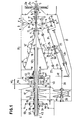
- FIG. 1 the end of the motor shaft 1 is shown, with which the one part 2a of a clutch is connected; the other part 2b of the coupling is connected to a hollow shaft 3.
- the shafts 1 and 3 each have a similar inner profile part 4, with which an outer profile part 5 of a central PTO shaft 6 can optionally be coupled by corresponding axial displacement of this PTO shaft.
- a hollow shift shaft 8 is coupled to the hollow shaft 3 in a longitudinally displaceable manner, but non-rotatably by means of a profile part 7.
- the shift lever 10 mounted at 9, with which the shift shaft can be displaced, engages this shift shaft.
- the forward gear is engaged, which is indicated by the designation V.
- a profile part 11 of the selector shaft 8 is in engagement with the hub of a bevel gear 12, via which a bevel gear 13 and a universal joint 14 an auxiliary shaft 15 is driven in the sense of the forward gear.
- a second profile part 16 of the shift shaft 8 comes into engagement with the hub of a bevel gear 17, while the profile part 11 comes out of engagement with the bevel gear 12.
- the shaft 15 is then driven in the sense of the reverse gear via the bevel gear 17 and the bevel gear 13. In between is a neutral position of the shift lever or the shift shaft 8, designated 0 in FIG. 1, in which position the rotation of the shift shaft 8 is not transmitted to the shaft 15.
- Another position designated D of the shift lever 10 corresponds to a rear extreme position of the shift shaft 8, in which the profile part 11 engages with the front end of a conical step gear set 18 to be described and thus transmits the engine rotation directly to this gear set. For this position, there is also no direct drive from the selector shaft 8 to the auxiliary shaft 15.
- a bevel gear 19 which is axially displaceable but non-rotatable and meshes with a bevel gear 20 on a countershaft 21.
- a spur gear 25 of the countershaft 24 can optionally be coupled to various wheels 18 'of the wheel set 18.
- the shafts 21 and 24 are mounted in a frame 26, which is also indicated in FIG. 2, and which can be pivoted about a pivot axis 27.
- the pivot position of the frame 26 is determined by a knee joint lever, the arms 28 and 29 of which are connected by the joint 30 and of which one pivotally engages the frame 26 and the other pivotally engages the gear housing or gear frame 31 indicated in FIGS. 1 and 2.
- a hydraulic actuating cylinder 33 engages between the toggle joint 30 and a further joint 32 on the frame 26. It serves to buckle the toggle joint 28, 29 during the switching process, as a result of which the frame 26 is pivoted outward about its pivot axis 27 and the gearwheel 25 is disengaged from the gearwheel 18 'of the wheel set 18.
- the countershaft 21 is practically parallel to the surface line of the wheel set 18.
- Another hydraulic actuating cylinder 34 engages the frame 26, which allows this frame to be displaced in the axial direction of the countershaft 21.
- a positioning fork 35 is attached to the frame 26, which can be brought into engagement in various positions with stop cams 36 of a stop shaft 37, which is fixedly arranged in the gear housing 31 and is not shown in FIG 25 clearly in engagement with a gear 18 'of the wheel set 18.
- the countershaft 21 is connected via a cardan shaft 38 to the one shaft 39 of a continuously variable toothed belt transmission.
- the switch positions of the frame 26 or the cylinder 34 are transmitted via a linkage 40 to disks 41 or 42 of the continuously variable toothed belt transmission.
- the transmission ratio of the continuously variable toothed belt transmission is thus automatically adapted to the transmission ratio in the actual manual transmission, that is, between the selector shaft 8 and the gear set 18.
- the wheel set 18 is seated on a hollow shaft 43 which surrounds the PTO shaft 6.
- the vehicle wheels are driven by the hollow shaft 43 via a switchable planetary gear 44, the driven wheel 45 of which is seated on a drive shaft 46, which can be connected to a front and rear wheel drive, as indicated schematically in FIG.
- a sun gear 47 on the shaft 43 of the planetary gear meshes with planet gears 48, which are mounted on the driven gear 49, which meshes with the driven gear 45.
- the planet gears 48 mesh with an outer ring gear 50, which can optionally be coupled to the shaft 43 via an engaged clutch 51 (FIG. 1 above) or to a fixed part 52 when the clutch 51 is disengaged.
- the entire planetary gear rotates at the speed of the shaft 43 and there is a relatively fast, direct drive to the shaft 46. If the ring gear 50 is coupled to the fixed part 52, the planetary gear works as such and transmits the rotation of the Wave 43 with significant reduction to wave 46.
- a further planetary gear 53 is provided, the sun gear 54 of which is seated on a hollow shaft 55 surrounding the shaft 43, on which the pulley 42 and the other pulley of the continuously variable toothed belt transmission associated with it are also seated.
- a coupling piece 57 is longitudinally displaceable but non-rotatable, which can be brought into engagement either with the hollow shaft 55 (position in Figure 1 above) or with the frame 58 of the planetary gear 53 (position in Figure 1 below). It is thus possible to couple the hollow shaft 55 to the hollow shaft 55 either directly or via the strong reduction of the planetary gear 53.
- the new gear is preselected, whereupon the clutch 2 automatically disengages when the clutch 2 is disengaged becomes.
- the cylinder 33 is first actuated, which kinks the toggle levers 28, 29 and thus causes the frame 26 and its axis 24 to pivot outwards.
- the gear 25 is thus disengaged from the gear 18 'of the gear set 18.
- the frame 26 is now unlocked by disengaging it by pivoting the previously effective stop cam 36 of the stop shaft 37 out of the fork 35.
- the frame 26 with the wheels 22, 23 and 25 is now moved along the countershaft 21 by means of the cylinder 34 into the new switching position moved where the fork 35 latches into the newly pivoted cam of the stop shaft 37 and thus precisely determines the position of the frame.
- This displacement of the frame 26 has been transmitted via the linkage 40 to the stepless toothed belt transmission, whereby the transmission ratio thereof has been changed in accordance with the translation of the new selected switching stage.
- the countershaft 21 and the wheels 22, 23 and 25 are now driven via the continuously variable transmission at a synchronized speed.
- the gear 25 can now be reinserted into one of the gears 18 'of the wheel set 18. After this process, the clutch 2 is finally again indented, which restores the flow of power from the engine via the transmission to the drive wheels.
- a direct gear can be selected by switching off the actual gearbox when the gearshift lever is brought into position D, in which case the gearshift shaft 8 is coupled directly to the gear set 18 and via it to the shaft 43. In this position, the reversing gear is switched off and the wheel 25 can preferably be disengaged from the wheel set 18 by controlling the cylinder 33. Furthermore, a third position of the clutch part 57 could be provided in this case, for which the shafts 43 and 55 are uncoupled from one another and consequently also the continuously variable transmission is switched off. All auxiliary parts of the transmission would thus be at a standstill and there would only be a direct drive from the motor shaft to the shaft 43.
- the shift lever can be brought into the zero position, and the PTO shaft 6 can be displaced by means not shown, and can thus be brought into engagement either directly with the motor shaft 1 or via the clutch 2 with the shaft 3.
- the power take-off can be driven directly with the transmission completely stationary, without any gear wheels being in motion.
- the planetary gear 53 allows the engagement of a creeper gear with stepless speed control.
- the gear 25 is disengaged by means of the cylinder 33, and the drive now takes place via the countershaft 21, the continuously variable transmission, the shaft 55, the planetary gear 53 and the coupling piece 57 on the shaft 43, which in turn is switched to the slow gear Planetary gear 44, which drives the vehicle's drive wheels.
- Very low driving speeds can be fine-tuned here.
- the setting of the continuously variable transmission can take place either by means of the switching movements of the cylinder 34 via the linkage 40 or via a special control linkage for the continuously variable transmission.
- One or the other of the planetary gear 44 and 53 can be omitted or can be replaced by another gear.
- a hydraulic clutch can be provided.
- the main transmission can have more or less than seven gear steps. As already mentioned, the main transmission is simple to operate, to set up and to operate. A gearshift lever must be provided which can only be brought into four positions on one level. The switching positions can be preselected separately, and the planetary gears 44 and 53 can also be switched over separately. Likewise, any special control of the continuously variable transmission can take place on a special operating element.
- the countershaft 21 and the cardan shaft 38 are preferably arranged horizontally next to the main axis of the transmission, which results in a low horizontal structure of the transmission. Such a transmission can be made easily accessible, so that it is also particularly favorable in terms of maintenance.
- the simplicity of manufacture results primarily from the dimensional equality of the most expensive parts, in particular the wheel set 18 for a complete type series.
- the gradation of the wheels is chosen, for example, so that there is an opening angle of 18 °. Even with stepped length of the wheel sets, this results in uniform machining per part type across the entire type series with largely the same set-up time programming, the same tool set and the same clamping device. At the same time, there are uniform axis distances, etc., which also facilitates the manufacture of the housing parts of the transmission.
- the planetary gear 44 or a corresponding change-over gear forms a unit together with the direct output to the rear and the front, and no feedback into the actual manual gearbox is necessary.
- the axis distances can be kept uniform for an entire row.
- the fully automatic switching process prevents incorrect operation.
- the process can be carried out very quickly, since there is a force-locking forced synchronization, which ultimately results in a largely uninterrupted flow of power, i. H. particularly short switching times allowed.
- the auxiliary shaft 15 can be arranged such that in the normal operating state according to FIG. 1 it stands radially to the main gear axis and thus exactly in the extension of the shaft of the bevel gear 13.
- the bevel gears 19 and 20 must enclose a correspondingly larger angle than 90 °.
- This solution also presupposes that the gear 20 is axially displaceably seated on the countershaft 21, but the advantage is that any irregularity in the transmission of motion in the normal operating state is eliminated by the universal joint 14.
- the auxiliary shaft 15 only leaves its radial position during the switching process.
Landscapes
- Engineering & Computer Science (AREA)
- General Engineering & Computer Science (AREA)
- Mechanical Engineering (AREA)
- Structure Of Transmissions (AREA)
- Gear-Shifting Mechanisms (AREA)
- Arrangement Or Mounting Of Control Devices For Change-Speed Gearing (AREA)
- Arrangement Of Transmissions (AREA)
- Transmission Devices (AREA)
Description
- Die vorliegende Erfindung betrifft ein Schaltgetriebe an einem Nutzfahrzeug, insbesondere Traktor. Bekannte Getriebe dieser Art sind verhältnismässig umständlich in Aufbau, Bedienung und Wartung, indem beispielsweise abgesehen von einem üblichen Schaltgetriebe noch ein Nachschaltgetriebe vorgesehen ist (Sonderdruck aus «Lastauto/Omnibus », Heft 5/1967). Das Schalten eines solchen Getriebes ist verhältnismässig umständlich. Das Getriebe weist nicht nur einen grossen Aufwand an Einzelteilen auf, sondern die Anzahl von ständig mitlaufenden und somit energieverbrauchenden Zahnrädern ist erheblich, und der für Nutzfahrzeuge wesentliche Zapfwellenantrieb erfolgt in ebenfalls unwirtschaftlicher Weise über die beiden vorhandenen Getriebe. Die Haupt- und Vorgelegewellen der Getriebe sind übereinander angeordnet, was die Wartung erschwert und einen relativ hohen Aufbau und somit hohen Schwerpunkt des Getriebes und des Fahrzeuges ergibt. Die Synchronisation bedingt einen hohen Aufwand an Einzelteilen, Gewicht und Raum.
- Es sind auch Getriebe mit einem starren Satz von Zahnrädern mit abgestuftem Durchmesser bekannt, bei welchen in die Zahnräder ein über eine Vorgelegewelle antreibbares Vorgelegerad wahlweise einrückbar ist (FR-A-380 664). Solche Getriebe sind zwar einfach im Aufbau, lassen jedoch das Problem der für moderne Getriebe geforderten Synchronisation offen.
- Es ist das Ziel vorliegender Erfindung, ausgehend von einem Getriebe der letztgenannten Art, ein Getriebe für Nutzfahrzeuge, insbesondere Traktoren, zu schaffen, welches bei geringem Aufwand eine gute Synchronisation und optimale Antriebsmöglichkeiten bietet. Dieses Ziel wird durch die Massnahmen nach dem Kennzeichen des Anspruchs 1 erreicht. Die Parallelschaltung des Schaltgetriebes und des stufenlos verstellbaren Getriebes erlaubt nicht nur, über den ganzen vielstufigen Schaltbereich die Synchronisation sicherzustellen, sondern über das stufenlose Getriebe kann z. B. im Kriechgang die ganze Antriebsenergie elastisch übertragen und dabei die Geschwindigkeit problemlos geregelt werden. Während des Schaltvorganges kann über das stufenlose Getriebe ein gewisses Restmoment übertragen werden, was nicht nur die Synchronisation bewirkt, sondern die Geschwindigkeit des Fahrzeuges aufrechterhält, bzw. weniger abfallen lässt. Da der Satz von Zahnrädern keine Synchronisationssätze aufweist, kann die diesen Satz tragende Welle als von einer Zentralwelle durchsetzte Hohlwelle ausgeführt sein, ohne dass sich dadurch untragbar grosse Durchmesser für die Getriebeteile ergeben. Ueber die Zentralwelle können Hilfsaggregate, wie z. B. eine Hydraulikpumpe, angetrieben und daher an günstiger Stelle angebracht werden.
- Die Erfindung wird nun anhand eines in der Zeichnung dargestellten Ausführungsbeispiels näher erläutert.
- Figur 1 zeigt ein Gesamtschema des Getriebes,
- Figur 2 zeigt eine schematische Stirnansicht eines Getriebeteils, und
- Figur 3 zeigt eine Positionierungsvorrichtung für den umschaltbaren Getriebeteil.
- In Figur 1 ist das Ende der Motorwelle 1 dargestellt, mit welchem der eine Teil 2a einer Kupplung verbunden ist; der andere Teil 2b der Kupplung ist mit einer Hohlwelle 3 verbunden. Die Wellen 1 und 3 weisen je einen gleichartigen Innenprofilteil 4 auf, mit welchen ein Aussenprofilteil 5 einer zentralen Zapfwelle 6 durch entsprechende Axialverschiebung dieser Zapfwelle wahlweise gekuppelt werden kann. Mit der Hohlwelle 3 ist längsverschiebbar, aber mittels eines Profilteils 7 unverdrehbar eine hohle Schaltwelle 8 gekuppelt. Wie in Figur 1 angedeutet, greift an dieser Schaltwelle der bei 9 gelagerte Schalthebel 10 an, mit welchem die Schaltwelle verschoben werden kann. Bei der dargestellten Stellung des Schalthebels 10, bzw. der Schaltwelle 8 ist der Vorwärtsgang eingeschaltet, was mit der Bezeichnung V angedeutet ist. In diesem Falle steht ein Profilteil 11 der Schaltwelle 8 im Eingriff mit der Nabe eines Kegelrades 12, über welches ein Kegelrad 13 und über ein Kardangelenk 14 eine Hilfswelle 15 im Sinne des Vorwärtsganges angetrieben wird. Wird der Schalthebel 10 in die mit R bezeichnete Rückwärtsstellung verschoben, gelangt ein zweites Profilteil 16 der Schaltwelle 8 in Eingriff mit der Nabe eines Kegelrades 17, während der Profilteil 11 ausser Eingriff mit dem Kegelrad 12 gelangt. Ueber das Kegelrad 17 und das Kegelrad 13 wird dann die Welle 15 im Sinne des Rückwärtsganges angetrieben. Dazwischen befindet sich eine neutrale, in Figur 1 mit 0 bezeichnete Stellung des Schalthebels, bzw. der Schaltwelle 8, in welcher Stellung die Drehung der Schaltwelle 8 nicht auf die Welle 15 übertragen wird. Eine weitere mit D bezeichnete Stellung des Schalthebels 10 entspricht einer hinteren Extremstellung der Schaltwelle 8, in welcher der Profilteil 11 mit dem vorderen Ende eines noch zu beschreibenden kegelförmigen Stufenradsatzes 18 in Eingriff steht und damit die Motordrehung direkt an diesen Radsatz überträgt. Für diese Stellung erfolgt ebenfalls kein direkter Antrieb von der Schaltwelle 8 an die Hilfswelle 15.
- Auf der Hilfswelle 15 sitzt axial verschiebbar aber unverdrehbar ein Kegelrad 19, das mit einem Kegelrad 20 auf einer Vorgelegewelle 21 kämmt. Auf der Vorgelegewelle 21 sitzt axial verschiebbar, aber mit der Vorgelegewelle unverdrehbar gekuppelt, ein Kegelrad 22, das mit einem Kegelrad 23 auf einer weiteren Vorgelegewelle 24 kämmt. Ein Stirnrad 25 der Vorgelegewelle 24 kann wahlweise mit verschiedenen Rädern 18' des Radsatzes 18 gekuppelt werden. Die Wellen 21 und 24 sind in einem Gestell 26 gelagert, das auch in Figur 2 angedeutet ist, und das um eine Schwenkachse 27 geschwenkt werden kann. Die Schwenkstellung des Gestells 26 ist bestimmt durch einen Kniegelenkhebel, dessen Arme 28 und 29 durch das Gelenk 30 verbunden sind und von welchen der eine schwenkbar am Gestell 26 und der andere schwenkbar an dem in den Figuren 1 und 2 angedeuteten Getriebegehäuse oder Getriebegestell 31 angreift. Zwischen dem Kniehebelgelenk 30 und einem weiteren Gelenk 32 am Gestell 26 greift ein hydraulischer Betätigungszylinder 33 an. Er dient dazu, beim Schaltvorgang das Kniehebelgelenk 28, 29 einzuknicken, wodurch das Gestell 26 um seine Schwenkachse 27 nach aussen geschwenkt und das Zahnrad 25 aus dem Zahnrad 18' des Radsatzes 18 ausgerückt wird. Die Vorgelegewelle 21 steht praktisch parallel zur Mantellinie des Radsatzes 18. Am Gestell 26 greift ein weiterer hydraulischer Betätigungszylinder 34 an, welcher dieses Gestell in Achsrichtung der Vorgelegewelle 21 zu verschieben gestattet. Am Gestell 26 ist gemäss Figur 3 eine Positionierungsgabel 35 angebracht, welche in verschiedenen Positionen mit Anschlagnocken 36 einer fest im Getriebegehäuse 31 angeordneten, in Figur 1 nicht dargestellten Anschlagwelle 37 in Eingriff gebracht werden kann, um die Schaltstellung des Gestells 26, bzw. des Zahnrads 25 im Eingriff mit einem Zahnrad 18' des Radsatzes 18 eindeutig zu bestimmen.
- Die Vorgelegewelle 21 ist über eine Kardanwelle 38 mit der einen Welle 39 eines stufenlosen Zahnriemengetriebes verbunden. Die Schaltstellungen des Gestells 26, bzw. des Zylinders 34 werden über ein Gestänge 40 auf Scheiben 41, bzw. 42 des stufenlosen Zahnriemengetriebes übertragen. Das Uebersetzungsverhältnis des stufenlosen Zahnriemengetriebes wird damit jeweils automatisch dem Uebersetzungsverhältnis im eigentlichen Schaltgetriebe, also zwischen der Schaltwelle 8 und dem Radsatz 18, angepasst.
- Der Radsatz 18 sitzt auf einer Hohlwelle 43, welche die Zapfwelle 6 umgibt. Von der Hohlwelle 43 erfolgt der Antrieb der Fahrzeugräder über ein umschaltbares Planetengetriebe 44, dessen Abtriebsrad 45 auf einer Antriebswelle 46 sitzt, die mit einem Vorder- und Hinterradantrieb in Verbindung stehen kann, wie in Figur 1 schematisch angedeutet ist. Ein auf der Welle 43 sitzendes Sonnenrad 47 des Planetengetriebes kämmt mit Planetenrädern 48, welche auf dem Abtriebsrad 49 gelagert sind, welches mit dem Abtriebsrad 45 kämmt. Die Planetenräder 48 kämmen mit einem äusseren Zahnkranz 50, welcher wahlweise über eine eingerückte Kupplung 51 (Figur 1 oben) mit der Welle 43 oder bei ausgerückter Kupplung 51 mit einem festen Teil 52 gekuppelt werden kann. Im ersten Falle läuft das ganze Planetengetriebe mit der Geschwindigkeit der Welle 43 um, und es erfolgt ein verhältnismässig schneller, direkter Antrieb auf die Welle 46. Ist der Zahnkranz 50 mit dem festen Teil 52 gekuppelt, arbeitet das Planetengetriebe als solches und überträgt die Drehung der Welle 43 mit erheblicher Untersetzung an die Welle 46.
- Es ist ein weiteres Planetengetriebe 53 vorgesehen, dessen Sonnenrad 54 auf einer, die Welle 43 umgebenden Hohlwelle 55 sitzt, auf welcher auch die Scheibe 42 und die ihr zugeordnete andere Scheibe des stufenlosen Zahnriemengetriebes sitzen. Auf der Welle 43 sitzt ein Kupplungsstück 57 längsverschiebbar, aber unverdrehbar, das wahlweise entweder mit der Hohlwelle 55 (Stellung in Figur 1 oben) oder mit dem Gestell 58 des Planetengetriebes 53 (Stellung in Figur 1 unten) in Eingriff gebracht werden kann. Es ist damit möglich, die Hohlwelle 55 wahlweise direkt oder über die starke Untersetzung des Planetengetriebes 53 mit der Hohlwelle 55 zu kuppeln.
- Die Arbeitsweise und Bedienung des Getriebes ergibt sich weitgehend aus der Darstellung und vorstehenden Beschreibung. Bei der dargestellten normalen Stellung des Getriebes erfolgt der Kraftfluss von der Motorwelle 1, die Kupplung 2, die Welle 3, die Schaltwelle 8, die Räder 12 und 13, das Kardangelenk 14, die Hilfswelle 15, die Vorgelegewelle 21, die Räder 22, 23, 25 und den Radsatz 18, die Welle 43 und das Planetengetriebe 44 an die Antriebswelle 46 für die Räder des Fahrzeugs. Durch Umschalten des Planetengetriebes 44 in der beschriebenen Weise können wahlweise schnelle und langsame Gänge eingeschaltet werden. Für jeden Bereich stehen sieben Gänge entsprechend den sieben Rädern 18' des Radsatzes 18 zur Verfügung. Normalerweise ist die Welle 55 mit der Welle 43 gekuppelt und das Uebersetzungsverhältnis des stufenlosen Zahnriemengetriebes entspricht genau dem Uebersetzungsverhältnis zwischen der Vorgelegewelle 21 und dem Radsatz 18. Zum Schalten in einen anderen Gang wird der neue Gang vorgewählt worauf beim Ausrücken der Kupplung 2 der Schaltvorgang automatisch ausgelöst wird. Hierbei wird zuerst der Zylinder 33 betätigt, welcher die Kniehebel 28, 29 einknickt und damit eine Verschwenkung des Gestelles 26 und seine Achse 24 nach aussen bewirkt. Damit wird das Zahnrad 25 aus dem Zahnrad 18' des Radsatzes 18 ausgerückt. Es erfolgt nun die Entriegelung des Gestells 26 durch Ausrücken durch Verschwenken des bisher wirksamen Anschlagnockens 36 der Anschlagwelle 37 aus der Gabel 35. Das Gestell 26 mit den Rädern 22, 23 und 25 wird nun längs der Vorgelegewelle 21 mittels des Zylinders 34 in die neue Schaltstellung verschoben, wo die Gabel 35 in den neu in wirksame Stellung verschwenkten Nocken der Anschlagwelle 37 einklinkt und damit die Stellung des Gestells genau bestimmt. Diese Verschiebung des Gestells 26 ist über das Gestänge 40 auf das stufenlose Zahnriemengetriebe übertragen worden, womit das Uebersetzungsverhältnis desselben der Uebersetzung der neuen gewählten Schaltstufe entsprechend verändert worden ist. Die Vorgelegewelle 21 und die Räder 22, 23 und 25 werden also nun über das stufenlose Getriebe mit synchronisierter Drehzahl angetrieben. Es kann nun das Wiedereinrücken des Zahnrades 25 in eines der Zahnräder 18' des Radsatzes 18 erfolgen. Nach diesem Vorgang wird schliesslich auch die Kupplung 2 wieder eingerückt, womit der Kraftfluss vom Motor über das Getriebe zu den Triebrädern wieder hergestellt ist.
- Wie bereits erwähnt, kann unter Ausschaltung des eigentlichen Schaltgetriebes ein Direktgang gewählt werden, wenn der Schalthebel in die Stellung D gebracht wird, in welchem Falle die Schaltwelle 8 direkt mit dem Radsatz 18 und über denselben mit der Welle 43 gekuppelt ist. In dieser Stellung ist das Reversiergetriebe ausgeschaltet und es kann vorzugsweise durch Steuerung des Zylinders 33 auch das Rad 25 aus dem Radsatz 18 ausgekuppelt sein. Ferner könnte in diesem Falle eine dritte Stellung des Kupplungsteils 57 vorgesehen sein, für welche die Wellen 43 und 55 voneinander entkuppelt sind und demzufolge auch das stufenlose Getriebe ausgeschaltet ist. Es würden somit alle Hilfsteile des Getriebes stillstehen, und es würde nur ein direkter Antrieb von der Motorwelle zur Welle 43 erfolgen.
- Anderseits kann der Schalthebel in die Nullstellung gebracht werden, und durch nichtdargestellte Mittel kann die Zapfwelle 6 verschoben und damit entweder direkt mit der Motorwelle 1 oder aber über die Kupplung 2 mit der Welle 3 in Eingriff gebracht werden. Es kann in diesem Falle bei völlig stillstehendem Getriebe ein direkter Antrieb der Zapfwelle erfolgen, ohne dass irgendwelche Getrieberäder in Bewegung wären.
- Das Planetengetriebe 53 gestattet die Einschaltung eines Kriechganges mit stufenloser Geschwindigkeitsregelung. In dieser Stellung wird das Zahnrad 25 mittels des Zylinders 33 ausgerückt, und der Antrieb erfolgt nun über die Vorgelegwelle 21, das stufenlose Getriebe, die Welle 55, das Planetengetriebe 53 und das Kupplungsstück 57 auf die Welle 43, welche ihrerseits über das auf Langsamgang geschaltete Planetengetriebe 44, die Triebräder des Fahrzeugs, antreibt. Es können hierbei sehr niedrige Fahrgeschwindigkeiten fein eingestellt werden. Die Einstellung des stufenlosen Getriebes kann hierbei entweder mittels der Schaltbewegungen des Zylinders 34 über das Gestänge 40 oder über ein besonderes Steuergestänge für das stufenlose Getriebe erfolgen.
- Es sind verschiedene Ausführungsvarianten möglich. Das eine oder andere der Planetengetriebe 44 und 53 kann wegfallen oder kann durch ein anderes Getriebe ersetzt werden. Es kann eine hydraulische Kupplung vorgesehen sein. Das Hauptgetriebe kann mehr oder meniger als sieben Schaltstufen aufweisen. Das Hauptgetriebe ist, wie bereits erwähnt, einfach in der Bedienung, im Aufbau und in der Arbeitsweise. Es ist ein Schalthebel vorzusehen, der nur in einer Ebene in vier Stellungen zu bringen ist. Die Schaltstellungen können gesondert vorgewählt werden, und die Umschaltung der Planetengetriebe 44 und 53 kann auch separat erfolgen. Desgleichen kann eine eventuelle besondere Steuerung des stufenlosen Getriebes an einem besonderen Bedienungselement erfolgen. Die Vorgelegewelle 21 sowie die Kardanwelle 38 werden vorzugsweise horizontal neben der Hauptachse des Getriebes angeordnet, was einen niedrigen horizontalen Aufbau des Getriebes ergibt. Ein solches Getriebe kann leicht zugänglich gemacht werden, so dass es auch besonders günstig hinsichtlich Wartung ist.
- Zusammenfassend seien weitere Vorteile erwähnt, die sich aus der beschriebenen Getriebekonstruktion ergeben.
- Die Einfachheit der Herstellung ergibt sich vorwiegend aus der Massgleichheit der teuersten Teile, insbesondere des Radsatzes 18 für eine vollständige Typenreihe. Die Abstufung der Räder ist beispielsweise so gewählt, dass sich ein Oeffnungswin kel von 18° ergibt. Auch bei abgestufter Länge der Radsätze ergibt sich somit eine einheitliche Bearbeitung pro Teiltyp über die ganze Typenreihe mit weitgehend gleicher Rüstzeitprogrammierung, demselben Werkzeugsatz und derselben Ausspannvorrichtung. Zugleich ergeben sich einheitliche Achsdistanzen, usw., was auch die Herstellung der Gehäuseteile des Getriebes erleichtert.
- Bei der dargestellten Ausführung bildet das Planetengetriebe 44, bzw. ein entsprechendes Umschaltgetriebe zusammen mit dem direkten Abtrieb nach hinten und vorne eine Einheit, und es ist keine Rückführung in das eigentliche Schaltgetriebe nötig. Auch hier können die Achsdistanzen für eine gesamte Reihe einheitlich gehalten werden.
- Die direkte Durchführung der Zapfwelle 6 und die Möglichkeit der vollständigen Stillegung des übrigen Getriebes erlaubt einen besonders wirtschaftlichen Betrieb.
- Durch die Anordnung des Reversiergetriebes am Eingang können alle möglichen Uebersetzungsverhältnisse für Vorwärts- und Rückwärtsfahrt ausgenützt werden.
- Der vollautomatische Schaltvorgang schliesst Falschbedienungen aus. Der Vorgang kann sehr schnell erfolgen, da eine kraftschlüssige Zwangssynchronisierung vorliegt, was schliesslich einen weitgehend unterbruchlosen Kraftfluss, d. h. besonders kurze Schaltzeiten erlaubt.
- Um eine möglichst gleichförmige Bewegungsübertragung während des normalen Betriebs zu erzielen, kann die Hilfswelle 15 so angeordnet werden, dass sie im normalen Betriebszustand nach Fig. 1 zur Hauptgetriebeachse radial und somit genau in der Verlängerung der Welle des Kegelrades 13 steht. Die Kegelräder 19 und 20 müssen in diesem Falle einen entsprechend grösseren Winkel als 90° einschliessen. Diese Lösung setzt überdies voraus, dass das Zahnrad 20 axial verschiebbar auf der Vorgelegewelle 21 sitzt, aber der Vorteil liegt darin, dass jede Ungleichförmigkeit der Bewegungsübertragung in normalen Betriebszustand durch das Kardangelenk 14 ausgeschlossen wird. Die Hilfswelle 15 verlässt ihre radiale Lage nur während des Schaltvorgangs.
Claims (10)
Priority Applications (1)
| Application Number | Priority Date | Filing Date | Title |
|---|---|---|---|
| AT81810220T ATE9030T1 (de) | 1980-06-06 | 1981-06-05 | Schaltgetriebe an einem nutzfahrzeug. |
Applications Claiming Priority (2)
| Application Number | Priority Date | Filing Date | Title |
|---|---|---|---|
| CH4375/80A CH654083A5 (de) | 1980-06-06 | 1980-06-06 | Schaltgetriebe an einem nutzfahrzeug. |
| CH4375/80 | 1980-06-06 |
Publications (3)
| Publication Number | Publication Date |
|---|---|
| EP0041925A2 EP0041925A2 (de) | 1981-12-16 |
| EP0041925A3 EP0041925A3 (en) | 1982-06-09 |
| EP0041925B1 true EP0041925B1 (de) | 1984-08-15 |
Family
ID=4274935
Family Applications (1)
| Application Number | Title | Priority Date | Filing Date |
|---|---|---|---|
| EP81810220A Expired EP0041925B1 (de) | 1980-06-06 | 1981-06-05 | Schaltgetriebe an einem Nutzfahrzeug |
Country Status (4)
| Country | Link |
|---|---|
| EP (1) | EP0041925B1 (de) |
| AT (1) | ATE9030T1 (de) |
| CH (1) | CH654083A5 (de) |
| DE (1) | DE3165548D1 (de) |
Families Citing this family (8)
| Publication number | Priority date | Publication date | Assignee | Title |
|---|---|---|---|---|
| FR2678696A1 (fr) * | 1991-07-04 | 1993-01-08 | Renault | Boite de vitesses a variation continue entre deux rapports discrets. |
| IT1250494B (it) * | 1991-07-11 | 1995-04-08 | Luigi Celani | Variatore continuo di velocita' a rapporti fissi, meccanico con ruote dentate cilindriche a denti elicoidali, capace di cambiare rapporto senza richiedere interruzioni nella erogazione della potenza, scollegamenti, ausilio di sincronizzatori, freni o frizioni |
| DE10151752A1 (de) * | 2001-10-19 | 2003-05-08 | Zahnradfabrik Friedrichshafen | Schaltgetriebe in Vorgelegewellenbauweise |
| US7461570B2 (en) * | 2006-07-06 | 2008-12-09 | Mothaffar Hussain Y | Variable transmission using frusto-conical gears and sliding face gears |
| US8127636B2 (en) * | 2006-07-06 | 2012-03-06 | Mothaffar Hussain Y | Variable transmission for a motor vehicle |
| US8883146B2 (en) | 2007-11-30 | 2014-11-11 | Abbvie Inc. | Protein formulations and methods of making same |
| JP2013064511A (ja) * | 2013-01-06 | 2013-04-11 | Hideki Matsumura | 歯車式無段変速機構 |
| CN112173136B (zh) * | 2020-09-25 | 2023-07-25 | 中国直升机设计研究所 | 一种直升机用的发动机机械油门操作系统 |
Family Cites Families (11)
| Publication number | Priority date | Publication date | Assignee | Title |
|---|---|---|---|---|
| DE186422C (de) * | 1906-07-18 | 1907-04-20 | ||
| FR380664A (fr) * | 1907-07-20 | 1907-12-14 | Richard Matthews Ruck | Mécanisme de changement de vitesse |
| US1338974A (en) * | 1918-08-23 | 1920-05-04 | Davisbournonville Company | Change-speed gearing |
| US1471162A (en) * | 1920-10-11 | 1923-10-16 | Iacobacci Domenico | Multiple-speed drive mechanism |
| US1453478A (en) * | 1921-04-25 | 1923-05-01 | Alden E Osborn | Cone-gear transmission mechanism |
| GB216544A (en) * | 1923-01-01 | 1924-06-02 | Edgar Fairweather | Improvements in variable speed toothed wheel gearing |
| US1528574A (en) * | 1924-07-03 | 1925-03-03 | Schaum Louis | Variable-speed-transmission mechanism |
| CH111842A (fr) * | 1924-10-07 | 1925-09-16 | Reid Wylie Robert William | Dispositif de changement de vitesse. |
| US1817819A (en) * | 1929-04-11 | 1931-08-04 | Healey Francis Jeremiah | Variable velocity ratio gearing |
| US3702571A (en) * | 1971-09-17 | 1972-11-14 | Jorge R Sainz | Variable speed transmission |
| EP0004412A1 (de) * | 1978-01-21 | 1979-10-03 | GKN Transmissions Limited | Stufenlos regelbares Getriebe |
-
1980
- 1980-06-06 CH CH4375/80A patent/CH654083A5/de not_active IP Right Cessation
-
1981
- 1981-06-05 AT AT81810220T patent/ATE9030T1/de not_active IP Right Cessation
- 1981-06-05 EP EP81810220A patent/EP0041925B1/de not_active Expired
- 1981-06-05 DE DE8181810220T patent/DE3165548D1/de not_active Expired
Also Published As
| Publication number | Publication date |
|---|---|
| EP0041925A3 (en) | 1982-06-09 |
| CH654083A5 (de) | 1986-01-31 |
| ATE9030T1 (de) | 1984-09-15 |
| DE3165548D1 (en) | 1984-09-20 |
| EP0041925A2 (de) | 1981-12-16 |
Similar Documents
| Publication | Publication Date | Title |
|---|---|---|
| EP0262625B1 (de) | Verfahren zum Schalten eines aus mehreren Getriebeeinheiten bestehenden Getriebes | |
| EP0128319B1 (de) | Wechselgetriebe mit synchronisiertem Rückwärtsgang | |
| DE4400701C2 (de) | Übertragungsvorrichtung zur Übertragung einer Motorleistung auf Antriebsräder eines Fahrzeuges | |
| DE2328218C3 (de) | Schaltvorrichtung für ein Wechselgetriebe | |
| DE102006054363A1 (de) | Lastschaltgetriebe | |
| DE3021254A1 (de) | Zapfwellenantriebseinrichtung fuer einen ackerschlepper | |
| DE2639000A1 (de) | Mechanisches mehrganggetriebe fuer fahrzeuge | |
| DE4443267A1 (de) | Lastschaltgetriebe mit 5-welligem Umlaufgetriebe | |
| DE19529312A1 (de) | Getriebebaugruppe für Zugmaschinen | |
| DE60220745T2 (de) | Getriebe mit parallelen Wellen und Verfahren zur Steuerung der Schaltungen | |
| DE3233931C2 (de) | ||
| DE2930950C2 (de) | Fahrzeugwechselgetriebe, insbesondere für Ackerschlepper | |
| DE2819220C2 (de) | Traktor-Getriebeanordnung | |
| EP0041925B1 (de) | Schaltgetriebe an einem Nutzfahrzeug | |
| DE1530614C3 (de) | Zahnräderwechselgetriebe in Gruppenbauart für Ackerschlepper | |
| EP0105124B1 (de) | Zahnräderwechselgetriebe in Gruppenbauweise | |
| DE2110434B2 (de) | Zahnräderwechselgetriebe in Gruppenbauart für Kraftfahrzeuge mit einem Zentralrohrrahmen und insbesondere mit einem Mehrachsantrieb | |
| DE2065300C3 (de) | Schaltvorrichtung für ein vorzugsweise in Gruppenbauart ausgeführtes Zahnräderwechselgetriebe für Fahrzeuge | |
| DE2405700B2 (de) | Getriebe für Motorfahrzeuge | |
| EP0353698B1 (de) | Antrieb für Kraftfahrzeuge | |
| DE1113621B (de) | Umlaufraedergetriebe mit Leistungsverzweigung in mechanische und hydrostatische Zweige | |
| DE644947C (de) | Zahnraederwechselgetriebe, insbesondere fuer Kraftfahrzeuge | |
| DE102020201775B3 (de) | Leistungsverzweigtes stufenloses Getriebe | |
| DE2410163C2 (de) | Zahnräderwechselgetriebe in Gruppenbauweise, insbesondere für land- und/oder bauwirtschaftlich nutzbare Kraftfahrzeuge | |
| DE1580104C (de) | Stufenlos einstellbares Gruppengetriebe für Fahrzeuge |
Legal Events
| Date | Code | Title | Description |
|---|---|---|---|
| PUAI | Public reference made under article 153(3) epc to a published international application that has entered the european phase |
Free format text: ORIGINAL CODE: 0009012 |
|
| AK | Designated contracting states |
Designated state(s): AT BE DE FR GB IT LU NL SE |
|
| PUAL | Search report despatched |
Free format text: ORIGINAL CODE: 0009013 |
|
| AK | Designated contracting states |
Designated state(s): AT BE DE FR GB IT LU NL SE |
|
| 17P | Request for examination filed |
Effective date: 19821208 |
|
| ITF | It: translation for a ep patent filed | ||
| GRAA | (expected) grant |
Free format text: ORIGINAL CODE: 0009210 |
|
| AK | Designated contracting states |
Designated state(s): AT BE DE FR GB IT LU NL SE |
|
| REF | Corresponds to: |
Ref document number: 9030 Country of ref document: AT Date of ref document: 19840915 Kind code of ref document: T |
|
| REF | Corresponds to: |
Ref document number: 3165548 Country of ref document: DE Date of ref document: 19840920 |
|
| ET | Fr: translation filed | ||
| PLBE | No opposition filed within time limit |
Free format text: ORIGINAL CODE: 0009261 |
|
| STAA | Information on the status of an ep patent application or granted ep patent |
Free format text: STATUS: NO OPPOSITION FILED WITHIN TIME LIMIT |
|
| PG25 | Lapsed in a contracting state [announced via postgrant information from national office to epo] |
Ref country code: LU Free format text: LAPSE BECAUSE OF NON-PAYMENT OF DUE FEES Effective date: 19850630 |
|
| 26N | No opposition filed | ||
| PGFP | Annual fee paid to national office [announced via postgrant information from national office to epo] |
Ref country code: AT Payment date: 19860630 Year of fee payment: 6 |
|
| PGFP | Annual fee paid to national office [announced via postgrant information from national office to epo] |
Ref country code: NL Payment date: 19870630 Year of fee payment: 7 |
|
| PG25 | Lapsed in a contracting state [announced via postgrant information from national office to epo] |
Ref country code: GB Effective date: 19880605 |
|
| PG25 | Lapsed in a contracting state [announced via postgrant information from national office to epo] |
Ref country code: NL Effective date: 19890101 |
|
| NLV4 | Nl: lapsed or anulled due to non-payment of the annual fee | ||
| GBPC | Gb: european patent ceased through non-payment of renewal fee | ||
| PG25 | Lapsed in a contracting state [announced via postgrant information from national office to epo] |
Ref country code: AT Effective date: 19890605 |
|
| PG25 | Lapsed in a contracting state [announced via postgrant information from national office to epo] |
Ref country code: SE Effective date: 19890606 |
|
| PG25 | Lapsed in a contracting state [announced via postgrant information from national office to epo] |
Ref country code: BE Effective date: 19890630 |
|
| BERE | Be: lapsed |
Owner name: WUTHRICH HANSRUDOLF Effective date: 19890630 |
|
| PG25 | Lapsed in a contracting state [announced via postgrant information from national office to epo] |
Ref country code: FR Free format text: LAPSE BECAUSE OF NON-PAYMENT OF DUE FEES Effective date: 19900228 |
|
| PG25 | Lapsed in a contracting state [announced via postgrant information from national office to epo] |
Ref country code: DE Effective date: 19900301 |
|
| REG | Reference to a national code |
Ref country code: FR Ref legal event code: ST |
|
| EUG | Se: european patent has lapsed |
Ref document number: 81810220.4 Effective date: 19900412 |