EP0041902B1 - Procédé et dispositif pour établir des communications bidirectionnelles et/ou multidirectionnelles entre différentes personnes regroupées en différentes stations géographiquement éloignées et reliées entre elles par des lignes téléphoniques - Google Patents
Procédé et dispositif pour établir des communications bidirectionnelles et/ou multidirectionnelles entre différentes personnes regroupées en différentes stations géographiquement éloignées et reliées entre elles par des lignes téléphoniques Download PDFInfo
- Publication number
- EP0041902B1 EP0041902B1 EP81400921A EP81400921A EP0041902B1 EP 0041902 B1 EP0041902 B1 EP 0041902B1 EP 81400921 A EP81400921 A EP 81400921A EP 81400921 A EP81400921 A EP 81400921A EP 0041902 B1 EP0041902 B1 EP 0041902B1
- Authority
- EP
- European Patent Office
- Prior art keywords
- station
- conference
- person
- stations
- network
- Prior art date
- Legal status (The legal status is an assumption and is not a legal conclusion. Google has not performed a legal analysis and makes no representation as to the accuracy of the status listed.)
- Expired
Links
- 238000000034 method Methods 0.000 title claims description 46
- 230000007176 multidirectional communication Effects 0.000 title claims description 9
- 230000007175 bidirectional communication Effects 0.000 title description 8
- 230000006854 communication Effects 0.000 claims description 98
- 238000004891 communication Methods 0.000 claims description 98
- 230000005540 biological transmission Effects 0.000 claims description 34
- 230000002457 bidirectional effect Effects 0.000 claims description 15
- 239000003999 initiator Substances 0.000 claims description 15
- 238000010200 validation analysis Methods 0.000 claims description 11
- 239000002775 capsule Substances 0.000 claims description 10
- 238000012545 processing Methods 0.000 claims description 5
- 230000000694 effects Effects 0.000 claims description 4
- 230000011664 signaling Effects 0.000 claims description 3
- 239000003086 colorant Substances 0.000 claims 1
- 230000003247 decreasing effect Effects 0.000 claims 1
- 238000001514 detection method Methods 0.000 claims 1
- 230000004044 response Effects 0.000 description 7
- 230000006870 function Effects 0.000 description 6
- 238000006677 Appel reaction Methods 0.000 description 4
- 238000012546 transfer Methods 0.000 description 4
- 238000010586 diagram Methods 0.000 description 3
- 230000000295 complement effect Effects 0.000 description 1
- 239000004020 conductor Substances 0.000 description 1
- 239000000470 constituent Substances 0.000 description 1
- 238000012217 deletion Methods 0.000 description 1
- 230000037430 deletion Effects 0.000 description 1
- 230000001627 detrimental effect Effects 0.000 description 1
- 235000021183 entrée Nutrition 0.000 description 1
- 230000003203 everyday effect Effects 0.000 description 1
- 238000005286 illumination Methods 0.000 description 1
- 230000004807 localization Effects 0.000 description 1
- 230000000284 resting effect Effects 0.000 description 1
- 230000008054 signal transmission Effects 0.000 description 1
- 230000001755 vocal effect Effects 0.000 description 1
Images

Classifications
-
- H—ELECTRICITY
- H04—ELECTRIC COMMUNICATION TECHNIQUE
- H04M—TELEPHONIC COMMUNICATION
- H04M3/00—Automatic or semi-automatic exchanges
- H04M3/42—Systems providing special services or facilities to subscribers
- H04M3/56—Arrangements for connecting several subscribers to a common circuit, i.e. affording conference facilities
- H04M3/563—User guidance or feature selection
- H04M3/566—User guidance or feature selection relating to a participants right to speak
-
- H—ELECTRICITY
- H04—ELECTRIC COMMUNICATION TECHNIQUE
- H04M—TELEPHONIC COMMUNICATION
- H04M3/00—Automatic or semi-automatic exchanges
- H04M3/42—Systems providing special services or facilities to subscribers
- H04M3/56—Arrangements for connecting several subscribers to a common circuit, i.e. affording conference facilities
-
- H—ELECTRICITY
- H04—ELECTRIC COMMUNICATION TECHNIQUE
- H04M—TELEPHONIC COMMUNICATION
- H04M2201/00—Electronic components, circuits, software, systems or apparatus used in telephone systems
- H04M2201/38—Displays
-
- H—ELECTRICITY
- H04—ELECTRIC COMMUNICATION TECHNIQUE
- H04M—TELEPHONIC COMMUNICATION
- H04M3/00—Automatic or semi-automatic exchanges
- H04M3/42—Systems providing special services or facilities to subscribers
- H04M3/56—Arrangements for connecting several subscribers to a common circuit, i.e. affording conference facilities
- H04M3/567—Multimedia conference systems
-
- Y—GENERAL TAGGING OF NEW TECHNOLOGICAL DEVELOPMENTS; GENERAL TAGGING OF CROSS-SECTIONAL TECHNOLOGIES SPANNING OVER SEVERAL SECTIONS OF THE IPC; TECHNICAL SUBJECTS COVERED BY FORMER USPC CROSS-REFERENCE ART COLLECTIONS [XRACs] AND DIGESTS
- Y10—TECHNICAL SUBJECTS COVERED BY FORMER USPC
- Y10S—TECHNICAL SUBJECTS COVERED BY FORMER USPC CROSS-REFERENCE ART COLLECTIONS [XRACs] AND DIGESTS
- Y10S379/00—Telephonic communications
- Y10S379/908—Multimedia
Definitions
- the invention generally relates to communication techniques for exchanging information between different people, and more particularly relates to a method and a device for establishing bidirectional and / or multidirectional communications between different people grouped together in different geographically distant stations and linked together by telephone lines such as specialized links, to allow in particular the setting up and carrying out of remote conferences.
- French patent application no. 2 390 864 discloses an audio conference system by telephone link between at least two groups of distant speakers, each group taking place around a conference table centrally comprising an acoustic speaker and microphones distributed around the 'acoustic enclosure and being associated with a transmission part and a reception part of the signals transmitted by the telephone link, the system also comprising a display panel with indicators for identifying speakers of distant premises.
- the invention aims to overcome in particular the above drawbacks and proposes simple solutions guaranteeing any reliability and consistency in the exchange of information.
- the method according to the invention it is possible to have sent at any time, during the course of the conference and by a station participating in this conference, a coded signal for request for intervention from a person of this station, to view this request for intervention on the display unit of the other stations participating in the conference, and to give the floor to this person on the order of the initiator of the conference for example, this coded signal identifying the name of that person.
- the method according to the invention it is possible, at any time during the course of the conference, to have sent by a station not invited to the conference, a coded signal for intervention request from a person from this station, to view this request for intervention on the af unit the stations participating in the conference, and to invite said person to participate in the conference only on the order of the conference initiator, the microphone of the requesting station being switched off until the station has received a validation signal enabling the microphone to be switched on, in order to avoid any untimely entry of people into the network which could disturb the conference.
- the different stations capable of participating in a conference are linked by dedicated links, in particular by forming a star network comprising a central station connected to the other stations by a dedicated link, two stations can be connected together by a telephone line of the switched network.
- all the stations constituting a communication network are materialized at each station by a synoptic table schematically reproducing the geographical limits of the network and locating the location of the different stations of this network, each localization being materialized for example by two light-emitting diodes of different color and lit in a flashing or fixed way according to the state of each station during the conference, and thus allowing any person of a station to quickly take note and d 'a single glance at the stations concerned by a conference, the state of each station in the conference, and any requests for intervention from stations belonging to the network and asking to join the conference.
- a person not present in a station of a network can, thanks in particular to a portable transmission unit, connect to a station of the network by a telephone line of the switched network, to participate in a conference possibly set up at its instigation between several stations of this network.
- the invention also relates to a device for establishing bidirectional and / or multidirectional communications for example of the telephone type and / or for exchanging information for example in the form of data or telephone messages according to the method of the invention, characterized in what it includes a notably conventional telephone set which includes at least one alpha-numeric keyboard, a display unit and a set of processing circuits essentially consisting of a microprocessor comprising a central unit, a memory unit in which are recorded personalized information constituting a directory, a programmable read-only memory comprising at least one recorded program making it possible to ensure the various automatic sequences of search and launching of a telephone call, and an interface circuit mounted between said microprocessor, the keyboard alpha-numeric and display unit as well as a switching circuit tion connected to the telephone set and the telephone line and in that it further comprises a second memory unit for recording the aforementioned personalized information of a correspondent found in the aforementioned directory, but whose call sequence translated by a line busy signal, in order to make again and automatically, after
- Another object of the invention is a device for establishing bidirectional and / or multidirectional communications, for example of the telephone type and / or for exchanging information, for example in the form of data or telephone messages, between different people grouped together in different stations geographically. distant and linked together by telephone lines, each station of a network comprising an apparatus comprising at least one transmitting unit equipped with a microphone, a receiving unit equipped with a loudspeaker and a display unit with light-emitting diodes, characterized in that each station also includes a unit forming a reader of an individual information medium such as a badge on which is recorded the name of the person holding the badge to register the name of this person on the business unit chage of each station entered into the conference when it intervenes, and an interface unit connecting these different units to a telephone line, this apparatus being located at each station of a communication network comprising several stations linked together by telephone lines and in particular by specialized links.
- an individual information medium such as a badge on which is recorded the name of the person holding the badge to register the name
- the apparatus located at a station may also include a synoptic table schematically reproducing the geographical limits of a network grouping together several stations of this network, each station being materialized by means capable of emitting light such as light-emitting diodes, the light state of which indicates, at any time, the state of this station during a conference, these means being controlled automatically and / or manually according to the progress of the conference.
- a synoptic table schematically reproducing the geographical limits of a network grouping together several stations of this network, each station being materialized by means capable of emitting light such as light-emitting diodes, the light state of which indicates, at any time, the state of this station during a conference, these means being controlled automatically and / or manually according to the progress of the conference.
- a person not present in a station of a communication network can have a special apparatus capable of being connected, by a telephone line of the switched network, to a station of a network, this special apparatus consisting of at least one transmitting unit, a receiving unit, a badge reader, and an interface circuit to which the handset of a conventional telephone set is connected, for example.
- the number of participants in a conference is not limiting, these people being able to be located within the same station in different premises, each room being equipped with an apparatus conforming to the invention and locally connected to other equipment of the station.
- the requests for intervention during a conference are displayed at each station of the network, which makes it possible to ensure a better running of the conference.
- a communication network includes at least two stations ST1, ST2 linked together by a telephone line 2 of the switched network and an auto-switch 3.
- the equipment of a station ST1, ST2 comprises at least one communication unit U such as that shown in fig. 2, this same communication unit being referenced U1 for the station ST1 and U2 for the station ST2.
- the communication unit U also includes a reader unit 15 of a recording medium 16 such as a badge which, for reading, is inserted into a slot 17 of the unit U (FIG. 2).
- a reader unit 15 of a recording medium 16 such as a badge which, for reading, is inserted into a slot 17 of the unit U (FIG. 2).
- This badge 16 are recorded, magnetically for example, coded information personalizing a person and in particular the name of the person to whom this badge is assigned.
- This reader 15 is connected by unidirectional links L7 to the display lines 7a, 7b and to the telephone line 14 via the switching and control circuit 12.
- the switch 11 shown diagrammatically in FIG. 3 by a simple switch, is connected by bidirectional links L8 to the reader 15 and to the switching and control device 12, so as to be able to automatically control the transfer of the name of the person recorded on his badge 16 to the telephone line 14, when this person requests an intervention.
- the communication unit U can advantageously be connected, by bidirectional links L9, to a recording unit 20, a printer unit 21, and to a computer unit 22 to allow additional operations.
- the recording unit 20 makes it possible in particular to record on a magnetic medium messages transmitted to the communication unit U with simultaneous printing or not on the printer unit 21, while the computer unit 22 can allow the consultation of files possibly during a conference.
- These auxiliary units 20, 21, 22 are connected on the one hand to the control and switching circuit 12 ensuring the connection with the telephone line 14 and on the other hand, with the keyboards 4, 5 for example to control these auxiliary units, by L9 links.
- a communication unit U also includes three indicators V1, V2, V3 located near the display unit 7 and whose functions will be explained below. These indicators are in particular responsible for indicating the situation in which the telephone line 14 connects the communication unit U to at least one other communication unit of another station.
- a security key 23 can be inserted in the communication unit U to allow, for example, this unit to disconnect from the network and thus allow local operations.
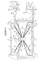
- network the different communication stations grouped within the same entity called "network" are in fact located in different geographic locations of the same country or the same region. from this country. Also, it is advantageous and advantageous, according to a characteristic of the invention, to materialize this network in each station of the network or at least in the main stations of this network by means of a synoptic table reproducing schematically the geographical limits of the network and indicating the location of the various stations of this network.
- Such a materialization of a network is envisaged in the improved communication unit described in FIGS. 4 and 5, such a unit being able to come in addition to the communication unit described in FIGS. 2 and 3.
- This synoptic table 30 shown in FIG. 4 is arranged in the premises of a station. On this synoptic diagram is shown the geographical limits of a network comprising several stations, such as a hexagon 31 simulating for example geographical limits of France, with indication of three stations ST1, ST2, ST3 symbolizing three cities constituting a network.
- Each station is materialized on the synoptic table 30 by means of a display means constituted for example by two light-emitting diodes 32, 33, located close to each other, a diode diffusing a red color and the another diode diffusing a green color for example, With each pair of diodes 32, 33 materializing a station, there is associated a pair of control means 34, 35 such as push buttons for controlling the lighting of these two diodes, respectively. The role of these diodes will be explained later.
- This synoptic table 30 therefore forms part of a communication unit U 'installed in at least one room of a network station.
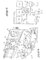
- This communication unit U ' is completed by at least one integrated assembly 36 resting on a support 37 such as a table situated substantially opposite the synoptic table 30.
- This assembly 36 comprises a display unit 7 with two lines 7a, 7b , a switch 11, a badge reader unit 15 16, these elements corresponding and having the same function as those of the communication unit U shown in FIGS. 2 and 3.
- This assembly 36 also includes a transmission unit formed by a microphone 9 supported by a stand 39 and playing the same role as the transmission capsule 9 of the communication unit U of FIG. 2.
- the reception unit is constituted by a central loudspeaker 10 situated in an appropriate place in the room containing the communication unit U ', and playing the same role as the reception capsule 10 of the communication unit U of fig. 2.
- the communication unit U ′ is advantageously supplemented by a projection device 41 which makes it possible to view on a screen 42 the photograph of the person speaking at a given instant, and of an alpha-digital display board 43 having several lines 11 to ln and several columns, for example four in number c1 to cn, to give information on the state of the conference, as will be described later.
- control means 44, 45, 46 each consisting of a button- pushbutton located for example at the bottom of the synoptic table 30. The functions of these pushbuttons will be explained below.
- the switching unit U In connection with the alpha-digital display table 43, the switching unit U 'comprises a microprocessor P1 associated with a control unit C1, this processor P1 being connected to the display table 43 and to the synoptic table 30 by l 'L'6 bidirectional link.
- each of the stations ST1, ST2, ... STn is equipped with a communications unit U as shown in FIG. 2, and that a person P1 from station ST1 is trying to reach a person P2 from station ST2.
- This person is part of the directory of the memory M1 which contains all the known correspondents and likely to be called.
- Each correspondent is identified, for example, by physical or moral name, a prefix and their telephone number.
- this call signal can simply result in a conventional ringing.
- a person from the station ST2 warned by this ringing will then respond to this call signal by simply picking up the handset 8 of the communication unit U2 of the station ST2 to enter into communication with the person P1.
- the information coded with their name is automatically displayed on the display line 7a of the communication unit U1 of the station ST1, as soon as this person speaks.
- the telephone conversation can be established normally between them, with simultaneous display of the name of the person speaking or speaker on the display lines 7a of the communication units U1 and U2.
- the present invention it is possible to automatically call back a correspondent. More precisely, once the search for a correspondent has been carried out by sending on line 14 of his telephone number, it is possible to automatically recognize the tone identifying a non-response signal from the correspondent and the tone identifying a signal from line occupation. In the first case, the correspondent can only be called again by launching a complete call sequence as defined above. In the second case, the personalized information of the correspondent identified in the memory M1 is transferred to a second memory M2 in dashed lines in FIG. 3.
- the second main program for automatically calling a correspondent stored in the PROM memory is modified accordingly, the first main program being attached to the constitution of the directory.
- the M2 memory has a low capacity, and in practice, it is possible to store four personalized information therein in order to not complicate the system.
- the device 1 associated with the telephone set 2 when it is in an available state, can automatically re-transmit on the line telephone 14 the telephone number contained in this personalized information. Simultaneously, to notify the user of the telephone set 2, the personalized information is displayed on the display unit 9.
- the corresponding personalized information can be distinguished from the others on the display unit 7 by an overprint for example.
- the program which manages the automatic re-transmission of a telephone number successively takes into account these different information so as to respect a time delay imposed between two successive transmissions of the same phone number.
- the user of the communication unit U1 can at any time interrupt the automatic sequence of calling a correspondent, and use his telephone unit in a conventional manner.
- the personalized information contained in the memory M2 can be erased from this memory at any time.
- the user of the device 1 can compose personalized information of a new correspondent, without necessarily entering this information in the directory of the memory M1.
- the new personalized information is recorded in a third memory (which can itself be constituted by the memory M2).
- the person P1 of the station ST1 can launch a call signal without having automatically personalized the microphone of his communication unit, this microphone being constituted by the transmission capsule 9 of the telephone handset 8, handset which will not be lifted only when someone from station ST2 has answered.
- this microphone being constituted by the transmission capsule 9 of the telephone handset 8, handset which will not be lifted only when someone from station ST2 has answered.
- communication comes down to pure and simple classic communication between two classic telephone sets.
- Each called communication unit answers the call signal as in the present case.
- the display line 7a of each communication unit of the conference displays, at all times, the name of the speaker.
- these two stations are the stations ST1 and ST3, each of these stations being equipped with a communication unit conforming to that shown in FIG. 2, and that a person P1 from station ST1 is trying to reach a person P3 from station ST3.
- the person P1 personalizes his microphone (transmission capsule 9 of the handset 8) of his communication unit U1, by inserting his badge 16 in sector 15, and the establishment of communication with the person P3 takes place as in the previous cases.
- this data before being transmitted, can be previously recorded in the recorder 20 of the transmission unit.
- These data or messages can be transmitted by a station to another station without these two stations being in verbal communication.
- the message is automatically recorded on the recording unit 20 of the receiving station.
- the recording medium consists of a cassette for example, which can consequently record several messages, it is advantageous, in accordance with the invention, to simultaneously print on the printing unit 21 the name of the recipient of this message with a digital indication giving the position of the start of the message on the cassette.
- the person wishing to read a message can only do so after having introduced his badge 16 in the reader 15 to be sure that this message will be restored on the printer unit 21 or on the line d display 7a to the person to whom this message is actually intended.
- the beginning of the message is always preceded by the name of the recipient, a name which is then compared with the name recorded on the badge 16 of the person who wants to read the message.
- each station ST1, ST3 comprises several communication units U like that illustrated in FIG. 2.
- This configuration differs from the previous one, because it must now be taken into account that only one speaker can speak at a time.
- the validation of a single microphone is carried out as previously indicated.
- This operation is carried out simply by operating the switch 11 of the communication unit U, the person having previously introduced his badge 16, bearing his name in the reader of his unit.
- the name of the person who wishes to speak is transmitted to the other conference units by one of the aforementioned additional channels of the specialized link 50, without disturbing a communication in progress.
- the initiator of the conference may then give the floor to that requester as soon as he or she deems it useful.
- this applicant can speak automatically through his microphone (transmission capsule 9 of the telephone handset 8 of the communication unit U), but this type of intervention can be detrimental to the smooth running of the conference if this procedure is used for the purpose of obstruction.
- any person participating or not in the conference set up can transmit data at any time via the second channel of the dedicated link 50 to one or more people if this data transmission channel is free.
- each communication unit U (fig. 2) is provided with three indicators V1, V2, V3.
- a communications network comprising five stations ST1, ST2, ST3, ST4, ST5 installed in a star configuration with a central station ST3 connected to each of the other stations by a dedicated link 50 and a central switch 51, so to allow any of these stations to call one or more of the other stations.
- these stations can simultaneously be linked together in pairs by a telephone line 2 of the switched network, as also shown in FIG. 1.
- stations ST3, ST4 and ST5 are equipped with a communication unit U 'as described in figs 4 and 5.
- This particular network is shown diagrammatically on each synoptic table 30 of the stations ST3, ST4, ST5.
- a) either press the push button 44 of the synoptic table 30 which has the function of allowing a general call to be made to all the stations of the network, in particular to stations ST4 and ST5 in the example envisaged.
- the initiator of the conference presses the push button 45 ensuring an execution function, that is to say that the communication unit U 'of the station ST3 transmits a call signal to stations ST4 and ST5 on the network.
- This call signal is then displayed on the synoptic table of stations ST4, ST5. More precisely, on each synoptic table 30, the diode 32 of each station called is flashing on with red color, while the diode 32 of the station from which the call signal emanates is lit so fixed by also diffusing a red light.
- the station transmitting a call signal is necessarily identified by the fact that one of the stations materialized on the synoptic table 30 has its diode 32 lit by fixed way by diffusing a red light.
- the person present in front of the synoptic 30 can also know if his station is called by the simple fact that the diode 32 materializing this station on the synoptic table 30 is lit in a flashing way by also diffusing a light of red color.
- any person located near the synoptic table 30 of a called station can know, thanks to this table, the origin of a call signal and the invitation which is made to this station to participate in a conference. for example.
- each station called transmits a response signal to the station from which the call originates. For this, it suffices for a person at a station called to press the control button 34 associated with the diode 32 materializing his station on the synoptic table 30, in order to make the lighting of this diode fixed. Once this operation has been carried out, all the diodes 32 of the synoptic tables 30 of all the stations which are to participate in the conference are permanently on.
- the conference itself can begin.
- the diode 33 of the synoptic table which indicates the station from which the call signal emanates, is fixedly lit and diffuses a green light. This information is also reproduced on all the synoptic tables 30 of the stations invited to the conference. This means that the conference initiator is ready to speak. As in the previous cases, only one person can speak at a time, the other microphones 9 of the other stations being automatically switched off.
- the corresponding diode 33 materializing the station from which the request originated lights up permanently (green color). This command is carried out automatically as soon as the person speaks in front of his microphone 9.
- a single diode 33 can be permanently lit (green color), which makes it possible to identify the speaker's station.
- anyone participating or not in the conference can transmit data or messages to at least one station whether or not participating in a conference in progress.
- the initiator of a conference first calls a station, then secondly the person or people of these stations invited to participate in the conference by conversing with the people of the stations called who answered his call.
- a communication unit U ′ can be equipped with a microprocessor P1 containing a set of calling programs.
- a control unit C 1 the instigator of a conference types, for example, on a keyboard of this control unit, or on the keyboard 4 of the communication unit U of FIG. 2, a program number.
- the corresponding program contains the names of the people who can be directly called, the names of these people and the names of their stations appearing in clear on the different lines of the display table 43 of FIG. 4, with automatic indication of the stations called on each screen 30 of these stations with the conventions previously defined for the lighting of the diodes 32 and 33 materializing the stations.
- Table 43 includes several lines 11 to ln, and four columns c1 to cn.
- a line in table 43 is allocated to a station, the first column indicating by the illumination of a character (X for example) the answer of the called person (the screen 30 showing only the station), the second column displaying the name of the station where the person called is located, the third column displaying the name of the person called, and the fourth column displaying the priority number, during the conference, requests for intervention from the persons called, this number being decremented by one when the request for intervention from another person is satisfied or that a requester for a request for intervention has carried out the cancellation of its request, for example by returning the switch 11 of its communication unit U 'to its initial position.
- the speaker's photo is displayed on the screen 42 via a projector 41 which has a file (fig. 5) in which are stored micro-films or microfiches reproducing the photo of the potential people likely to participate. at a conference.
- the projector 41 is controlled by a code recorded on the badge 16 of each person, a code which is transmitted to the control unit of the projector 41 as soon as the person speaks.
- a conference it is possible to enter into a conference or to cause a conference to be called by a person foreign to a network, that is to say by a person not located in a station of a network.
- a person not present in one of these stations can be connected to one of them by a telephone line 2 of the network switched.
- This person has for this purpose special equipment contained for example in a briefcase 60.
- This briefcase comprises at least one conventional telephone handset 61 connected to a transmission unit 62 comprising in particular a badge reader, an interface circuit 63 to which is connected the conventional telephone handset 65 of a conventional telephone set 66 which can for example be connected to the station ST2 by a telephone line 2 of the switched network.
- the badge 16 of this person must also include a validation code compatible with the network to authorize access.
- a station ST6 forming part of another communication network to communicate with the network constituted by the stations ST1, ST2, ST3, ST4, ST5, by connecting to one of these stations, for example the STS station, via a telephone line 2 of the switched network, with of course recognition of an access code to this network.
- Any station on a network can therefore be equipped with either a communication unit U such as that shown in FIG. 2, or a communication unit U 'such as that shown in FIG. 4, or own these two units.
- Each station can also include several of these units which are linked together locally, and the method according to the invention can also be applied between several communication units of the same station.
- the equipment of a station U could be supplemented by a clock device represented schematically by H in FIG. 3.
- This device would make it possible to automatically call a correspondent at a predetermined time.
- the information concerning this correspondent has been transferred beforehand from the memory M1 to the memory M2 of lower capacity.
- the processor organizes the call of the correspondent, automatically, as was explained during the description of the function of the memory M2 to following a busy signal from a correspondent's station In this way, a previously recorded message could be transmitted at any time desired.
- the microphones of people likely to participate in a conference and their control systems could advantageously be arranged in such a way that only the microphone of the speaker who wishes to speak is validated or opened and this only after he said a predetermined keyword, while all the other microphones remain closed.
- the keyword could be a word that is not part of everyday language and that can be easily detected by the system. At the end of his speech, the speaker again pronounces this key word, which will cause his microphone to be closed.
Landscapes
- Engineering & Computer Science (AREA)
- Multimedia (AREA)
- Signal Processing (AREA)
- Computer Vision & Pattern Recognition (AREA)
- Telephonic Communication Services (AREA)
Applications Claiming Priority (2)
| Application Number | Priority Date | Filing Date | Title |
|---|---|---|---|
| FR8013003 | 1980-06-11 | ||
| FR8013003A FR2484747A1 (fr) | 1980-06-11 | 1980-06-11 | Procede et dispositif pour etablir des communications bidirectionnelles et/ou multidirectionnelles entre differentes personnes regroupees en differentes stations geographiquement eloignees et reliees entre elles par des lignes telephoniques |
Publications (2)
| Publication Number | Publication Date |
|---|---|
| EP0041902A1 EP0041902A1 (fr) | 1981-12-16 |
| EP0041902B1 true EP0041902B1 (fr) | 1986-04-02 |
Family
ID=9242971
Family Applications (1)
| Application Number | Title | Priority Date | Filing Date |
|---|---|---|---|
| EP81400921A Expired EP0041902B1 (fr) | 1980-06-11 | 1981-06-10 | Procédé et dispositif pour établir des communications bidirectionnelles et/ou multidirectionnelles entre différentes personnes regroupées en différentes stations géographiquement éloignées et reliées entre elles par des lignes téléphoniques |
Country Status (5)
| Country | Link |
|---|---|
| US (1) | US4805205A (enExample) |
| EP (1) | EP0041902B1 (enExample) |
| JP (1) | JPS5726957A (enExample) |
| DE (1) | DE3174233D1 (enExample) |
| FR (1) | FR2484747A1 (enExample) |
Cited By (4)
| Publication number | Priority date | Publication date | Assignee | Title |
|---|---|---|---|---|
| US6212547B1 (en) | 1993-10-01 | 2001-04-03 | Collaboration Properties, Inc. | UTP based video and data conferencing |
| US6594688B2 (en) | 1993-10-01 | 2003-07-15 | Collaboration Properties, Inc. | Dedicated echo canceler for a workstation |
| US6898620B1 (en) | 1996-06-07 | 2005-05-24 | Collaboration Properties, Inc. | Multiplexing video and control signals onto UTP |
| US7185054B1 (en) | 1993-10-01 | 2007-02-27 | Collaboration Properties, Inc. | Participant display and selection in video conference calls |
Families Citing this family (36)
| Publication number | Priority date | Publication date | Assignee | Title |
|---|---|---|---|---|
| FR2484747A1 (fr) * | 1980-06-11 | 1981-12-18 | Faye Andre | Procede et dispositif pour etablir des communications bidirectionnelles et/ou multidirectionnelles entre differentes personnes regroupees en differentes stations geographiquement eloignees et reliees entre elles par des lignes telephoniques |
| US4645872A (en) * | 1982-04-01 | 1987-02-24 | John Hopkins University | Videophone network system |
| GB2151870B (en) * | 1983-12-22 | 1986-12-31 | Anugraha Hotels Limited | Conference communications system |
| GB2151825B (en) * | 1983-12-22 | 1986-10-08 | Anugraha Hotels Limited | Conference communications systems |
| DE3542886A1 (de) * | 1985-12-04 | 1987-06-11 | Helmut Braehler | Elektroakustische diskussionsanlage |
| US4653090A (en) * | 1985-12-16 | 1987-03-24 | American Telephone & Telegraph (At&T) | Graphics based call management |
| JPS62200857A (ja) * | 1986-02-28 | 1987-09-04 | Mitsubishi Electric Corp | デジタル電話機の表示方式 |
| US4747121A (en) * | 1986-05-01 | 1988-05-24 | Educational Technology, Inc. | Remote control slide projector module |
| JPH0226140A (ja) * | 1988-07-15 | 1990-01-29 | Nec Corp | コードレス電話方式 |
| US5003532A (en) * | 1989-06-02 | 1991-03-26 | Fujitsu Limited | Multi-point conference system |
| EP0410378A3 (en) * | 1989-07-26 | 1992-08-05 | Hitachi, Ltd. | Multimedia telemeeting terminal device, communication system and manipulation method thereof |
| US5073927A (en) * | 1989-08-29 | 1991-12-17 | Motorola, Inc. | Imaging identification method for a communication system |
| WO1992021211A1 (en) | 1991-05-21 | 1992-11-26 | Videotelecom Corp. | A multiple medium message recording system |
| US5805677A (en) * | 1991-07-11 | 1998-09-08 | Sbc Technology Resources, Inc. | Apparatus for facilitating the display of information relating to the origin of a third source caller |
| US6141000A (en) * | 1991-10-21 | 2000-10-31 | Smart Technologies Inc. | Projection display system with touch sensing on screen, computer assisted alignment correction and network conferencing |
| JPH07123389A (ja) * | 1993-08-30 | 1995-05-12 | Canon Inc | 通信会議端末装置及び通信会議装置 |
| GB2319137B (en) * | 1993-10-01 | 1998-06-24 | Vicor Inc | Teleconferencing system |
| US5802281A (en) | 1994-09-07 | 1998-09-01 | Rsi Systems, Inc. | Peripheral audio/video communication system that interfaces with a host computer and determines format of coded audio/video signals |
| US5859663A (en) * | 1994-09-15 | 1999-01-12 | Intel Corporation | Audio control system for video teleconferencing |
| US5818514A (en) * | 1994-12-01 | 1998-10-06 | Lucent Technologies Inc. | Video conferencing system and method for providing enhanced interactive communication |
| US5483588A (en) * | 1994-12-23 | 1996-01-09 | Latitute Communications | Voice processing interface for a teleconference system |
| US5844979A (en) | 1995-02-16 | 1998-12-01 | Global Technologies, Inc. | Intelligent switching system for voice and data |
| AU5567896A (en) * | 1995-05-16 | 1996-11-29 | Minnesota Mining And Manufacturing Company | Data conferencing between remotely located participants |
| WO1996038983A1 (en) * | 1995-06-02 | 1996-12-05 | Intel Corporation | Method and apparatus for controlling participant input in a conferencing environment |
| US5559875A (en) * | 1995-07-31 | 1996-09-24 | Latitude Communications | Method and apparatus for recording and retrieval of audio conferences |
| AU6882996A (en) * | 1995-09-04 | 1997-04-09 | British Telecommunications Public Limited Company | Transaction support apparatus |
| FR2761562B1 (fr) * | 1997-03-27 | 2004-08-27 | France Telecom | Systeme de visioconference |
| US6816481B1 (en) * | 1999-04-09 | 2004-11-09 | Sbc Technology Resources, Inc. | Internet caller identification system and method |
| US7809121B2 (en) * | 2001-06-22 | 2010-10-05 | At&T Intellectual Property I, L.P. | Identification of calling devices dialing a universal number to access a telecommunications relay service center |
| US6718021B2 (en) * | 2002-02-19 | 2004-04-06 | Sbc Properties, L.P. | Method and system for presenting customized call alerts in a service for internet caller identification |
| US20040125929A1 (en) * | 2002-12-31 | 2004-07-01 | Pope Stephen M. | Projection caller ID |
| US20050131744A1 (en) * | 2003-12-10 | 2005-06-16 | International Business Machines Corporation | Apparatus, system and method of automatically identifying participants at a videoconference who exhibit a particular expression |
| US6954522B2 (en) * | 2003-12-15 | 2005-10-11 | International Business Machines Corporation | Caller identifying information encoded within embedded digital information |
| US20050249344A1 (en) * | 2004-05-07 | 2005-11-10 | Sbc Knowledge Ventures, L.P. | Network delivery of personalized caller identification |
| US8457614B2 (en) * | 2005-04-07 | 2013-06-04 | Clearone Communications, Inc. | Wireless multi-unit conference phone |
| JP6747025B2 (ja) * | 2016-04-13 | 2020-08-26 | セイコーエプソン株式会社 | 表示システム、表示装置、及び、表示システムの制御方法 |
Family Cites Families (16)
| Publication number | Priority date | Publication date | Assignee | Title |
|---|---|---|---|---|
| US3700814A (en) * | 1969-04-16 | 1972-10-24 | Electronic Data Syst Corp | Portable input-output terminal |
| US3686440A (en) * | 1971-03-26 | 1972-08-22 | Sola Basic Ind Inc | Telephone calling-station identification |
| US3725947A (en) * | 1971-09-30 | 1973-04-03 | Computer Management Syst Inc | Automatic timekeeping and accounting unit |
| JPS532003B2 (enExample) * | 1972-03-27 | 1978-01-24 | ||
| DE2318185A1 (de) * | 1973-04-11 | 1974-10-31 | Telefonbau & Normalzeit Gmbh | Anzeigevorrichtung fuer fernsprechapparate |
| US3932709A (en) * | 1973-04-16 | 1976-01-13 | General Teletronics Incorporated | Electronic business telephone |
| US3870830A (en) * | 1974-01-14 | 1975-03-11 | Tapiei Fa Kuei Liu | Automatic telephone dialer |
| JPS5122762A (en) * | 1974-08-19 | 1976-02-23 | Shogo Nagao | Atsukuseikeiyokino futazaihiitoshiiruno tameno setsuchakuzaiotofusuruhoho |
| US4071710A (en) * | 1975-11-05 | 1978-01-31 | Roy Burnett | Communication-recorder system |
| JPS53135206A (en) * | 1977-04-30 | 1978-11-25 | Nippon Telegr & Teleph Corp <Ntt> | Telephone repeating system |
| FR2390864A1 (fr) * | 1977-05-09 | 1978-12-08 | France Etat | Systeme d'audioconference par liaison telephonique |
| JPS5437511A (en) * | 1977-08-30 | 1979-03-20 | Nec Corp | Conference connection system against incomimg call of junction line |
| JPS5459010A (en) * | 1977-10-19 | 1979-05-12 | Nec Corp | Automatic recalling system for non-answer of called subscriber |
| US4304968A (en) * | 1979-09-24 | 1981-12-08 | Klausner Industries | Telephone electronic answering device |
| US4326123A (en) * | 1980-02-22 | 1982-04-20 | Charles Graham | Telephone credit card system |
| FR2484747A1 (fr) * | 1980-06-11 | 1981-12-18 | Faye Andre | Procede et dispositif pour etablir des communications bidirectionnelles et/ou multidirectionnelles entre differentes personnes regroupees en differentes stations geographiquement eloignees et reliees entre elles par des lignes telephoniques |
-
1980
- 1980-06-11 FR FR8013003A patent/FR2484747A1/fr active Granted
-
1981
- 1981-06-10 EP EP81400921A patent/EP0041902B1/fr not_active Expired
- 1981-06-10 DE DE8181400921T patent/DE3174233D1/de not_active Expired
- 1981-06-11 JP JP9018881A patent/JPS5726957A/ja active Pending
-
1987
- 1987-05-04 US US07/046,588 patent/US4805205A/en not_active Expired - Fee Related
Cited By (26)
| Publication number | Priority date | Publication date | Assignee | Title |
|---|---|---|---|---|
| US7206809B2 (en) | 1993-10-01 | 2007-04-17 | Collaboration Properties, Inc. | Method for real-time communication between plural users |
| US7441001B2 (en) | 1993-10-01 | 2008-10-21 | Avistar Communications Corporation | Real-time wide-area communications between ports |
| US6351762B1 (en) | 1993-10-01 | 2002-02-26 | Collaboration Properties, Inc. | Method and system for log-in-based video and multimedia calls |
| US6426769B1 (en) | 1993-10-01 | 2002-07-30 | Collaboration Properties, Inc. | High-quality switched analog video communications over unshielded twisted pair |
| US6437818B1 (en) | 1993-10-01 | 2002-08-20 | Collaboration Properties, Inc. | Video conferencing on existing UTP infrastructure |
| US6594688B2 (en) | 1993-10-01 | 2003-07-15 | Collaboration Properties, Inc. | Dedicated echo canceler for a workstation |
| US6789105B2 (en) | 1993-10-01 | 2004-09-07 | Collaboration Properties, Inc. | Multiple-editor authoring of multimedia documents including real-time video and time-insensitive media |
| US7908320B2 (en) | 1993-10-01 | 2011-03-15 | Pragmatus Av Llc | Tracking user locations over multiple networks to enable real time communications |
| US6959322B2 (en) | 1993-10-01 | 2005-10-25 | Collaboration Properties, Inc. | UTP based video conferencing |
| US7054904B2 (en) | 1993-10-01 | 2006-05-30 | Collaboration Properties, Inc. | Marking and searching capabilities in multimedia documents within multimedia collaboration networks |
| US7152093B2 (en) | 1993-10-01 | 2006-12-19 | Collaboration Properties, Inc. | System for real-time communication between plural users |
| US7185054B1 (en) | 1993-10-01 | 2007-02-27 | Collaboration Properties, Inc. | Participant display and selection in video conference calls |
| US6237025B1 (en) | 1993-10-01 | 2001-05-22 | Collaboration Properties, Inc. | Multimedia collaboration system |
| US7730132B2 (en) | 1993-10-01 | 2010-06-01 | Ludwig Lester F | Storing and accessing media files |
| US7437411B2 (en) | 1993-10-01 | 2008-10-14 | Avistar Communications Corporation | Communication of a selected type over a wide area network |
| US7421470B2 (en) | 1993-10-01 | 2008-09-02 | Avistar Communications Corporation | Method for real-time communication between plural users |
| US7433921B2 (en) | 1993-10-01 | 2008-10-07 | Avistar Communications Corporation | System for real-time communication between plural users |
| US7437412B2 (en) | 1993-10-01 | 2008-10-14 | Avistar Communications Corporation | Real-time communication of a selected type |
| US7412482B2 (en) | 1993-10-01 | 2008-08-12 | Avistar Communications Corporation | System for managing real-time communications |
| US6212547B1 (en) | 1993-10-01 | 2001-04-03 | Collaboration Properties, Inc. | UTP based video and data conferencing |
| US7444373B2 (en) | 1993-10-01 | 2008-10-28 | Avistar Communications Corporation | Wireless real-time communication |
| US7487210B2 (en) | 1993-10-01 | 2009-02-03 | Avistar Communications Corporation | Method for managing real-time communications |
| US7398296B2 (en) | 1993-10-01 | 2008-07-08 | Avistar Communications Corporation | Networked audio communication over two networks |
| US7822813B2 (en) | 1993-10-01 | 2010-10-26 | Ludwig Lester F | Storing and accessing media files |
| US7831663B2 (en) | 1993-10-01 | 2010-11-09 | Pragmatus Av Llc | Storage and playback of media files |
| US6898620B1 (en) | 1996-06-07 | 2005-05-24 | Collaboration Properties, Inc. | Multiplexing video and control signals onto UTP |
Also Published As
| Publication number | Publication date |
|---|---|
| DE3174233D1 (en) | 1986-05-07 |
| EP0041902A1 (fr) | 1981-12-16 |
| JPS5726957A (en) | 1982-02-13 |
| US4805205A (en) | 1989-02-14 |
| FR2484747B1 (enExample) | 1983-11-25 |
| FR2484747A1 (fr) | 1981-12-18 |
Similar Documents
| Publication | Publication Date | Title |
|---|---|---|
| EP0041902B1 (fr) | Procédé et dispositif pour établir des communications bidirectionnelles et/ou multidirectionnelles entre différentes personnes regroupées en différentes stations géographiquement éloignées et reliées entre elles par des lignes téléphoniques | |
| US8063928B2 (en) | Videophone system and method | |
| FR2717975A1 (fr) | Procédé et appareil pour relayer une information d'appel vers un dispositif de recherche de personne ou un poste téléphonique de remplacement. | |
| FR2701344A1 (fr) | Machine de télécopie ayant une fonction de réponse. | |
| FR2549662A1 (fr) | Procede et dispositif de transfert de communication de donnees | |
| FR2564271A1 (fr) | Interface de telecommande d'un autocommutateur telephonique | |
| FR2838012A1 (fr) | Dispositif d'interphone pour logement collectif | |
| EP0571518A1 (fr) | Telecopieur a communications diverses | |
| FR2686207A1 (fr) | Telecopieur videotex. | |
| EP1287668B1 (fr) | Procede et dispositif de gestion de mise en relation sans divulgation de numero de telephone | |
| EP1453283A1 (fr) | Système de gestion d'appels téléphoniques entrants | |
| EP1335569A1 (en) | Answer-phone message providing system | |
| FR2860373A1 (fr) | Procede d'acces automatique a une conference telephonique et systeme pour sa mise en oeuvre. | |
| FR2718592A1 (fr) | Dispositif répondeur téléphonique. | |
| FR2687033A1 (fr) | Systeme de communication visiophonique. | |
| KR20200085621A (ko) | 라이브 노인 도움 앱 서비스 | |
| WO2005009016A1 (fr) | Procede et dispositif d'activation d'un transfert d'au moins un message court | |
| FR2838594A1 (fr) | Procede, et equipement, d'etablissement consensuel d'une liaison de communication | |
| WO2002091253A1 (fr) | Procede et systeme de diffusion de messages permettant de garantir la prise de connaissance au moins partielle d'un message par son destinataire | |
| FR2464605A1 (fr) | Appareil de transmission-reception de signaux vocaux et de donnees numeriques | |
| JPH0746338A (ja) | 多重暗証情報供給システム | |
| FR2620292A1 (fr) | Dispositif pour recevoir et aiguiller des appels telephoniques | |
| WO1997039538A1 (fr) | Recepteur d'informations interactif, en particulier poste radiophonique interactif, et procede correspondant de transmission interactive d'informations | |
| FR2697960A1 (fr) | Procédé d'enregistrement à valeur juridique des fac-similés. | |
| FR2867651A1 (fr) | Procede de transmission d'informations par mms et telephones associes |
Legal Events
| Date | Code | Title | Description |
|---|---|---|---|
| PUAI | Public reference made under article 153(3) epc to a published international application that has entered the european phase |
Free format text: ORIGINAL CODE: 0009012 |
|
| AK | Designated contracting states |
Designated state(s): CH DE GB IT NL SE |
|
| 17P | Request for examination filed |
Effective date: 19820526 |
|
| GRAA | (expected) grant |
Free format text: ORIGINAL CODE: 0009210 |
|
| AK | Designated contracting states |
Kind code of ref document: B1 Designated state(s): CH DE GB IT LI NL SE |
|
| PG25 | Lapsed in a contracting state [announced via postgrant information from national office to epo] |
Ref country code: NL Effective date: 19860402 Ref country code: IT Free format text: LAPSE BECAUSE OF FAILURE TO SUBMIT A TRANSLATION OF THE DESCRIPTION OR TO PAY THE FEE WITHIN THE PRESCRIBED TIME-LIMIT;WARNING: LAPSES OF ITALIAN PATENTS WITH EFFECTIVE DATE BEFORE 2007 MAY HAVE OCCURRED AT ANY TIME BEFORE 2007. THE CORRECT EFFECTIVE DATE MAY BE DIFFERENT FROM THE ONE RECORDED. Effective date: 19860402 |
|
| PG25 | Lapsed in a contracting state [announced via postgrant information from national office to epo] |
Ref country code: SE Effective date: 19860430 |
|
| REF | Corresponds to: |
Ref document number: 3174233 Country of ref document: DE Date of ref document: 19860507 |
|
| NLV1 | Nl: lapsed or annulled due to failure to fulfill the requirements of art. 29p and 29m of the patents act | ||
| PLBE | No opposition filed within time limit |
Free format text: ORIGINAL CODE: 0009261 |
|
| STAA | Information on the status of an ep patent application or granted ep patent |
Free format text: STATUS: NO OPPOSITION FILED WITHIN TIME LIMIT |
|
| 26N | No opposition filed | ||
| REG | Reference to a national code |
Ref country code: GB Ref legal event code: 711A |
|
| GBPC | Gb: european patent ceased through non-payment of renewal fee | ||
| GBPC | Gb: european patent ceased through non-payment of renewal fee |
Free format text: 5216, PAGE 577 |
|
| PGFP | Annual fee paid to national office [announced via postgrant information from national office to epo] |
Ref country code: GB Payment date: 19950606 Year of fee payment: 15 |
|
| PGFP | Annual fee paid to national office [announced via postgrant information from national office to epo] |
Ref country code: DE Payment date: 19960514 Year of fee payment: 16 |
|
| PGFP | Annual fee paid to national office [announced via postgrant information from national office to epo] |
Ref country code: CH Payment date: 19960523 Year of fee payment: 16 |
|
| PG25 | Lapsed in a contracting state [announced via postgrant information from national office to epo] |
Ref country code: GB Effective date: 19960610 |
|
| GBPC | Gb: european patent ceased through non-payment of renewal fee |
Effective date: 19960610 |
|
| PG25 | Lapsed in a contracting state [announced via postgrant information from national office to epo] |
Ref country code: LI Free format text: LAPSE BECAUSE OF NON-PAYMENT OF DUE FEES Effective date: 19970630 Ref country code: CH Free format text: LAPSE BECAUSE OF NON-PAYMENT OF DUE FEES Effective date: 19970630 |
|
| REG | Reference to a national code |
Ref country code: CH Ref legal event code: PL |
|
| PG25 | Lapsed in a contracting state [announced via postgrant information from national office to epo] |
Ref country code: DE Free format text: LAPSE BECAUSE OF NON-PAYMENT OF DUE FEES Effective date: 19980303 |