EP0041503B1 - Cabine de vehicule - Google Patents
Cabine de vehicule Download PDFInfo
- Publication number
- EP0041503B1 EP0041503B1 EP80901656A EP80901656A EP0041503B1 EP 0041503 B1 EP0041503 B1 EP 0041503B1 EP 80901656 A EP80901656 A EP 80901656A EP 80901656 A EP80901656 A EP 80901656A EP 0041503 B1 EP0041503 B1 EP 0041503B1
- Authority
- EP
- European Patent Office
- Prior art keywords
- door
- cab
- edge
- platform
- further characterized
- Prior art date
- Legal status (The legal status is an assumption and is not a legal conclusion. Google has not performed a legal analysis and makes no representation as to the accuracy of the status listed.)
- Expired
Links
- 238000010276 construction Methods 0.000 claims abstract description 6
- 230000000712 assembly Effects 0.000 claims 1
- 238000000429 assembly Methods 0.000 claims 1
- 241001124569 Lycaenidae Species 0.000 description 2
- 239000000853 adhesive Substances 0.000 description 2
- 230000001070 adhesive effect Effects 0.000 description 2
- 238000004140 cleaning Methods 0.000 description 1
- 239000004459 forage Substances 0.000 description 1
- 239000011521 glass Substances 0.000 description 1
- 238000003306 harvesting Methods 0.000 description 1
- 238000007493 shaping process Methods 0.000 description 1
- 239000005341 toughened glass Substances 0.000 description 1
Images


Classifications
-
- B—PERFORMING OPERATIONS; TRANSPORTING
- B60—VEHICLES IN GENERAL
- B60J—WINDOWS, WINDSCREENS, NON-FIXED ROOFS, DOORS, OR SIMILAR DEVICES FOR VEHICLES; REMOVABLE EXTERNAL PROTECTIVE COVERINGS SPECIALLY ADAPTED FOR VEHICLES
- B60J5/00—Doors
- B60J5/04—Doors arranged at the vehicle sides
- B60J5/0486—Special type
- B60J5/0487—Special type simplified doors related to cabins of, e.g. golf carts, tractors, jeeps, cranes, forklifts, etc.
-
- B—PERFORMING OPERATIONS; TRANSPORTING
- B62—LAND VEHICLES FOR TRAVELLING OTHERWISE THAN ON RAILS
- B62D—MOTOR VEHICLES; TRAILERS
- B62D33/00—Superstructures for load-carrying vehicles
- B62D33/06—Drivers' cabs
- B62D33/0617—Drivers' cabs for tractors or off-the-road vehicles
Definitions
- This invention relates to a cab for an agricultural, industrial or construction vehicle.
- Self-propelled combine harvesters are subject to an overall width limitation in order to make them acceptable as road-going vehicles. This in turn imposes limitations on engine and cab size and layout.
- engine and cab size and layout In particular, it is well known to arrange the engine and cab alongside one another at the front of the harvester and to provide access to the cab through a door, hinged along its forward upright edge relative to an adjacent sidewall of the cab, on that side of the cab opposite the engine.
- An entry platform is provided alongside the door and thus adds to the overall width of the harvester (see FR-A-2110069 for example). For reasons of safety and convenience the platform cannot be made too narrow.
- the door opens outwards over the platform it has to open sufficiently to allow access by the driver but to be safe it should not open beyond the periphery of the platform.
- the door is hinged along its upright leading edge so as to open forwards over the platform. Steps may be provided up to the rear edge of the platform and a handrail may be provided along the outer edge of the platform and steps and limit outwards opening movement of the door.
- An object of the present invention is to provide a cab for a combine harvester that makes more efficient use of the overall width of the harvester.
- a cab has front, rear and side walls and a driver access door that is hinged along its forward upright edge to an adjacent side wall and opens outwards to the outer limit of an entry platform that is provided alongside the doorway and is mounted from the rear, and is characterized in that the access door is adapted so that it assumes a closed position in which it is angled from said adjacent side wall towards the rear wall so that it faces both sideways and rearwards and at least part of the entry platform lies within the width of the cab between the side walls.
- the angled disposition of the doorway thus improves access to the cab whilst reducing the extent to which the entry platform need extend outwards beyond the line of said adjacent side wall.
- the door is preferably supported by a hinge assembly so that the top of the door moves outwards further than the bottom of the door during opening, thereby giving increased width for access at shoulder height.
- the hinge assembly may be such that the upper hinge member is fixedly connected to the door at one end and is pivotally connected relative to said adjacent side wall at its other end at a point spaced forwards of the leading edge of the door and offset inwards from the plane of the door.
- the upper hinge member may be cranked relative to the door thereby producing an additional outwards movement of the top of the door as it opens.
- the hinge assembly may be such that the hinge axis is inclined rearwards from top to bottom, so that the top and bottom portions of the door move about horizontally displaced centres and thereby produce said outwards movement of the top of the door relative to the bottom of the door.
- a hand-rail may be provided along the outer edge of the platform and steps.
- the hand- rail is pivotally connected to the door at a point spaced away from the hinge axis towards the rear edge of the door, and is shaped so that it moves with the door and allows an increased opening movement.
- the harvester illustrated in Figure 1 comprises a self-propelled chassis 1 carrying a crop elevator 2 at the front for attachment to a harvesting head, grain separating and cleaning apparatus, and grain tanks, all of which may be of conventional construction.
- An engine powers the harvester and is mounted in a housing 3 at the front of the harvester alongside a cab 4 for the driver.
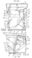
- the cab is detachably mounted on a platform 5 and is shown detached in Figures 2 to 5.
- the cab 4 comprises a floor panel 6 provided with two mounting points 7 at the front by which it is located and bolted onto the platform 5.
- the front wall 8 and the adjacent sections 9 of the side walls are composed of toughened glass panels that are joined by adhesive along their abutting edges 10, and are joined by adhesive to the floor 6 and roof 11.
- the front wall 8 is inclined forwards towards the roof 11 and the rear edges of the side panels 9 are inclined rearwards towards the roof and are connected to upright posts 12, 13.
- the nearside post 12 (as seen in Figure 1) and the adjacent corner post 14 of the cab form a door frame defining a door opening 15 lying in a plane inclined away from the adjacent side panel 9 towards the rear of the cab, the roof being cut away at the adjacent rear corner 16 to match the inclination of the door opening.
- a door 17 is hinged to the cab along its forward edge so as to cooperate with the door opening 15, as described hereinafter.
- An opening window 18 is provided between the offside post 13 (as seen in Figure 3) and the adjacent corner post 19, and a rear window 20 is provided between the two corner posts 14, 18.
- Panels 21, 22 extend along the lower edges of the windows 18, 20 and downwards alongside the rear corner post 14, and are shaped so as to cooperate with corresponding portions of the harvester body.
- the lower portion of the post 13 and the panel 21 cooperate and form a seal with the engine housing 3, the latter being provided with an instrument panel 23.
- the panel 21 cooperates and forms a seal with the housing 24 over the threshing and separating drive mechanism.
- Two mounting points 25 on the panel 21 project rearwards and are used to locate and bolt the cab to the housing 24.
- the door 17 is hinged to the cab top and bottom by a pair of hinges 26, 27, each comprising an arm rigidly connected at one end to the door and pivotally connected at its other end to the cab.
- the lower hinge arm 26 is connected to the door via a bracket 30 and projects forwards along the line of the bottom of the door and is povitally connected to the floor of the cab adjacent the bottom of the post 12 via a bracket 31.
- the upper hinge arm 27 is rigidly connected to the door via a bracket 28 and extends forwards and is cranked at the forward edge of the door to accommodate the change in plane between the door opening 13 and the glass side panel 9.
- the forward end of the arm 27 is pivotally connected to the roof via a bracket 29 at a point spaced forwards of the top of post 12 above the pivotal connection of the lower arm 26 so as to define a substantially vertical hinge axis X-X ( Figure 3).
- the door 17 opens outwards over a triangular shaped entry platform 32 that is formed by a lateral extension of the platform 5.
- the platform 32 extends rearwards from the bottom of the post 12 and widens towards the rear, where a ladder 33 extends down to ground level.
- Figure 5 shows the degree of accessability given to the driver by this arrangement of the door and entry platform.
- the inclination of the door opening 1 5 relative to the side panel 9 of the cab gives limited access before the door opens beyond the cab boundary formed by the plane of panel 9, and thus the door need only open a limited extent beyond this boundary to give adequate accessability.
- the entry platform 32 therefore need only project a limited extent beyond the side boundary of the cab.
- Accessability is also increased by the action of the upper cranked hinge arm 27 which causes the upper part of the door to move away from the side of the cab as it is opened.
- the top of the door therefore leans outwards relative to the bottom of the door when opened, as seen in Figure 5, the access at shoulder height is therefore improved.
- the outwards lean of the top of the door when open can be increased by arranging that the hinge axis X-X is inclined forwards towards the top of the door, for example, by lengthening the forward projecting end of the hinge arm 27 and shifting the bracket 29 forwards in Figure 3.
- the top edge of the door then swings about a hinge centre that is displaced forwards of the corresponding hinge centre of the bottom edge of the door and thus the top edge moves outwards relative to the bottom edge as the door opens beyond the plane of the adjacent side wall 9.
- the door may be hinged about an axis that extends substantially parallel to the edge of the door and which is inclined forwards towards the top of the door so that as the door opens the top of the door moves outwards relative to the bottom of the door solely as a result of said forwards inclination of the hinge axis.
- the post 12 may be inclined forwards at its top in Figure 3 and the same hinge arm 26 used both top and bottom in hinging the door to the cab.
- the axis X-X in the illustrated embodiment is substantially vertical as seen in Figures 4 and 5 but it will be appreciated that this may vary.
- a hand-rail 34 is provided along the outer periphery of the platform and steps and serves to limit outwards opening movement of the door.
- the hand-rail 34 comprises a portion 35 above the periphery of the platform and a parallel rail 36 beneath it. Both rails 35, 36 are pivotally connected to the leading edge of the door 17 via pairs of brakcets 37, 38.
- a releasable latch mechanism 39 connects the hand-rail to the platform 32.
- the hand-rail 34 and its connection to the door have been modified so that the hand- rail 34 moves outwards with opening of the door and thus allows a larger opening movement.
- the hand-rail 34 is also supported at a point 44 on the platform or ladder so as to allow said movement of the hand-rail.
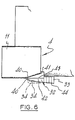
- the entry platform 32, or at least part of the entry platform, and the ladder 33 may be adapted so that they can be folded against the side of the combine harvester.
- the platform 32 may comprise an inner fixed section 41 and an outer section 42 that is hinged to the fixed section 41 so that it can be swung downwards beneath it, the two sections abutting along a line 43 parallel to the side wall of the cab as shown in Figure 6.
- the width of the harvester can thus be reduced by folding the ladder 33 against the side of the combine, folding the platform section 42 down, and swinging the hand-rail 34 inwards.
- a cab such as that illustrated may be used on other machines besides a combine harvester.
- it can be used on other agricultural vehicles such as forage harvesters, or industrial or construction vehicles or machines.
Landscapes
- Engineering & Computer Science (AREA)
- Mechanical Engineering (AREA)
- Chemical & Material Sciences (AREA)
- Combustion & Propulsion (AREA)
- Transportation (AREA)
- Body Structure For Vehicles (AREA)
- Harvester Elements (AREA)
Abstract
Claims (14)
Applications Claiming Priority (2)
| Application Number | Priority Date | Filing Date | Title |
|---|---|---|---|
| GB7930255 | 1979-08-31 | ||
| GB7930255 | 1979-08-31 |
Publications (2)
| Publication Number | Publication Date |
|---|---|
| EP0041503A1 EP0041503A1 (fr) | 1981-12-16 |
| EP0041503B1 true EP0041503B1 (fr) | 1983-10-12 |
Family
ID=10507529
Family Applications (1)
| Application Number | Title | Priority Date | Filing Date |
|---|---|---|---|
| EP80901656A Expired EP0041503B1 (fr) | 1979-08-31 | 1980-08-09 | Cabine de vehicule |
Country Status (11)
| Country | Link |
|---|---|
| US (1) | US4416486A (fr) |
| EP (1) | EP0041503B1 (fr) |
| JP (1) | JPS56501483A (fr) |
| CA (1) | CA1164502A (fr) |
| DE (1) | DE3065287D1 (fr) |
| DK (1) | DK188381A (fr) |
| FI (1) | FI802727A (fr) |
| GB (1) | GB2057981B (fr) |
| IT (1) | IT1132564B (fr) |
| NZ (1) | NZ194573A (fr) |
| WO (1) | WO1981000541A1 (fr) |
Families Citing this family (27)
| Publication number | Priority date | Publication date | Assignee | Title |
|---|---|---|---|---|
| US4652043A (en) * | 1985-04-15 | 1987-03-24 | New Holland Inc. | Access door for harvester operator's cab |
| US4605259A (en) * | 1985-04-15 | 1986-08-12 | New Holland Inc. | Operator's cab for crop harvesting machine |
| US4957324A (en) * | 1989-07-13 | 1990-09-18 | J.I. Case Company | Combination guide rail door handle |
| US5284349A (en) * | 1992-11-30 | 1994-02-08 | May-Wes Manufacturing, Inc. | Cab step assembly |
| US5658040A (en) * | 1994-12-13 | 1997-08-19 | Caterpillar, Inc. | Enclosure for an operator having an angled rear window |
| US5906411A (en) * | 1997-06-20 | 1999-05-25 | New Holland North America, Inc. | Combine harvester cab layout for visibility, serviceability and space |
| DK0842842T3 (da) | 1996-11-12 | 2003-08-25 | Cnh Belgium Nv | Indretning af et mejetærskerførerhus til udsyn, formålstjenlighed og plads |
| US5791727A (en) * | 1996-11-18 | 1998-08-11 | Case Corporation | Openable combine cab window assembly |
| US6179312B1 (en) | 1997-03-14 | 2001-01-30 | Freightliner Llc | Retractable stairway for entering and exiting a vehicle |
| US6178364B1 (en) | 1999-02-12 | 2001-01-23 | Freightliner Corporation | Method of controlling a retractable stairway assembly |
| US6264222B1 (en) | 1999-02-25 | 2001-07-24 | Freightliner Llc | Retractable stairway assembly for a vehicle |
| US6247746B1 (en) | 1999-12-02 | 2001-06-19 | Caterpillar Inc. | Door assembly for a cab of an agricultural tractor |
| CA2321484C (fr) * | 2000-09-29 | 2008-01-15 | Komatsu Utility Europe S.P.A. | Cabine pour machine de terrassement |
| US6971657B2 (en) * | 2003-03-13 | 2005-12-06 | Kalmar Industries Usa, Llc | Driver access system for motor truck tractor |
| US6935676B2 (en) * | 2003-12-30 | 2005-08-30 | Mitsubishi Jidosha Kogyo Kabushiki Kaisha | Vehicle with door capable of swinging horizontally |
| US6942282B1 (en) | 2004-06-17 | 2005-09-13 | Cnh America Llc | Wrap-around cab control layout for bale wagon |
| US7497501B2 (en) * | 2006-12-20 | 2009-03-03 | Caterpillar Inc. | Ergonomic operator compartment access system and method |
| DE102007011367A1 (de) * | 2007-03-07 | 2008-09-11 | Claas Selbstfahrende Erntemaschinen Gmbh | Landwirtschaftliches Arbeitsfahrzeug mit beweglicher Fahrerkabine |
| US7578247B2 (en) * | 2007-06-29 | 2009-08-25 | Cnh America Llc | Seed tank access assembly for planters |
| US8033482B2 (en) * | 2008-08-14 | 2011-10-11 | Cnh America Llc | Pivoting handrail for an agricultural sprayer |
| JP6178149B2 (ja) * | 2013-07-24 | 2017-08-09 | ヤンマー株式会社 | トラクター |
| US10385538B2 (en) * | 2015-04-28 | 2019-08-20 | Guangxi Liugong Machinery Co., Ltd. | Operator's cab arrangement for a construction machine |
| USD826994S1 (en) * | 2017-06-05 | 2018-08-28 | Cnh Industrial America Llc | Forage harvester |
| US10696232B2 (en) * | 2017-11-16 | 2020-06-30 | Cnh Industrial America Llc | Split deck rail |
| CN109649508A (zh) * | 2019-01-29 | 2019-04-19 | 江苏徐工工程机械研究院有限公司 | 驾驶室框架、驾驶室和工程车辆 |
| JP7338990B2 (ja) * | 2019-03-01 | 2023-09-05 | 株式会社小松製作所 | 運転室および作業車両 |
| US10947696B2 (en) * | 2019-07-01 | 2021-03-16 | Caterpillar Inc. | Ingress/egress arrangement for machine |
Family Cites Families (12)
| Publication number | Priority date | Publication date | Assignee | Title |
|---|---|---|---|---|
| US116287A (en) * | 1871-06-27 | Improvement in burglar-proof safes | ||
| GB925260A (en) * | 1961-01-07 | 1963-05-01 | Bristol Metal Components Ltd | Improvements in cabs or covers for the drivers of tractor vehicles |
| US3278222A (en) * | 1964-06-08 | 1966-10-11 | Excel Ind | Cab enclosure for agricultural implements |
| US3279843A (en) * | 1964-06-18 | 1966-10-18 | Ibex Motor Truck Corp | Truck cab construction |
| NL7015918A (fr) * | 1970-10-30 | 1972-05-03 | ||
| US3802530A (en) * | 1972-04-26 | 1974-04-09 | Deere & Co | Tractor cab |
| GB1330983A (en) * | 1972-08-31 | 1973-09-19 | Simon Eng Dudley Ltd | Vehicle having access between the drivers cab and a load carrying platform |
| US3998489A (en) * | 1974-01-03 | 1976-12-21 | Sperry Rand Corporation | Cab for a harvesting machine |
| DE2424441A1 (de) * | 1974-05-20 | 1975-12-04 | Fahr Ag Maschf | Fahrerkabine fuer maehdrescher und dergleichen |
| US4074788A (en) * | 1976-08-09 | 1978-02-21 | Steiger Tractor Inc. | Tractor door latch |
| DE2733166A1 (de) * | 1977-07-22 | 1979-02-01 | Kloeckner Humboldt Deutz Ag | Fahrzeugtuer, insbesondere fuer eine fahrerkabine |
| US4221274A (en) * | 1979-02-12 | 1980-09-09 | Martin Robert P | Lift truck cab with movable back wall portion |
-
1980
- 1980-08-05 NZ NZ194573A patent/NZ194573A/en unknown
- 1980-08-07 GB GB8025763A patent/GB2057981B/en not_active Expired
- 1980-08-09 JP JP50202280A patent/JPS56501483A/ja active Pending
- 1980-08-09 EP EP80901656A patent/EP0041503B1/fr not_active Expired
- 1980-08-09 WO PCT/EP1980/000076 patent/WO1981000541A1/fr active IP Right Grant
- 1980-08-09 US US06/253,744 patent/US4416486A/en not_active Expired - Fee Related
- 1980-08-09 DE DE8080901656T patent/DE3065287D1/de not_active Expired
- 1980-08-14 IT IT24162/80A patent/IT1132564B/it active
- 1980-08-29 FI FI802727A patent/FI802727A/fi not_active Application Discontinuation
- 1980-08-29 CA CA000359341A patent/CA1164502A/fr not_active Expired
-
1981
- 1981-04-28 DK DK188381A patent/DK188381A/da not_active Application Discontinuation
Also Published As
| Publication number | Publication date |
|---|---|
| CA1164502A (fr) | 1984-03-27 |
| EP0041503A1 (fr) | 1981-12-16 |
| GB2057981B (en) | 1984-05-31 |
| IT1132564B (it) | 1986-07-02 |
| DE3065287D1 (en) | 1983-11-17 |
| JPS56501483A (fr) | 1981-10-15 |
| GB2057981A (en) | 1981-04-08 |
| US4416486A (en) | 1983-11-22 |
| FI802727A (fi) | 1981-03-01 |
| DK188381A (da) | 1981-04-28 |
| WO1981000541A1 (fr) | 1981-03-05 |
| NZ194573A (en) | 1984-07-06 |
| IT8024162A0 (it) | 1980-08-14 |
Similar Documents
| Publication | Publication Date | Title |
|---|---|---|
| EP0041503B1 (fr) | Cabine de vehicule | |
| US5018780A (en) | Vehicle lower body structure | |
| EP1081294B1 (fr) | Excavatrice | |
| US6485084B2 (en) | Rops structure for work vehicle | |
| US4652043A (en) | Access door for harvester operator's cab | |
| US5715667A (en) | Wing deck mounting and lift mechanism | |
| JP5395530B2 (ja) | コンバイン | |
| US3656578A (en) | Vehicle acess ladder | |
| US6012273A (en) | Vertically movable grass catcher for a mower | |
| EP1882605A1 (fr) | Véhicule convertible | |
| US4840423A (en) | Front body structure of a motorcar | |
| US10385538B2 (en) | Operator's cab arrangement for a construction machine | |
| US4131293A (en) | Retractable service ladder | |
| US20030218357A1 (en) | Vehicle body structure | |
| US4291946A (en) | Mirror arrangements to provide side and rear vision for tractor with implements | |
| US4185867A (en) | Harvester with a laterally extending visor structure | |
| CN210226231U (zh) | 作业车 | |
| US2114830A (en) | Vehicle | |
| JPH0713479Y2 (ja) | 刈取収穫機の運転キャビン構造 | |
| EP0692182B1 (fr) | Dispositif d'accès pour moissonneuse agricole | |
| US1715402A (en) | Vehicle body and windshield construction | |
| CN210226230U (zh) | 作业车 | |
| US7175520B2 (en) | Cab arrangement for harvesting combine | |
| RU62356U1 (ru) | Трубчатая рама двери кабины колесной машины | |
| RU2326771C1 (ru) | Рама двери кабины колесного транспортного средства |
Legal Events
| Date | Code | Title | Description |
|---|---|---|---|
| PUAI | Public reference made under article 153(3) epc to a published international application that has entered the european phase |
Free format text: ORIGINAL CODE: 0009012 |
|
| 17P | Request for examination filed |
Effective date: 19810610 |
|
| AK | Designated contracting states |
Designated state(s): DE FR SE |
|
| GRAA | (expected) grant |
Free format text: ORIGINAL CODE: 0009210 |
|
| AK | Designated contracting states |
Designated state(s): DE FR SE |
|
| REF | Corresponds to: |
Ref document number: 3065287 Country of ref document: DE Date of ref document: 19831117 |
|
| ET | Fr: translation filed | ||
| PLBE | No opposition filed within time limit |
Free format text: ORIGINAL CODE: 0009261 |
|
| STAA | Information on the status of an ep patent application or granted ep patent |
Free format text: STATUS: NO OPPOSITION FILED WITHIN TIME LIMIT |
|
| PGFP | Annual fee paid to national office [announced via postgrant information from national office to epo] |
Ref country code: FR Payment date: 19840827 Year of fee payment: 5 |
|
| PGFP | Annual fee paid to national office [announced via postgrant information from national office to epo] |
Ref country code: DE Payment date: 19840917 Year of fee payment: 5 |
|
| PGFP | Annual fee paid to national office [announced via postgrant information from national office to epo] |
Ref country code: SE Payment date: 19840930 Year of fee payment: 5 |
|
| 26N | No opposition filed | ||
| PG25 | Lapsed in a contracting state [announced via postgrant information from national office to epo] |
Ref country code: SE Effective date: 19850810 |
|
| PG25 | Lapsed in a contracting state [announced via postgrant information from national office to epo] |
Ref country code: FR Free format text: LAPSE BECAUSE OF NON-PAYMENT OF DUE FEES Effective date: 19860430 |
|
| PG25 | Lapsed in a contracting state [announced via postgrant information from national office to epo] |
Ref country code: DE Effective date: 19860501 |
|
| REG | Reference to a national code |
Ref country code: FR Ref legal event code: ST |
|
| EUG | Se: european patent has lapsed |
Ref document number: 80901656.1 Effective date: 19860729 |