EP0041490A1 - Pole climbing irons - Google Patents
Pole climbing irons Download PDFInfo
- Publication number
- EP0041490A1 EP0041490A1 EP81850094A EP81850094A EP0041490A1 EP 0041490 A1 EP0041490 A1 EP 0041490A1 EP 81850094 A EP81850094 A EP 81850094A EP 81850094 A EP81850094 A EP 81850094A EP 0041490 A1 EP0041490 A1 EP 0041490A1
- Authority
- EP
- European Patent Office
- Prior art keywords
- pole
- shoe
- support plate
- arm
- climbing
- Prior art date
- Legal status (The legal status is an assumption and is not a legal conclusion. Google has not performed a legal analysis and makes no representation as to the accuracy of the status listed.)
- Withdrawn
Links
Images


Classifications
-
- A—HUMAN NECESSITIES
- A63—SPORTS; GAMES; AMUSEMENTS
- A63B—APPARATUS FOR PHYSICAL TRAINING, GYMNASTICS, SWIMMING, CLIMBING, OR FENCING; BALL GAMES; TRAINING EQUIPMENT
- A63B27/00—Apparatus for climbing poles, trees, or the like
- A63B27/02—Climbing devices for round poles or trees attachable to the feet
Definitions
- the present invention relates to pole climbing irons' intended primarily to be used for climbing tapering poles.
- the climbing iron comprises a shoe-support plate provided with a pole-abutment member, a gripping arm, and a connecting arm interconnecting the pole-abutment member and the gripping arm.
- Pole climbing irons of-this type are in general use in construction and repair works on electric or telegraphic cables. When cables extend across rough country where it is impossible to use vehicles equipped with ladders or elevator platforms, pole climbing irons are the only practically useful tool at the linesman's disposal to reach the top of the pole.
- Modern power-line poles have a standard length of 22 meters and are often made from concrete, since wooden poles of.this length and of acceptable quality are scarce today and consequently expensive. Wooden as well as concrete poles of any considerable length usually taper towards the top. This pole design combines considerable strength with comparatively lom meight.
- the diameter of concrete poles having a length of 22 meters varies from appr. 510 millimeters at the base to appr. 180 millimeters at the top.
- Conventional pole climbing irons cannot be used to climb poles showing such a considerable difference in diameters.
- pole climbing irons which are intended to be used for climbing conical poles.
- the iron extends upwards along the leg of the user to the level of his knee, at which point are positioned a support and a gripping arm which are interconnected by an adjustment mechanism.
- the latter thus being positioned at knee--level, is manually operable by the user to adjust the climbing iron to the changes in diameter vertically along the pole.
- this kind of climbing iron is heavy and clumsy and for this reason is not extensively used. Because the points of support of the climbing iron against the pole are positioned at knee-level where the user's range of movements relative to the pole is limited, this type of climbing iron is uncomfortable and inconvenient to use.
- the pole climbing iron in accordance with the subject invention is intended to allow climbing of conically tapering poles with the same safety and agility as with conventional pole climbing irons used to climb poles having the same diameter throughout.
- the climbing iron in accordance with the subject invention makes it possible to climb poles that are taller than the ones referred to above, e.g. about 45 meters,a pole height required for the 400 kU lines now being planned.
- the climbing irons in accordance with the present invention are characterised in that the shoe-support plate to which is attached the pole-abutment member is connected with the connecting arm via a ratchet mechanism by means of which the shoe-support plate can be displaced relative to the connecting arm for adjustment to the gradually diminishing circumference of tapering poles.
- the climbing iron shown in Fig. 1 comprises a shoe--support plate 1 with a pole-abutment member 2 thereon, a connecting arm 3, and a pole-gripping arm 4.
- the shoe--support plate 1 is provided with the connecting arm 3 via a ratchet mechanism 5.
- the pole abutment member 2 and the pole-gripping arm 4 abut against opposite sides of a cylindrical concrete pole 6 which tapers upwards from a maximum circumference (width) 7 to a minimum circumference (width) 8 at the top 9 of the pole.
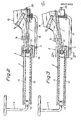
- Fig. 2 shows the climbing iron in a view from the side with a boot 10 secured to the shoe-support plate 1 with the aid of straps 1a.
- the connecting arm 3 consists of two racks 11 and 12, the teeth of which are arranged in vertically facing relationship.
- the racks 11 and 12 are rigidly interconnected at their ends by means of end pieces 13, the forward one, as seen in the toe direction, forming an attachment member on which the gripping arm 4 is mounted.
- the ratchet mechanism 5 is provided with a shaft 14 (see Figs. 4 and 8) on which the shoe-support plate 1 is pivotally mounted.
- a support arm 15 is rigidly connected at one of its ends to the mounting block 16 of the ratchet mechanism 5 while the opposite arm end serves to limit pivotment of the shoe-support plate 1 past a horizontal plane in alignment with the connecting arm 3.
- the supporting end of the support arm 15 is connected to the shoe--support plate 1 by means of a spring means 17 in the form of a helical spring arranged to urge the shoe-support plate away from the support arm over a certain angular distance.
- the pivotal movement of the shoe-support plate relative to the rest of the climbing iron appears from Fig. 3, showing the support plate with the boot thereon in the position at a maximum angle relative to the support arm.
- the pivotal movement of the support plate 1 brings about a corresponding rotation of the shaft 14.
- the shaft extends through the mounting block 16 which is formed with an upper channel 18 in which is mounted the upper rack 11, and with a lower channel 19 in which is mounted the lower rack 12.
- the shaft 14 and its points 1b of attachment to the support plate 1 and mounting in the mounting block 16 appear from Fig. 4.
- the shaft 14 is eccentrically mounted in the casing 16 in a cylindrical rotatable sleeve 20.
- the sleeve bore in which the shaft 14 is mounted is positioned somewhat offset from the sleeve centre.
- One of the points of attachment 1b is positioned at one of the outer ends of the shaft and the other one in a recess 21 formed in the sleeve 20.
- the shaft 14 passes laterally through a double-rim cog wheel 22 which is mounted on the shaft via a hub 23 and is connected to the shaft by means of a free wheel 24 allowing the cog wheel 22 to run freely relative to the shaft in one rotational direction but blocking the cog wheel relative to the shaft in the opposite rotational direction.
- a nut 25 locks the hub of the free wheel 24 relative to the shaft and a cap 26 protects the free-wheel interior from grit and dirt particles.
- the inner gear rim 27 of the cog wheel 22 is in engagement with the upper rack 11 in the position illustrated in Fig. 4.
- a locking arm 28 By pivoting a locking arm 28 over 180°, which arm is connected to the sleeve 20, it is possible to impart to the shaft a parallel movement inside the mounting block 16, whereby the gear rim 27 is moved to its position out of engagement with the upper rack 11 and into engagement with the lower rack 12.
- a spring-loaded pawl 29 on the actuating lever 28 makes it possible to lock the latter in the two pivotal positions.
- the free end of the shaft 14 is provided with an angular arm 30 which is arranged, upon pivotal movement of the shoe-support plate 1 to the upper end position thereof to actuate a pawl 31 engaging an outer gear rim 32 on the cog wheel 22 to bring said pawl out of engagement with the gear rim 32.
- the pawl 31 is pivotally mounted on the mounting block 16 and its function appears from Figs. 5 and 6, which show the ratchet mechanism in a view from theside with the shoe-support plate 1, the racks 11 and 12 and the shaft 14 and the angular arm 30 associated therewith.
- Fig.5 shows the shoe-support plate 1 in support position with the ratchet mechanism in the non-operative (release) position. Through the action of the a draw spring the pawl arm 31 is urged into engagement with the outer gear rim 32 by means of a toothed segment formed on the pawl.
- the free wheel 24 is arranged to run freely when the support plate 1 is pivoted upwards. This pivotal movement therefore will result only in release of the ratchet mechanism.
- the free wheel 24 will block movements of the shaft 14 relative to the cog wheel 22 and rotation of the latter will result in displacement of the mounting block 16 relative to the racks 11 and 12.
- the operating lever 28 assumes its upper blocking position, as illustrated in Fig. 4, pivotal movement downwards of the support plate 1 will bring the pole abutment member 2 closer to the gripping arm 4.
- the gradual narrowing-down of the spacing between the abutment member 2 and the gripping arm 4 may continue until the inner gear rim 27 reaches the forward end piece 13 of the racks, shown in Fig. 7.
- the movements described occur when the linesman is climbing upwards along a pole.
- the climbing iron in accordance with the invention is also provided with a locking means 36 by means of which it is possible to block the shoe-support plate 1 relative to the support arm 15.
- a locking means 36 by means of which it is possible to block the shoe-support plate 1 relative to the support arm 15.
- the locking means may be used in the following manner: after having climbed a slightly conical pole over some distance with the shoe--support plate in blocked position, the user releases the locking means 36, thus adjusting the spacing between the abutment member 2 and the gripping arm 4.
- the climbing iron in accordance with the invention may be used in connection with all types of wooden or concrete poles, irrespecitve of the conicity of the latter.
- the manner of climbing poles with the aid of climbing irons in accordance with the invention is not essentially distinguished from that used with conventional climbing irons.
- it is necessary that the foot is tipped at a steeper angle forwards in order to releave the load on the abutment member and the gripping arm, thus allowing them to slide along the pole surface.
- the teeth of the racks 11 and 12 could face away instead of towards one another.
- the teeth could be directed horizontally instead of vertically.
- the abutment member 2 and the gripping arm 4 could be differently designed and be provided with hard-metal spikes to improve the frictional grip on poles of wood or on ice-covered poles (in the winter).
- the ratchet mechanism 5 may be constructed with e.g. one gear rim which is common to the racks and to the ratchet mechanism.
- the locking device 36 is not essential to the functioning of the inventive object but increases the usefulness of the climbing iron.
Landscapes
- Health & Medical Sciences (AREA)
- General Health & Medical Sciences (AREA)
- Physical Education & Sports Medicine (AREA)
- Holders For Apparel And Elements Relating To Apparel (AREA)
- Ladders (AREA)
Abstract
A pole climbing iron comprising a shoe-support plate (1) provided with a pole-abutment member (2), a gripping arm (4), and a connecting arm (3) interconnecting the pole-abutment member (2) and the gripping arm (4).
The pole climbing iron is intended to be used for climbing tapering poles and is adjustable to the gradually diminishing diameter of tapering poles.
This adjustability is achieved in that the shoe-support plate (1) to which is attached the pole-abutment member (2), is connected to the connecting arm (3) via a ratchet mechanism (5) by means of which the shoe-support plate (1) may be displaced relative to the connecting arm (3).
Description
- The present invention relates to pole climbing irons' intended primarily to be used for climbing tapering poles. The climbing iron comprises a shoe-support plate provided with a pole-abutment member,a gripping arm, and a connecting arm interconnecting the pole-abutment member and the gripping arm.
- Pole climbing irons of-this type are in general use in construction and repair works on electric or telegraphic cables. When cables extend across rough country where it is impossible to use vehicles equipped with ladders or elevator platforms, pole climbing irons are the only practically useful tool at the linesman's disposal to reach the top of the pole.
- Modern power-line poles have a standard length of 22 meters and are often made from concrete, since wooden poles of.this length and of acceptable quality are scarce today and consequently expensive. Wooden as well as concrete poles of any considerable length usually taper towards the top. This pole design combines considerable strength with comparatively lom meight.The diameter of concrete poles having a length of 22 meters varies from appr. 510 millimeters at the base to appr. 180 millimeters at the top. Conventional pole climbing irons cannot be used to climb poles showing such a considerable difference in diameters.
- Certain types of pole climbing irons are known which are intended to be used for climbing conical poles. According to one prior-art construction of pole climbing irons the iron extends upwards along the leg of the user to the level of his knee, at which point are positioned a support and a gripping arm which are interconnected by an adjustment mechanism. The latter, thus being positioned at knee--level, is manually operable by the user to adjust the climbing iron to the changes in diameter vertically along the pole. However, this kind of climbing iron is heavy and clumsy and for this reason is not extensively used. Because the points of support of the climbing iron against the pole are positioned at knee-level where the user's range of movements relative to the pole is limited, this type of climbing iron is uncomfortable and inconvenient to use.
- The most common method of climbing conically tapering poles therefore still is to use an extra pair of climbing irons or pole climbers having a smaller spacing between the support and the gripping arm. The linesman carries with him this extra pair of climbing irons to the level where he finds the first pair to be difficult to use on account of the diminishing diameter of the pole. At this point he puts on the second - extra - pair of irons and uses them to climb to the pole top. The procedure of changing climbing irons is repeated when he climbs down. Obviously, such changing procedures are potential causes of accidents. In addition, linesmen usually have to bring along to the top of the pole tools and other equipment necessary to their work, which makes change of climbing irons difficult.
- The pole climbing iron in accordance with the subject invention is intended to allow climbing of conically tapering poles with the same safety and agility as with conventional pole climbing irons used to climb poles having the same diameter throughout. In addition, the climbing iron in accordance with the subject invention makes it possible to climb poles that are taller than the ones referred to above, e.g. about 45 meters,a pole height required for the 400 kU lines now being planned.
- The climbing irons in accordance with the present invention are characterised in that the shoe-support plate to which is attached the pole-abutment member is connected with the connecting arm via a ratchet mechanism by means of which the shoe-support plate can be displaced relative to the connecting arm for adjustment to the gradually diminishing circumference of tapering poles.
- The invention will be described in closer detail with reference to one embodiment shown in the accompanying drawings, wherein
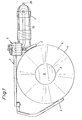
- Fig. 1 is a view from above of a climbing iron in accordance with the invention,
- Figs. 2 and 3 are lateral views of the iron in different operative positions,
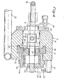
- Fig. 4 is a sectional view along line IV-IV of Fig.3, shown on an enlarged scale,
- Figs. 5 and 6 are lateral viewsof a ratchet mechanism incorporated in the climbing iron and shown in two different operative positions,
- Fig. 7 is a view from above of the iron in a different operative position than the one shown in Fig. 1, and
- Fig. 8 is a sectional view along line IV-IV of Fig.2, showing a second operative position.
- The climbing iron shown in Fig. 1 comprises a shoe--support plate 1 with a pole-
abutment member 2 thereon, a connectingarm 3, and a pole-gripping arm 4. The shoe--support plate 1 is provided with the connectingarm 3 via aratchet mechanism 5. Thepole abutment member 2 and the pole-grippingarm 4 abut against opposite sides of acylindrical concrete pole 6 which tapers upwards from a maximum circumference (width) 7 to a minimum circumference (width) 8 at thetop 9 of the pole. - Fig. 2 shows the climbing iron in a view from the side with a
boot 10 secured to the shoe-support plate 1 with the aid ofstraps 1a. The connectingarm 3 consists of tworacks racks end pieces 13, the forward one, as seen in the toe direction, forming an attachment member on which the grippingarm 4 is mounted. - The
ratchet mechanism 5 is provided with a shaft 14 (see Figs. 4 and 8) on which the shoe-support plate 1 is pivotally mounted. Asupport arm 15 is rigidly connected at one of its ends to themounting block 16 of theratchet mechanism 5 while the opposite arm end serves to limit pivotment of the shoe-support plate 1 past a horizontal plane in alignment with the connectingarm 3. The supporting end of thesupport arm 15 is connected to the shoe--support plate 1 by means of a spring means 17 in the form of a helical spring arranged to urge the shoe-support plate away from the support arm over a certain angular distance. The pivotal movement of the shoe-support plate relative to the rest of the climbing iron appears from Fig. 3, showing the support plate with the boot thereon in the position at a maximum angle relative to the support arm. - The pivotal movement of the support plate 1 brings about a corresponding rotation of the
shaft 14. The shaft extends through themounting block 16 which is formed with anupper channel 18 in which is mounted theupper rack 11, and with alower channel 19 in which is mounted thelower rack 12. Theshaft 14 and itspoints 1b of attachment to the support plate 1 and mounting in themounting block 16 appear from Fig. 4. - The
shaft 14 is eccentrically mounted in thecasing 16 in a cylindricalrotatable sleeve 20. The sleeve bore in which theshaft 14 is mounted is positioned somewhat offset from the sleeve centre. One of the points ofattachment 1b is positioned at one of the outer ends of the shaft and the other one in arecess 21 formed in thesleeve 20. From there, theshaft 14 passes laterally through a double-rim cog wheel 22 which is mounted on the shaft via ahub 23 and is connected to the shaft by means of afree wheel 24 allowing thecog wheel 22 to run freely relative to the shaft in one rotational direction but blocking the cog wheel relative to the shaft in the opposite rotational direction. Anut 25 locks the hub of thefree wheel 24 relative to the shaft and acap 26 protects the free-wheel interior from grit and dirt particles. - The
inner gear rim 27 of thecog wheel 22 is in engagement with theupper rack 11 in the position illustrated in Fig. 4. By pivoting alocking arm 28 over 180°, which arm is connected to thesleeve 20, it is possible to impart to the shaft a parallel movement inside themounting block 16, whereby thegear rim 27 is moved to its position out of engagement with theupper rack 11 and into engagement with thelower rack 12. A spring-loadedpawl 29 on the actuatinglever 28 makes it possible to lock the latter in the two pivotal positions. - The free end of the
shaft 14 is provided with anangular arm 30 which is arranged, upon pivotal movement of the shoe-support plate 1 to the upper end position thereof to actuate apawl 31 engaging anouter gear rim 32 on thecog wheel 22 to bring said pawl out of engagement with thegear rim 32. Thepawl 31 is pivotally mounted on themounting block 16 and its function appears from Figs. 5 and 6, which show the ratchet mechanism in a view from theside with the shoe-support plate 1, theracks shaft 14 and theangular arm 30 associated therewith. Fig.5 shows the shoe-support plate 1 in support position with the ratchet mechanism in the non-operative (release) position. Through the action of the a draw spring thepawl arm 31 is urged into engagement with theouter gear rim 32 by means of a toothed segment formed on the pawl. - When the shoe-support plate 1 is pivoted upwards to its upper end position, the
angular arm 30, which by means I of acontact roller 34 abuts against acam member 35 on thepawl 31, will pivot the latter upwards, disengaging it from theouter gear rim 32. - The
free wheel 24 is arranged to run freely when the support plate 1 is pivoted upwards. This pivotal movement therefore will result only in release of the ratchet mechanism. When the shoe-support plate 1 is pivoted downwards thefree wheel 24 will block movements of theshaft 14 relative to thecog wheel 22 and rotation of the latter will result in displacement of themounting block 16 relative to theracks operating lever 28 assumes its upper blocking position, as illustrated in Fig. 4, pivotal movement downwards of the support plate 1 will bring thepole abutment member 2 closer to the grippingarm 4. The gradual narrowing-down of the spacing between theabutment member 2 and the grippingarm 4 may continue until theinner gear rim 27 reaches theforward end piece 13 of the racks, shown in Fig. 7. The movements described occur when the linesman is climbing upwards along a pole. - When the linesman wants to climb down the pole he pivots the
operating lever 28 to the lower end position, illustrated in Fig. 8. This will bring theinner gear rim 27 to engage thelower rack 12, whereby pivotal movement downwards of the shoe-support plate 1 will result in an increase of the spacing between theabutment member 2 and the grippingarm 4, thus an adjustment of the spacing to the downwardly increasing width (diameter) of the pole. - The climbing iron in accordance with the invention is also provided with a locking means 36 by means of which it is possible to block the shoe-support plate 1 relative to the
support arm 15. This makes it possible to use the climbing irons according to the invention in the same manner as conventional irons, viz. to climb poles with identical diameter throughout. In addition, the locking means may be used in the following manner: after having climbed a slightly conical pole over some distance with the shoe--support plate in blocked position, the user releases the locking means 36, thus adjusting the spacing between theabutment member 2 and thegripping arm 4. - It should be obvious from the aforegoing, therefore, that the climbing iron in accordance with the invention may be used in connection with all types of wooden or concrete poles, irrespecitve of the conicity of the latter. The manner of climbing poles with the aid of climbing irons in accordance with the invention is not essentially distinguished from that used with conventional climbing irons. However, it is necessary that the foot is tipped at a steeper angle forwards in order to releave the load on the abutment member and the gripping arm, thus allowing them to slide along the pole surface. However, this is no disadvantage compared with the use of conventional non-adjustable climbing irons in climbing poles,the diameter of which varies vertically such that the diameter coincides with the spacing between the abutment member and the gripping arm over a very short distance only.
- The invention is not limited to the embodiment described above but several modifications are possible within the scope of the appended claims. For instance, the teeth of the
racks abutment member 2 and thegripping arm 4 could be differently designed and be provided with hard-metal spikes to improve the frictional grip on poles of wood or on ice-covered poles (in the winter). Theratchet mechanism 5 may be constructed with e.g. one gear rim which is common to the racks and to the ratchet mechanism. - The locking
device 36 is not essential to the functioning of the inventive object but increases the usefulness of the climbing iron.
Claims (6)
1. A pole climbing iron for use primarily for climbing tapering poles, comprising a shoe-support plate provided with a pole-abutment member, a pole-gripping arm, and a connecting arm interconnecting the pole-abutment member and the pole-gripping arm, characterised in that the shoe-support plate to which is attached the pole-abutment member, is connected with the connecting arm via a ratchet member by means of which the shoe-support plate is displaceable relative to the connecting arm for adjustment to the gradually diminishing circumference of tapering poles.
2. A pole climbing iron as claimed in claim 1,
characterised in that the connecting arm is in the form of double racks, the ratchet mechanism being arranged to engage in one of said racks for adjus- ment to reducing pole diameters and to engage in the opposite rack for adjustment to increasing pole diameters.
characterised in that the connecting arm is in the form of double racks, the ratchet mechanism being arranged to engage in one of said racks for adjus- ment to reducing pole diameters and to engage in the opposite rack for adjustment to increasing pole diameters.
3. A pole climbing iron as claimed in claim 2,
characterised in that the ratchet mechanism comprises a pawl and a toothed wheel, the latter being connected to a shaft via a free wheel, said shaft arranged when turned in one direction over a predetermined angular distance, to release the pawl and, when turned in the opposite direction, to effect engagement of the free wheel, thus bringing the toothed wheel to turn over some distance.
characterised in that the ratchet mechanism comprises a pawl and a toothed wheel, the latter being connected to a shaft via a free wheel, said shaft arranged when turned in one direction over a predetermined angular distance, to release the pawl and, when turned in the opposite direction, to effect engagement of the free wheel, thus bringing the toothed wheel to turn over some distance.
4. A pole climbing iron as claimed in claim 3,
characterised in that the shaft is rigidly connected with the shoe-support plate which via a spring means is connectud with a support arm projecting from the ratchet mechanism, and in that said shoe-support plate together with tho shaft are pivotable through the action of said spring from a support position, in which the shoe-support plate rests against the support arm to an angular position in which the pawl is released.
characterised in that the shaft is rigidly connected with the shoe-support plate which via a spring means is connectud with a support arm projecting from the ratchet mechanism, and in that said shoe-support plate together with tho shaft are pivotable through the action of said spring from a support position, in which the shoe-support plate rests against the support arm to an angular position in which the pawl is released.
5. A pole climbing iron as claimed in claim 3 or 4,
characterised in that the shaft is eccentrically mounted in a mounting block and operable by means of an operating lever from a position, in which the toothed wheel is in contact with one rack of the connecting arm to a second position in which the toothed wheel is in contact with the opposite rack.
characterised in that the shaft is eccentrically mounted in a mounting block and operable by means of an operating lever from a position, in which the toothed wheel is in contact with one rack of the connecting arm to a second position in which the toothed wheel is in contact with the opposite rack.
6. A pole climbing iron as claimed in any one of the preceding claims, characterised in that the support arm is provided with a means locking the shoe--support plate, said locking means arranged to prevent pivotal movement of the shoe-support plate relative to the support arm.
Applications Claiming Priority (2)
| Application Number | Priority Date | Filing Date | Title |
|---|---|---|---|
| SE8003999 | 1980-05-29 | ||
| SE8003999A SE8003999L (en) | 1980-05-29 | 1980-05-29 | CLOTHING SHOES FOR USE BY POSTS |
Publications (1)
| Publication Number | Publication Date |
|---|---|
| EP0041490A1 true EP0041490A1 (en) | 1981-12-09 |
Family
ID=20341073
Family Applications (1)
| Application Number | Title | Priority Date | Filing Date |
|---|---|---|---|
| EP81850094A Withdrawn EP0041490A1 (en) | 1980-05-29 | 1981-05-27 | Pole climbing irons |
Country Status (2)
| Country | Link |
|---|---|
| EP (1) | EP0041490A1 (en) |
| SE (1) | SE8003999L (en) |
Cited By (14)
| Publication number | Priority date | Publication date | Assignee | Title |
|---|---|---|---|---|
| FR2648451A1 (en) * | 1989-06-16 | 1990-12-21 | Komet | Device for allowing a post to be climbed |
| FR2657022A1 (en) * | 1990-01-17 | 1991-07-19 | Peltier Marcel | Apparatus for climbing a post |
| WO2000074791A1 (en) * | 1999-06-03 | 2000-12-14 | Nagode Aleě, S.P. | Adjustable device for climbing wooden, concrete, polyester or metal posts |
| FR2803385A1 (en) * | 2000-01-05 | 2001-07-06 | Daniel Leglise | Post strength test unit for power lines has integral hydraulic jack can be used in the field |
| CN101081105B (en) * | 2007-06-27 | 2010-05-26 | 刘达 | Container scrambling shoes |
| CN102430229A (en) * | 2011-12-30 | 2012-05-02 | 四川理工学院 | Adaptive squeezer for tapered lamp post |
| CN102886125A (en) * | 2012-10-23 | 2013-01-23 | 四川省电力公司攀枝花电业局 | Anti-falling pole climber |
| CN108553839A (en) * | 2018-03-14 | 2018-09-21 | 长沙学院 | Wire pole climbing machine |
| CN109173192A (en) * | 2018-09-21 | 2019-01-11 | 隋国军 | A kind of multi-functional telegraph pole climbing device |
| CN110721446A (en) * | 2019-11-18 | 2020-01-24 | 国网河南省电力公司孟津县供电公司 | Be used for rainy day climbers to step on pole antiskid |
| CN112473096A (en) * | 2020-11-21 | 2021-03-12 | 蔡薇 | Electric power iron tower overhauls climbing device |
| CN113144546A (en) * | 2021-05-19 | 2021-07-23 | 广东电网有限责任公司 | Climbing rod foot clamp |
| CN113577718A (en) * | 2021-09-18 | 2021-11-02 | 国网湖北省电力有限公司十堰供电公司 | Safe pole climbing device for electric power construction |
| DE102021115807A1 (en) | 2021-06-18 | 2022-12-22 | Thyssenkrupp Steel Europe Ag | Process for treating sponge iron |
Families Citing this family (1)
| Publication number | Priority date | Publication date | Assignee | Title |
|---|---|---|---|---|
| CN117207547B (en) * | 2023-10-27 | 2024-02-20 | 河北建筑工程学院 | Feeding device for carbon fiber winding hydrogen storage tank |
Citations (5)
| Publication number | Priority date | Publication date | Assignee | Title |
|---|---|---|---|---|
| DD49210A (en) * | ||||
| DD56468A (en) * | ||||
| DE134267C (en) * | ||||
| FR1049774A (en) * | 1952-01-23 | 1953-12-31 | Improvements to devices allowing pole ascension | |
| CH338130A (en) * | 1956-01-07 | 1959-04-30 | P Von Arx & Co Ag | Crampons for climbing all kinds of masts |
-
1980
- 1980-05-29 SE SE8003999A patent/SE8003999L/en not_active Application Discontinuation
-
1981
- 1981-05-27 EP EP81850094A patent/EP0041490A1/en not_active Withdrawn
Patent Citations (5)
| Publication number | Priority date | Publication date | Assignee | Title |
|---|---|---|---|---|
| DD49210A (en) * | ||||
| DD56468A (en) * | ||||
| DE134267C (en) * | ||||
| FR1049774A (en) * | 1952-01-23 | 1953-12-31 | Improvements to devices allowing pole ascension | |
| CH338130A (en) * | 1956-01-07 | 1959-04-30 | P Von Arx & Co Ag | Crampons for climbing all kinds of masts |
Cited By (18)
| Publication number | Priority date | Publication date | Assignee | Title |
|---|---|---|---|---|
| FR2648451A1 (en) * | 1989-06-16 | 1990-12-21 | Komet | Device for allowing a post to be climbed |
| FR2657022A1 (en) * | 1990-01-17 | 1991-07-19 | Peltier Marcel | Apparatus for climbing a post |
| WO2000074791A1 (en) * | 1999-06-03 | 2000-12-14 | Nagode Aleě, S.P. | Adjustable device for climbing wooden, concrete, polyester or metal posts |
| FR2803385A1 (en) * | 2000-01-05 | 2001-07-06 | Daniel Leglise | Post strength test unit for power lines has integral hydraulic jack can be used in the field |
| CN101081105B (en) * | 2007-06-27 | 2010-05-26 | 刘达 | Container scrambling shoes |
| CN102430229A (en) * | 2011-12-30 | 2012-05-02 | 四川理工学院 | Adaptive squeezer for tapered lamp post |
| CN102430229B (en) * | 2011-12-30 | 2013-07-31 | 四川理工学院 | Adaptive squeezer for tapered lamp post |
| CN102886125A (en) * | 2012-10-23 | 2013-01-23 | 四川省电力公司攀枝花电业局 | Anti-falling pole climber |
| CN108553839A (en) * | 2018-03-14 | 2018-09-21 | 长沙学院 | Wire pole climbing machine |
| CN109173192A (en) * | 2018-09-21 | 2019-01-11 | 隋国军 | A kind of multi-functional telegraph pole climbing device |
| CN109173192B (en) * | 2018-09-21 | 2020-08-18 | 安徽鹰龙工业设计有限公司 | Multifunctional telegraph pole climbing device |
| CN110721446A (en) * | 2019-11-18 | 2020-01-24 | 国网河南省电力公司孟津县供电公司 | Be used for rainy day climbers to step on pole antiskid |
| CN112473096A (en) * | 2020-11-21 | 2021-03-12 | 蔡薇 | Electric power iron tower overhauls climbing device |
| CN113144546A (en) * | 2021-05-19 | 2021-07-23 | 广东电网有限责任公司 | Climbing rod foot clamp |
| CN113144546B (en) * | 2021-05-19 | 2022-05-17 | 广东电网有限责任公司 | Climbing rod foot clamp |
| DE102021115807A1 (en) | 2021-06-18 | 2022-12-22 | Thyssenkrupp Steel Europe Ag | Process for treating sponge iron |
| WO2022263189A1 (en) | 2021-06-18 | 2022-12-22 | Thyssenkrupp Steel Europe Ag | Method for the treatment of sponge iron |
| CN113577718A (en) * | 2021-09-18 | 2021-11-02 | 国网湖北省电力有限公司十堰供电公司 | Safe pole climbing device for electric power construction |
Also Published As
| Publication number | Publication date |
|---|---|
| SE8003999L (en) | 1981-11-30 |
Similar Documents
| Publication | Publication Date | Title |
|---|---|---|
| EP0041490A1 (en) | Pole climbing irons | |
| US3523591A (en) | Climbing safety device | |
| US5476153A (en) | Ladder leveling apparatus | |
| US5238084A (en) | Safety device for climbing ladders | |
| US3882966A (en) | Ladder adapter device | |
| FI75396C (en) | Shield for protective device when ascending a ladder. | |
| US6045102A (en) | Multi-purpose ladder and roof device | |
| US5341899A (en) | Anti-skid and leveling device for ladders | |
| GB2244508A (en) | A safety attachment for securing the top of a ladder to a pole | |
| SE467730B (en) | LINCH ROLL WITH A FIXING DEVICE | |
| US4434808A (en) | Anti-skid device for a cane, crutch, or the like | |
| US6752242B1 (en) | Wood pole fall protection device | |
| KR102404764B1 (en) | Scaffold for utility pole | |
| EP1683551B1 (en) | Locking/lifting device for climbing | |
| US20080058171A1 (en) | Stilt System | |
| KR200455632Y1 (en) | Overturn Preventing device for ladder | |
| US4669576A (en) | Safety ladder foot | |
| US10655391B1 (en) | Safety device for an extension ladder | |
| US5787913A (en) | Stairs climbing walker | |
| US3410364A (en) | Climbing safety device | |
| WO2015000004A1 (en) | Kick scooter | |
| EP1218066A1 (en) | Adjustable device for climbing wooden, concrete, polyester or metal posts | |
| US3406785A (en) | Ladder supporting surface compensating means | |
| US4802471A (en) | Leveler attachment for ladders | |
| AU2005217665A1 (en) | Ladder stabiliser |
Legal Events
| Date | Code | Title | Description |
|---|---|---|---|
| PUAI | Public reference made under article 153(3) epc to a published international application that has entered the european phase |
Free format text: ORIGINAL CODE: 0009012 |
|
| AK | Designated contracting states |
Designated state(s): AT BE DE FR GB IT NL |
|
| STAA | Information on the status of an ep patent application or granted ep patent |
Free format text: STATUS: THE APPLICATION IS DEEMED TO BE WITHDRAWN |
|
| 18D | Application deemed to be withdrawn |
Effective date: 19821115 |