EP0041011A1 - Fluid current driven machine generating electric or mechanical power - Google Patents
Fluid current driven machine generating electric or mechanical power Download PDFInfo
- Publication number
- EP0041011A1 EP0041011A1 EP81400784A EP81400784A EP0041011A1 EP 0041011 A1 EP0041011 A1 EP 0041011A1 EP 81400784 A EP81400784 A EP 81400784A EP 81400784 A EP81400784 A EP 81400784A EP 0041011 A1 EP0041011 A1 EP 0041011A1
- Authority
- EP
- European Patent Office
- Prior art keywords
- generator
- power
- converter according
- variation
- receiving shaft
- Prior art date
- Legal status (The legal status is an assumption and is not a legal conclusion. Google has not performed a legal analysis and makes no representation as to the accuracy of the status listed.)
- Withdrawn
Links
- 239000012530 fluid Substances 0.000 title claims abstract 4
- XLYOFNOQVPJJNP-UHFFFAOYSA-N water Substances O XLYOFNOQVPJJNP-UHFFFAOYSA-N 0.000 claims description 13
- 238000004873 anchoring Methods 0.000 claims 1
- 239000007788 liquid Substances 0.000 claims 1
- 230000000750 progressive effect Effects 0.000 description 12
- 238000010586 diagram Methods 0.000 description 7
- 230000008878 coupling Effects 0.000 description 3
- 238000010168 coupling process Methods 0.000 description 3
- 238000005859 coupling reaction Methods 0.000 description 3
- 238000012423 maintenance Methods 0.000 description 3
- 230000010363 phase shift Effects 0.000 description 2
- 230000003068 static effect Effects 0.000 description 2
- 230000003247 decreasing effect Effects 0.000 description 1
- 230000006866 deterioration Effects 0.000 description 1
- 239000013529 heat transfer fluid Substances 0.000 description 1
- 238000010438 heat treatment Methods 0.000 description 1
- 239000002184 metal Substances 0.000 description 1
- 210000000056 organ Anatomy 0.000 description 1
- 239000000843 powder Substances 0.000 description 1
- 229910052710 silicon Inorganic materials 0.000 description 1
- 239000010703 silicon Substances 0.000 description 1
Images

Classifications
-
- F—MECHANICAL ENGINEERING; LIGHTING; HEATING; WEAPONS; BLASTING
- F03—MACHINES OR ENGINES FOR LIQUIDS; WIND, SPRING, OR WEIGHT MOTORS; PRODUCING MECHANICAL POWER OR A REACTIVE PROPULSIVE THRUST, NOT OTHERWISE PROVIDED FOR
- F03B—MACHINES OR ENGINES FOR LIQUIDS
- F03B17/00—Other machines or engines
- F03B17/06—Other machines or engines using liquid flow with predominantly kinetic energy conversion, e.g. of swinging-flap type, "run-of-river", "ultra-low head"
- F03B17/062—Other machines or engines using liquid flow with predominantly kinetic energy conversion, e.g. of swinging-flap type, "run-of-river", "ultra-low head" with rotation axis substantially at right angle to flow direction
- F03B17/063—Other machines or engines using liquid flow with predominantly kinetic energy conversion, e.g. of swinging-flap type, "run-of-river", "ultra-low head" with rotation axis substantially at right angle to flow direction the flow engaging parts having no movement relative to the rotor during its rotation
-
- F—MECHANICAL ENGINEERING; LIGHTING; HEATING; WEAPONS; BLASTING
- F03—MACHINES OR ENGINES FOR LIQUIDS; WIND, SPRING, OR WEIGHT MOTORS; PRODUCING MECHANICAL POWER OR A REACTIVE PROPULSIVE THRUST, NOT OTHERWISE PROVIDED FOR
- F03D—WIND MOTORS
- F03D3/00—Wind motors with rotation axis substantially perpendicular to the air flow entering the rotor
- F03D3/005—Wind motors with rotation axis substantially perpendicular to the air flow entering the rotor the axis being vertical
-
- F—MECHANICAL ENGINEERING; LIGHTING; HEATING; WEAPONS; BLASTING
- F03—MACHINES OR ENGINES FOR LIQUIDS; WIND, SPRING, OR WEIGHT MOTORS; PRODUCING MECHANICAL POWER OR A REACTIVE PROPULSIVE THRUST, NOT OTHERWISE PROVIDED FOR
- F03D—WIND MOTORS
- F03D7/00—Controlling wind motors
- F03D7/02—Controlling wind motors the wind motors having rotation axis substantially parallel to the air flow entering the rotor
- F03D7/0272—Controlling wind motors the wind motors having rotation axis substantially parallel to the air flow entering the rotor by measures acting on the electrical generator
-
- F—MECHANICAL ENGINEERING; LIGHTING; HEATING; WEAPONS; BLASTING
- F05—INDEXING SCHEMES RELATING TO ENGINES OR PUMPS IN VARIOUS SUBCLASSES OF CLASSES F01-F04
- F05B—INDEXING SCHEME RELATING TO WIND, SPRING, WEIGHT, INERTIA OR LIKE MOTORS, TO MACHINES OR ENGINES FOR LIQUIDS COVERED BY SUBCLASSES F03B, F03D AND F03G
- F05B2220/00—Application
- F05B2220/70—Application in combination with
- F05B2220/706—Application in combination with an electrical generator
-
- F—MECHANICAL ENGINEERING; LIGHTING; HEATING; WEAPONS; BLASTING
- F05—INDEXING SCHEMES RELATING TO ENGINES OR PUMPS IN VARIOUS SUBCLASSES OF CLASSES F01-F04
- F05B—INDEXING SCHEME RELATING TO WIND, SPRING, WEIGHT, INERTIA OR LIKE MOTORS, TO MACHINES OR ENGINES FOR LIQUIDS COVERED BY SUBCLASSES F03B, F03D AND F03G
- F05B2240/00—Components
- F05B2240/20—Rotors
- F05B2240/21—Rotors for wind turbines
- F05B2240/211—Rotors for wind turbines with vertical axis
- F05B2240/216—Rotors for wind turbines with vertical axis of the anemometer type
-
- Y—GENERAL TAGGING OF NEW TECHNOLOGICAL DEVELOPMENTS; GENERAL TAGGING OF CROSS-SECTIONAL TECHNOLOGIES SPANNING OVER SEVERAL SECTIONS OF THE IPC; TECHNICAL SUBJECTS COVERED BY FORMER USPC CROSS-REFERENCE ART COLLECTIONS [XRACs] AND DIGESTS
- Y02—TECHNOLOGIES OR APPLICATIONS FOR MITIGATION OR ADAPTATION AGAINST CLIMATE CHANGE
- Y02E—REDUCTION OF GREENHOUSE GAS [GHG] EMISSIONS, RELATED TO ENERGY GENERATION, TRANSMISSION OR DISTRIBUTION
- Y02E10/00—Energy generation through renewable energy sources
- Y02E10/20—Hydro energy
-
- Y—GENERAL TAGGING OF NEW TECHNOLOGICAL DEVELOPMENTS; GENERAL TAGGING OF CROSS-SECTIONAL TECHNOLOGIES SPANNING OVER SEVERAL SECTIONS OF THE IPC; TECHNICAL SUBJECTS COVERED BY FORMER USPC CROSS-REFERENCE ART COLLECTIONS [XRACs] AND DIGESTS
- Y02—TECHNOLOGIES OR APPLICATIONS FOR MITIGATION OR ADAPTATION AGAINST CLIMATE CHANGE
- Y02E—REDUCTION OF GREENHOUSE GAS [GHG] EMISSIONS, RELATED TO ENERGY GENERATION, TRANSMISSION OR DISTRIBUTION
- Y02E10/00—Energy generation through renewable energy sources
- Y02E10/70—Wind energy
- Y02E10/74—Wind turbines with rotation axis perpendicular to the wind direction
Definitions
- Fluidic energy to electrical or mechanical energy converter comprising a mechanical receiver constituted by a wind turbine constituted by at least three hemispherical bulbs arranged on the same plane and each fixed on a metal support rod secured to a receiving shaft and cooperating with a generator of electric current.
- the present invention aims to overcome these drawbacks.
- the invention as characterized in the claims solves the problem of eliminating the speed multiplier attacking the input shaft of the generator by directly coupling it on the receiving shaft of the wind turbine. Due to the low speed, the resistive torque of the generator is high and normally requires a large starting torque.
- the power curve of the generator is adjusted by an electromechanical or electronic auxiliary means acting in relation to the torque-speed curve of the receiving shaft progressively or in successive stages from the starting torque to the maximum power of said generator.
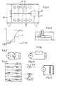
- Figure 1 shows an example of direct coupling of a bulb wind turbine 1 mounted on the support rods 2 made integral with the receiving shaft 3 which is coupled directly to the generator 4 by means of a rigid sleeve 5.
- the shaft 3 is held on the frame 6 by the ball bearing 7.
- a sealed cover 8 protects the generator from the weather.
- the sole 9 is fixed to the top of a post.
- FIG. 2 shows an example of a bulb wind turbine 10 submerged parallel to the water body 11.
- the receiving shaft is placed vertically upwards and coupled to the electric generator 12, made integral with a float 13 by a frame rigid 14 on which is fixed a cowling 15.
- the chassis 14 has the feet 15 provided to prevent the bulbs from rubbing against the bottom of the river during a significant drop in level.
- FIG. 3 schematically represents a bulb wind turbine used in a water mill, whether or not coupled to an electric generator.
- the bulbs are arranged on a plane perpendicular to the water body 16 and driven in rotation by the fig current. by arrow 17.
- Figure 4 there is shown the top view showing 5 rows of bulbs 18 secured to the same receiving shaft 19 coupled to the electric generator 20 fixed on a frame secured to the floats 21,22 which are secured between them and anchored to the ground.
- the bulbs are offset so that there is always at least one that receives the thrust of the water so as to ensure the regularity of the couple.
- Load switching can be carried out electromechanically from a detector of variation of the output voltage across the generator supplying a static or electromechanical electronic programmer relaying the supply of loads.
- FIG. 6 shows an example of an electronic diagram for controlling the progressive variation of the power of a single-phase current generator by phase shift, in which the detector D of variation of the voltage across the terminals of the generator drives a conformator C which transforms the alternating voltage into pulses attacking the "trigger" of the triac T or 2 thyristors.
- a single detector D is enough for a polyphase machine.
- FIG. 7 shows an example of a DC generator diagram in which the progressive variation of the power is obtained by one or more thyristors
- FIG. 8 shows the example of another control diagram of a direct current generator on which the variation of the power is obtained by means of a current chopper H.
- FIG. 9 shows an example of a single-phase alternating current generator diagram with power variation in stages. It comprises, according to the invention, the charges L1, L2, L3, the thresholds of voltage levels S1, S2, S3, defining three power levels and attacking "the trigger" of triacs or thyristors or any other means capable of 'ensure the connection of loads such as for example the static contactor of Figure 10 or that of Figure 11 well known to those skilled in the art. It is also possible to switch on the loads by means of an electromechanical programmer powered by a detector for variation of the output voltage at the terminals of the generator comprising three thresholds defining the power steps.
- FIG. 12 a simplified diagram of a generator is shown, the power of which is adapted by a set of "non-linear" loads constituted for example by a series of silicon diodes whose heat losses constitute the available energy usable by example for heating a heat transfer fluid.
Abstract
Description
Convertisseur d'énergie fluidique en énergie électrique ou mécanique, comportant un récepteur mécanique constitué par une éolienne constituée par au moins trois bulbes hémisphériques disposés sur un même plan et fixés chacun sur une tige métallique support solidaire d'un arbre récepteur et coopérant avec une génératrice de courant électrique.Fluidic energy to electrical or mechanical energy converter, comprising a mechanical receiver constituted by a wind turbine constituted by at least three hemispherical bulbs arranged on the same plane and each fixed on a metal support rod secured to a receiving shaft and cooperating with a generator of electric current.
On connait un convertisseur de ce type décrit dans le brevet français n° 78 26938. Ce convertisseur éolien à bulbesà axe vertical est accouplé à une génératrice de courant électrique par l'intermédiaire d'un multiplicateur de vitesse du fait que la vitesse de rotation de ce type d'éolienne est faible comparativement aux éoliennes à axe horizontal. Il en résulte une opération d'entretien supplémentaire et un accroissement du coût.We know a converter of this type described in French patent n ° 78 26938. This wind turbine converter with vertical axis bulbs is coupled to an electric current generator by means of a speed multiplier because the rotation speed of this type of wind turbine is low compared to horizontal axis wind turbines. This results in an additional maintenance operation and an increase in cost.
La présente invention a pour but de pallier ces inconvénients. L'invention telle qu'elle est caractérisée dans les revendications résoud le problème consistant à supprimer le multiplicateur de vitesse attaquant l'arbre d'entrée de la génératrice en accouplant directement celui-ci sur l'arbre récepteur de l'éolienne. Du fait de la faible vitesse de rotation, le couple résistant de la génératrice est élevé et nécessite normalement un couple de démarrage important . Pour pallier cet inconvénient, la courbe de puissance de la génératrice est ajustée par un moyen annexe électromécanique ou electronique agissant par rapporL a la courbe couple-vitesse de l'arbre récepteur de façon progressive ou par paliers successifs depuis le couple de démarrage jusqu'à la puissance maximale de ladite génératrice.The present invention aims to overcome these drawbacks. The invention as characterized in the claims solves the problem of eliminating the speed multiplier attacking the input shaft of the generator by directly coupling it on the receiving shaft of the wind turbine. Due to the low speed, the resistive torque of the generator is high and normally requires a large starting torque. To overcome this drawback, the power curve of the generator is adjusted by an electromechanical or electronic auxiliary means acting in relation to the torque-speed curve of the receiving shaft progressively or in successive stages from the starting torque to the maximum power of said generator.
Les avantages obtenus grâce à cette invention sont les suivants:
- - réduction notable du coût de revient et du coût d'entretien donc réduction de la durée d'amortissement par un faible coût du KW installé;
- - accroissement de la fiabilité par réduction de la quantité d'organes en mouvement et par la réduction importante de la vitesse de rotation de la génératrice. Il en résulte un allongement de la durée entre les opérations d'entretien et une bien plus grande longévité.
- - Fonctionnement assuré sans risque de détérioration même par tempête par limitation de la puissance maximale;
- -démarrage obtenu même à faible vitesse du vent;
- - utilisation possible au fil de l'eau de façon analogue à un moulin à eau ou immergé le plan des bulbes parallèle au plan d'eau du fait de la faible vitesse nécessaire à la génératrice.
- - significant reduction in the cost price and maintenance cost therefore reduction of the depreciation period by a low cost of the installed KW;
- - Increased reliability by reducing the quantity of moving parts and by significantly reducing the speed of rotation of the generator. This results in an extension of the time between maintenance operations and a much greater longevity.
- - Operation guaranteed without risk of deterioration even by storm by limiting the maximum power;
- -starting obtained even at low wind speed;
- - possible use over the water in a similar way to a water mill or submerged the plane of the bulbs parallel to the water due to the low speed required for the generator.
L'invention est décrite plus en détail dans la description qui suit, faite en référence aux dessins annexés dans lesquels :
- - la figure 1 montre, vu en coupe en élévation, un exemple de couplage direct selon l'invention d'une éolienne à bulbe avec une génératrice électrique,
- - la figure 2 montre un exemple de convertisseur selon l'invention immergé parallèlement au plan d'eau,
- - la figure 3 montre un exemple d'éolienne utilisée en moulin à eau,
- - la figure 4 montre l'éolienne de la fig.3 en vue de dessus,
- - la figure 5 montre les courbes de variation progressive et par paliers de la puissance de la génératrice,
- - la figure 6 montre un exemple de schéma électronique de commande de variation progressive de puissance pour une génératrice monophasée,
- - les figures 7 et 8 montrent 2 exemples de commande de variation progressive de la puissance pour des génératrices à courant continu,
- - la figure 9 représente un exemple de variation de puissance par paliers pour une machine à courant monophasé,
- - les figures 10 et 11 montrent schématiquement des exemples de connection de résistances de charge,
- - la figure 12 montre un exemple de schéma de commande de variation progressive de la puissance au moyen de résistances de charge non linéaires.
- FIG. 1 shows, seen in section in elevation, an example of direct coupling according to the invention of a bulb wind turbine with an electric generator,
- FIG. 2 shows an example of a converter according to the invention immersed parallel to the water,
- FIG. 3 shows an example of a wind turbine used in a water mill,
- - Figure 4 shows the wind turbine of fig.3 in top view,
- FIG. 5 shows the curves of progressive and stepwise variation of the power of the generator,
- FIG. 6 shows an example of an electronic diagram for controlling progressive variation of power for a single-phase generator,
- FIGS. 7 and 8 show 2 examples of control of progressive variation of the power for direct current generators,
- FIG. 9 represents an example of power variation in stages for a single-phase current machine,
- FIGS. 10 and 11 schematically show examples of connection of load resistors,
- - Figure 12 shows an example of a control scheme for progressive variation of the power by means of non-linear load resistors.
La figure 1 montre un exemple d'accouplement direct d'une éolienne à bulbes 1 montés sur les tiges supports 2 rendues solidaires de l'arbre récepteur 3 lequel est accouplé directement sur la génératrice 4 au moyen d'un manchon rigide 5. L'arbre 3 est maintenu sur le bâti 6 par le roulement à billes 7. Un capot étanche 8 protège la génératrice des intempéries. La semelle 9 est fixée au sommet d'un poteau.Figure 1 shows an example of direct coupling of a
La figure 2 montre un exemple d'éolienne à bulbes 10 immergée parallèlement au plan d'eau 11. L'arbre récepteur se trouve disposé verticalement vers le haut et accouplé à la génératrice électrique 12, rendue solidaire d'un flotteur 13 par un châssis rigide 14 sur lequel est fixé un capotage 15. Le châssis 14 comporte les pieds 15 prévus pour éviter que les bulbes frottent sur le fond de la rivière lors d'une importante baisse de niveau.FIG. 2 shows an example of a
La figure 3 représente schématiquement une éolienne à bulbes utilisée en moulin à eau accouplée ou non à une génératrice électrique. Les bulbes sont disposés sur un plan perpendiculaire au plan d'eau 16 et entrainés en rotation par le courant figu. par la flèche 17. Sur la figure 4 on a représenté la vue de dessus montrant 5 rangées de bulbes 18 solidaires d'un même arbre récepteur 19 accouplé à la génératrice électrique 20 fixée sur un châssis solidaire des flotteurs 21,22 lesquels sont assujettis entre eux et ancrés au sol. Les bulbes sont décalés de telle sorte qu'il y en a toujours au moins un qui reçoit la poussée de l'eau de façon à assurer la régularité du couple.FIG. 3 schematically represents a bulb wind turbine used in a water mill, whether or not coupled to an electric generator. The bulbs are arranged on a plane perpendicular to the
La figure 5 montre un exemple de courbe couple-vitesse d'une éolienne à bulbes. Le point S représente le seuil de démarrage de la génératrice qui a un couple résistant important. Le point M représente la puissance maximale de la génératrice. Pour pouvoir recueillir l'énergie du vent ou de l'eau à faible vitesse, on ajuste la courbe de puissance de la génératrice de courant électrique sur cette courbe au moyen d'une charge que l'on fait varier pour suivre cette courbe soit progressivement, soit par paliers (courbe P). Au démarrage, au point S, la charge est faible, elle s'accroît au fur et à mesure de l'accroissement de la vitesse de rotation de l'arbre récepteur (courbe R). Il existe de nombreux moyens connus pour faire varier cette puissance selon le type de génératrice, soit à courant continu, soit à courant alternatif mono ou polyphasé. On peut par exemple laisser l'éolienne tourner librement jusqu'au point S et accoupler la génératrice au moyen d'un coupleur centrifuge à poudre ou à masselottes ou encore à courant de foucault. On peut également utiliser un simple embrayage électromagnétique. A partir du point S on peut utiliser un ensemble de résistances de charge connectées en tout-ou-rien par divers moyens connus de l'homme de l'art, sélectionnées en fonction des niveaux de tension de la génératrice de courant pour accroître la charge au fur et à mesure de la croissance des couple-vitesse de l'arbre récepteur. La variation peut être obtenue selon la loi d'Ohm 1 = u de la façon suivante :
- 1 - Variation progressive de la tension U
- . Obtenue par déphasage :
- - machine à courant monophasé (fig.6)
- - machine à courant polyphasé
- . Obtenue par hacheur de courant (fig.8)
- . Obtenue par transistors ou composants similaires (fig.7)
- - machine à courant continu
- . Obtenue par déphasage :
- 2 - Variation de la puissance par paliers successifs
- . Obtenue par la mise en circuit ou hors circuit séquentielle des résistances de charge
- - machines monophasées, polyphasées ou à courant continu (fig.9,10 et 11).
- . Obtenue par la mise en circuit ou hors circuit séquentielle des résistances de charge
- 1 - Progressive variation of voltage U
- . Obtained by phase shift:
- - single-phase machine (fig. 6)
- - polyphase current machine
- . Obtained by current chopper (fig. 8)
- . Obtained by transistors or similar components (fig. 7)
- - DC machine
- . Obtained by phase shift:
- 2 - Variation of power in successive steps
- . Obtained by switching the load resistors on or off sequentially
- - single-phase, multi-phase or direct current machines (fig. 9,10 and 11).
- . Obtained by switching the load resistors on or off sequentially
La mise en circuit des charges peut être effectuée de façon électromécanique à partir d'un détecteur de variation de la tension de sortie aux bornes de la génératrice alimentant un programmateur électronique statique ou électromécanique relayant l'alimentation des charges. On a montré sur la figure 6 un exemple de schéma électronique de commande de variation progressive de la puissance d'une génératrice de courant monophasé par déphasage, dans lequel le détecteur D de variation de la tension aux bornes de la génératrice attaque un conformateur C qui transforme la tension alternative en impulsions attaquant la "gachette" du triac T ou de 2 thyristors.Pour une machine polyphasée, il suffit de répéter le même schéma pour chacune des phases, un seul détecteur D suffit.Load switching can be carried out electromechanically from a detector of variation of the output voltage across the generator supplying a static or electromechanical electronic programmer relaying the supply of loads. FIG. 6 shows an example of an electronic diagram for controlling the progressive variation of the power of a single-phase current generator by phase shift, in which the detector D of variation of the voltage across the terminals of the generator drives a conformator C which transforms the alternating voltage into pulses attacking the "trigger" of the triac T or 2 thyristors. For a polyphase machine, it is enough to repeat the same diagram for each of the phases, a single detector D is enough.
La figure 7 montre un exemple de schéma de génératrice à courant continu dans lequel la variation progressive de la puissance est obtenue par un ou plusieurs thyristorsFIG. 7 shows an example of a DC generator diagram in which the progressive variation of the power is obtained by one or more thyristors
La figure 8 montre l'exemple d'un autre schéma de commande d'une génératrice à courant continu sur lequel la variation de la puissance est obtenue au moyen d'un hacheur de courant H.FIG. 8 shows the example of another control diagram of a direct current generator on which the variation of the power is obtained by means of a current chopper H.
La figure 9 montre un exemple de schéma de génératrice de courant alternatif monophasé à variation de puissance par paliers. Il comporte,.selon l'invention , les charges L1, L2, L3, les seuils de niveaux de tension S1,S2,S3, définissant trois paliers de puissance et attaquant "la gachette" de triacs ou thyristors ou tout autre moyen susceptible d'assurer la connection des charges tels que par exemple le contacteur statique de la figure 10 ou celui de la figure 11 bien connus de l'homme de l'art. On peut également effectuer la mise en circuit des charges au moyen d'un programmateur électromécanique alimenté par un détecteur de variation de la tension de sortie aux bornes de la génératrice comportant trois seuils définissant les paliers de puissance.FIG. 9 shows an example of a single-phase alternating current generator diagram with power variation in stages. It comprises, according to the invention, the charges L1, L2, L3, the thresholds of voltage levels S1, S2, S3, defining three power levels and attacking "the trigger" of triacs or thyristors or any other means capable of 'ensure the connection of loads such as for example the static contactor of Figure 10 or that of Figure 11 well known to those skilled in the art. It is also possible to switch on the loads by means of an electromechanical programmer powered by a detector for variation of the output voltage at the terminals of the generator comprising three thresholds defining the power steps.
Sur la figure 12, on a représenté un schéma simplifié d'une génératrice dont la puissance est adaptée par un ensemble de charges "non linéaires" constituées par exemple par une série de diodes au silicium dont les pertes calorifiques constituent l'énergie disponible utilisable par exemple pour chauffer un fluide caloporteur.In FIG. 12, a simplified diagram of a generator is shown, the power of which is adapted by a set of "non-linear" loads constituted for example by a series of silicon diodes whose heat losses constitute the available energy usable by example for heating a heat transfer fluid.
Ces divers blocs électroniques de variation de puissance sont prévues en cas de tempête, pour éviter le dépassement de la puissance maximale de la génératrice en faisant varier dégressivement la résistance de charge en rapport avec la croissance de la vitesse de l'arbre récepteur de l'éolienne.These various electronic power variation blocks are provided in the event of a storm, to avoid exceeding the maximum power of the generator by gradually decreasing the load resistance in relation to the growth of the speed of the receiving shaft of the wind turbine.
Claims (9)
Applications Claiming Priority (2)
| Application Number | Priority Date | Filing Date | Title |
|---|---|---|---|
| FR8011498A FR2483016A1 (en) | 1980-05-23 | 1980-05-23 | KINETIC ENERGY CONVERTER OF FLUIDS IN ELECTRIC OR MECHANICAL ENERGY |
| FR8011498 | 1980-05-23 |
Publications (1)
| Publication Number | Publication Date |
|---|---|
| EP0041011A1 true EP0041011A1 (en) | 1981-12-02 |
Family
ID=9242261
Family Applications (1)
| Application Number | Title | Priority Date | Filing Date |
|---|---|---|---|
| EP81400784A Withdrawn EP0041011A1 (en) | 1980-05-23 | 1981-05-19 | Fluid current driven machine generating electric or mechanical power |
Country Status (2)
| Country | Link |
|---|---|
| EP (1) | EP0041011A1 (en) |
| FR (1) | FR2483016A1 (en) |
Cited By (1)
| Publication number | Priority date | Publication date | Assignee | Title |
|---|---|---|---|---|
| WO2005098233A1 (en) * | 2004-04-08 | 2005-10-20 | Alfred Learmonth | W.w. generator |
Citations (10)
| Publication number | Priority date | Publication date | Assignee | Title |
|---|---|---|---|---|
| BE669697A (en) * | ||||
| US2579311A (en) * | 1948-03-05 | 1951-12-18 | Fairey Charles Richard | Wind-driven power generator |
| FR1460787A (en) * | 1964-10-16 | 1966-01-07 | Honeywell Inc | Device for transferring electrical energy from a source to a load |
| CH437490A (en) * | 1960-12-30 | 1967-06-15 | Bbc Brown Boveri & Cie | Electrical system with at least one power generation unit, which has a turbine and a generator with strongly fluctuating speed |
| FR2266006A2 (en) * | 1973-01-16 | 1975-10-24 | Clausin Jacques | |
| US3942025A (en) * | 1974-04-22 | 1976-03-02 | Zaisui Ri | Process for storing electricity for a fast advancing conveyance and device for storing such electricity |
| DE2446980A1 (en) * | 1974-10-02 | 1976-04-15 | Weineck Albert Hans Joachim | Water wheel for electric power generation - has impeller in longitudinal sections suspended to float in stream |
| FR2384963A1 (en) * | 1977-03-25 | 1978-10-20 | Voukourakos Constantin | Wind driven electrical generator for domestic use - has anemometer type impeller in horizontal plane on vertical shaft which supports rotor of generator with permanent magnetic field |
| FR2436890A1 (en) * | 1978-09-20 | 1980-04-18 | Foa Michel | VERTICAL AXIS WIND TURBINE |
| US4200833A (en) * | 1977-10-31 | 1980-04-29 | Wilkerson A W | Power maximization circuit |
-
1980
- 1980-05-23 FR FR8011498A patent/FR2483016A1/en active Granted
-
1981
- 1981-05-19 EP EP81400784A patent/EP0041011A1/en not_active Withdrawn
Patent Citations (10)
| Publication number | Priority date | Publication date | Assignee | Title |
|---|---|---|---|---|
| BE669697A (en) * | ||||
| US2579311A (en) * | 1948-03-05 | 1951-12-18 | Fairey Charles Richard | Wind-driven power generator |
| CH437490A (en) * | 1960-12-30 | 1967-06-15 | Bbc Brown Boveri & Cie | Electrical system with at least one power generation unit, which has a turbine and a generator with strongly fluctuating speed |
| FR1460787A (en) * | 1964-10-16 | 1966-01-07 | Honeywell Inc | Device for transferring electrical energy from a source to a load |
| FR2266006A2 (en) * | 1973-01-16 | 1975-10-24 | Clausin Jacques | |
| US3942025A (en) * | 1974-04-22 | 1976-03-02 | Zaisui Ri | Process for storing electricity for a fast advancing conveyance and device for storing such electricity |
| DE2446980A1 (en) * | 1974-10-02 | 1976-04-15 | Weineck Albert Hans Joachim | Water wheel for electric power generation - has impeller in longitudinal sections suspended to float in stream |
| FR2384963A1 (en) * | 1977-03-25 | 1978-10-20 | Voukourakos Constantin | Wind driven electrical generator for domestic use - has anemometer type impeller in horizontal plane on vertical shaft which supports rotor of generator with permanent magnetic field |
| US4200833A (en) * | 1977-10-31 | 1980-04-29 | Wilkerson A W | Power maximization circuit |
| FR2436890A1 (en) * | 1978-09-20 | 1980-04-18 | Foa Michel | VERTICAL AXIS WIND TURBINE |
Cited By (1)
| Publication number | Priority date | Publication date | Assignee | Title |
|---|---|---|---|---|
| WO2005098233A1 (en) * | 2004-04-08 | 2005-10-20 | Alfred Learmonth | W.w. generator |
Also Published As
| Publication number | Publication date |
|---|---|
| FR2483016B1 (en) | 1984-05-25 |
| FR2483016A1 (en) | 1981-11-27 |
Similar Documents
| Publication | Publication Date | Title |
|---|---|---|
| EP1362184B1 (en) | Method and device for regulating a wind machine | |
| EP2494184A2 (en) | Turbine engine starter/generator, and method for the control thereof | |
| EP2721728A2 (en) | Alternator with voltage regulation | |
| EP0783201A1 (en) | Synchronous type electric motor and vehicle equipped with such a motor | |
| FR2474781A1 (en) | CONVERTER GROUP COMPRISING A THREE-PHASE MOTOR AND A SYNCHRONOUS GENERATOR | |
| EP1935087A1 (en) | Electromechanical driving system, in particular for progressive cavity pump for oil well | |
| EP0002981A1 (en) | Method and apparatus for regulating the voltage of an electrical generator | |
| EP0041011A1 (en) | Fluid current driven machine generating electric or mechanical power | |
| CA1246702A (en) | Liquid resistance rheostat with electrolyte circulator | |
| EP2380261B1 (en) | Self switched photovoltaic motor | |
| FR2561718A1 (en) | LOW FALL HYDROELECTRIC INSTALLATION | |
| EP0054446B1 (en) | Electric asynchronous motor, means for controlling the feeding of such a motor and circulating drive comprising such a motor | |
| FR2986917A1 (en) | ELECTRIC POWER SUPPLY SYSTEM AND ELECTRIC POWER GENERATION PLANT COMPRISING SUCH A SYSTEM | |
| EP0091869B1 (en) | Pumping unit such as a circulator for a central-heating installation with a predetermined hydraulic calibration line | |
| FR2517490A1 (en) | ASYNCHRONOUS MOTOR WITH ROTOR SHORT CIRCUIT AND POLES SWITCHING | |
| FR2502420A1 (en) | ROTATION SPEED VARIATION CONTROL CIRCUIT OF A SINGLE-PHASE INDUCTION MOTOR | |
| EP0044244A2 (en) | Single-phase induction motor | |
| FR2551142A1 (en) | Heating and/or air conditioning installation using mechanical energy gathered on the shaft of a wind-power engine rotating at variable speed | |
| FR2539564A1 (en) | Supply and load matching circuit for AC motor | |
| FR2465361A1 (en) | RECOVERY DIRECT CURRENT CONTROLLED SUPPLY CIRCUIT | |
| FR2513038A1 (en) | Starting circuit for single phase async. motor - uses triac in series with auxiliary winding with coil of reed relay in principal winding to switch off triac when current is established | |
| FR2478399A1 (en) | CONTROL SYSTEM FOR INDUCTION ALTERNATIVE MOTORS | |
| GB2092237A (en) | Means for Converting Natural Fluid Energy into Electrical or Mechanical Energy | |
| FR2781319A1 (en) | VOLTAGE REGULATOR FOR A PERMANENT MAGNET ALTERNATOR | |
| EP3204964B1 (en) | Photovoltaic-effect transistor and connected photovoltaic motor having increased power |
Legal Events
| Date | Code | Title | Description |
|---|---|---|---|
| PUAI | Public reference made under article 153(3) epc to a published international application that has entered the european phase |
Free format text: ORIGINAL CODE: 0009012 |
|
| AK | Designated contracting states |
Designated state(s): BE CH DE IT NL SE |
|
| 17P | Request for examination filed |
Effective date: 19820524 |
|
| STAA | Information on the status of an ep patent application or granted ep patent |
Free format text: STATUS: THE APPLICATION IS DEEMED TO BE WITHDRAWN |
|
| 18D | Application deemed to be withdrawn |
Effective date: 19830630 |