EP2380261B1 - Self switched photovoltaic motor - Google Patents
Self switched photovoltaic motor Download PDFInfo
- Publication number
- EP2380261B1 EP2380261B1 EP10707324.9A EP10707324A EP2380261B1 EP 2380261 B1 EP2380261 B1 EP 2380261B1 EP 10707324 A EP10707324 A EP 10707324A EP 2380261 B1 EP2380261 B1 EP 2380261B1
- Authority
- EP
- European Patent Office
- Prior art keywords
- motor
- photovoltaic
- mask
- stator
- cell
- Prior art date
- Legal status (The legal status is an assumption and is not a legal conclusion. Google has not performed a legal analysis and makes no representation as to the accuracy of the status listed.)
- Active
Links
Images


Classifications
-
- H—ELECTRICITY
- H02—GENERATION; CONVERSION OR DISTRIBUTION OF ELECTRIC POWER
- H02K—DYNAMO-ELECTRIC MACHINES
- H02K29/00—Motors or generators having non-mechanical commutating devices, e.g. discharge tubes or semiconductor devices
- H02K29/06—Motors or generators having non-mechanical commutating devices, e.g. discharge tubes or semiconductor devices with position sensing devices
- H02K29/10—Motors or generators having non-mechanical commutating devices, e.g. discharge tubes or semiconductor devices with position sensing devices using light effect devices
-
- H—ELECTRICITY
- H02—GENERATION; CONVERSION OR DISTRIBUTION OF ELECTRIC POWER
- H02K—DYNAMO-ELECTRIC MACHINES
- H02K11/00—Structural association of dynamo-electric machines with electric components or with devices for shielding, monitoring or protection
- H02K11/0094—Structural association with other electrical or electronic devices
-
- H—ELECTRICITY
- H02—GENERATION; CONVERSION OR DISTRIBUTION OF ELECTRIC POWER
- H02K—DYNAMO-ELECTRIC MACHINES
- H02K11/00—Structural association of dynamo-electric machines with electric components or with devices for shielding, monitoring or protection
- H02K11/30—Structural association with control circuits or drive circuits
- H02K11/33—Drive circuits, e.g. power electronics
-
- H—ELECTRICITY
- H02—GENERATION; CONVERSION OR DISTRIBUTION OF ELECTRIC POWER
- H02K—DYNAMO-ELECTRIC MACHINES
- H02K3/00—Details of windings
- H02K3/04—Windings characterised by the conductor shape, form or construction, e.g. with bar conductors
- H02K3/28—Layout of windings or of connections between windings
Definitions
- the present invention relates to a self-contained photovoltaic motor. More particularly, the subject of the present invention is a self-commutated variable reluctance machine for supplying electric current to the phases of the motor.
- FIG. 1 shows a DC permanent magnet motor 10.
- the motor 10 comprises a stator 11 with two poles with permanent magnets and a rotor 12 comprising windings.
- the motor 10 is powered by a photovoltaic generator 15.
- the motor 10 comprises a mechanical switching device formed by a collector 13 and a brush holder 14.
- the collector 13 is connected to the windings and integral with the axis of the motor 10.
- the collector 13 and the brushes 14 can successively switch the current in the different windings of the rotor.
- the figure 2 shows another example of the engine 20 of the state of the art, said brushless.
- the motor 20 comprises a rotor 22 with a permanent magnet and a stator 21 comprising windings.
- the rotor 22 is fixed on the motor shaft 20.
- the motor 20 is powered by a photovoltaic generator 25.
- the motor 20 comprises an electronic switching device formed of a sensor 23 associated with an electronic control 24.
- the control electronics 24 switches the current in the windings according to the position of the rotor 22 determined by the sensor 23.
- the mechanical switch of the figure 1 here is replaced by a power electronics associated with a sensor.
- the main disadvantage of the motor 20 described in figure 2 is to require more complicated electronics because of a polyphase power supply. As a result, the price of the electronics added to that of the motor is generally higher than the DC motor of the figure 1 .
- the use of a position sensor has servo disadvantages due mainly to its accuracy of wedging.
- the figure 3 shows another example of asynchronous or other alternative AC motors of the state of the art.
- the motor 30 comprises a stator 31 comprising windings and connected to a converter 33 for transforming the direct current supplied by a photovoltaic generator into alternating current.
- the motor 30 comprises a rotor 32 consisting of short-circuited conductors which are traversed by currents induced by the magnetic field created by the stator currents.
- this alternative motor has disadvantages. Indeed, because the photovoltaic generator delivers only DC current, it is then necessary to interpose, between the coils of the motor 20 and the generator 35, an electronic device comprising a converter or inverter and an electronic control circuit. more complex than those of the DC motors described in Figures 1 and 2 .
- the document US-A-4,634,343 discloses a self-contained photovoltaic motor comprising photovoltaic cells and a mask, driven by the movable shaft, and comprising four switching apertures.
- the invention proposes a self-contained photovoltaic motor requiring no magnet, no switching device and no converter.
- each coil of the invention is directly connected to a photovoltaic cell.
- the cells are arranged around the engine.
- a mask is placed on the motor shaft. This mask has transparent parts and opaque parts. During the rotation of the motor, the photovoltaic cells located under the transparent parts feed the motor. The mask makes it possible to obtain a self-managed photovoltaic motor without any intermediate device between the coils and the cells.
- the invention also relates to a system in which is installed a self-commutated photovoltaic motor variable reluctance according to the invention.
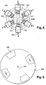
- the figure 4 shows a stepping motor comprising the improved means of the invention.
- the improved means of the invention are applied to a motor 100 with variable reluctance.
- the motor 100 with variable reluctance is undoubtedly the simplest electric motor that can be realized.
- the operation of this motor 100 is independent of the direction of the current; there is no polarity to respect.
- the direction of rotation does not depend on the direction of the current but on the order of supply of the coils of the motor 100.
- the motor 100 comprises a rotor 101.
- the rotor 101 is a non-magnetized cylinder in which are cut teeth that are poles 102 of the rotor 101.
- the movement of the rotor 101 is independent of the direction of supply of the different phases of the motor: the choosing the feed sequence determines its direction of rotation.
- the poles 102 of the rotor 101 are positioned in the direction of the weakest reluctance. In the example of the figure 4 the rotor 101 has four poles 102.
- the motor 100 comprises a stator 103.
- the stator 103 is preferably a stack of cut sheets to reduce eddy currents, notches where are housed coils 104.
- the rotor 101 is a stack of sheets as the stator 103.
- the sheets are preferably of silicon iron.
- the rotor and the stator can be made of solid soft iron, particularly when the motor is slow.
- the stator 103 has six notches 109a. These notches 109a are delimited alternately by teeth 109b of the stator 103 each receiving a coil 104.
- the teeth 109b of the coils 104 are 30 degrees from each other.
- phase AA ' corresponds to the supply of both the coil A and the coil A' and so on.
- the rotor 101 has fewer poles than there are teeth to the stator 103.
- the poles 102 of the rotor 101 are placed in such a way that the flux passing through them is maximum (or minimum reluctance).
- a coil 104 when energized, it attracts a pole 102 of the nearest rotor 101 so that the kissed flux is maximum.
- the poles 102 of the rotor 101 are positioned between the notches 109a of the energized coils 104.
- the rotor 101 thus advances one step at each current pulse on a new pair of spools 104. Feeding a pair of coils at the same time provides high torque to the motor 100.
- each of them is connected to a photovoltaic cell 105.
- the photovoltaic cells 105 are arranged all around the stator 103.
- the photovoltaic cells 105 are arranged in a circular manner around the stator 103. They are arranged relative to one another according to the arrangement of the notches 109a. In the example of the figure 5 they are 60 degrees from each other in a ring around the stator 103.
- the invention proposes to successively switch the supply of the coils without using an electronic control circuit or mechanical switch.
- an alignment mask 106 is disposed on the photovoltaic cells 105, as shown in FIG. figure 5 .
- This mask 106 has a surface capable of covering the photovoltaic cells 105.
- the mask 106 is mounted on a shaft 107 of the motor 100. The mask 106 is thus secured to the rotor 101. The alignment mask 106 is positioned relative to the photovoltaic cells 105.
- the mask 106 is a light-opaque disk having apertures 108 capable of passing light.
- the openings 108 may be holes made on the mask 106.
- the mask 106 may be a succession of opaque material and transparent material forming the openings 108.
- the mask 106 has four openings 108. These openings 108 are arranged in diametrically opposed pairs. They are arranged on the mask 106 so as to align a pair of openings 108 with the photovoltaic cells 105 of a pair of coils 104. The openings 108 are arranged on the mask 106 so that a single pair photovoltaic cells 105 of a pair of coils 104 are fed at a time. In the example of the figure 5 the openings 108 are at 90 degrees from each other.
- the mask 106 is made of a sealing material preferably sealed.
- a control pulse is applied to the motor 100 so as to advance the rotor 101 by a step of 30 degrees.
- This movement of the rotor 101 causes the rotation of the mask 106 and the illumination of the photovoltaic cells 105 of the next pair of coils 104.
- the rotation of the motor 100 successively unmasks the cells 105 in pairs.
- the mask 106 thus acts as an optical switch where the movement of the rotor 101 is obtained by illuminating, in turn, the photovoltaic cells 105 of a pair of poles of the stator 103.
- FIG. 6 shows an embodiment of the invention where the available mechanical power is doubled compared to that of the figure 5 .
- the motor 100 comprises secondary photovoltaic cells 110.
- Each primary photovoltaic cell 105 is connected in series with a secondary photovoltaic cell 110.
- the secondary photovoltaic cells 110 are arranged on empty spaces between the primary cells 105. They are placed at 30 degrees of two successive primary cells 105.
- a secondary cell 110 is placed on the ring relative to the primary photovoltaic cell 105, which it is connected in series, so as to allow its illumination when said primary cell is illuminated.
- the position of this secondary cell 110 on the ring relative to the primary cell 105 to which it is connected in series depends on the arrangement of the openings 108 on the mask 106.
- the secondary cell 110 is at 90 degrees with respect to the primary photovoltaic cell 105 of which it is connected in series.
- the cells 110 added to the empty spaces are connected to a second motor integral with the shaft 107 of the first motor 100.
- everything passes as if there were two rings of independent cells.
- the mechanical power is doubled; at the price, however, of greater mechanical complexity.
- the figure 7 shows another variant to increase the available mechanical power.
- the motor 100 is powered by at least one fixed cell 111.
- the fixed cell 111 has a surface much larger than that of the photovoltaic cells 105 of the figure 5 .
- This fixed cell 111 is constantly illuminated.
- the fixed cell 111 is connected in series with at least one photovoltaic cell 105.
- the coils 104 are connected to the fixed cell 111 through the corresponding photovoltaic cells 105.
- a blind cell 105 is comparable to an open circuit.
- the cells 105 can be used not only as cyclic current generators, but also as switches interposed between the coils and the cell 111 of large area constantly illuminated.
- the energy of the fixed cell 111 circulates in said photovoltaic cell 105 only when the latter is illuminated. In this case, the power of the motor 100 is increased only when said photovoltaic cell 105 is switched.
- the fixed cell 111 is connected to one of the coils 104 of all the pairs of coils of the motor 100. Therefore, each time a pair of cells is illuminated, the power of the motor 100 is increased. To double this power of the motor 100, it is provided in the example of the figure 7 connecting the other pair of the coils 104 of all the pairs of coils, free, to another fixed cell 112. In the example of the figure 7 the coils A, B and C 'are connected to the fixed cell 111 and the coils C, A' and B 'are connected to the other fixed cell 112.
- the two main advantages of the autocommuted photovoltaic motor of the invention are its simplicity of construction and its absence of wear. Indeed, provided that the motor is equipped with quality ball bearings, its lifetime is equivalent to that of photovoltaic cells 105; that is to say, today, about twenty to twenty-five years.
- such an engine can be used to raise water from wells dug in areas where the sun is abundant. Not only does the engine not require maintenance, but the disc pierced with windows made of transparent material ensures protection of the cells against the sand. Indeed, the photovoltaic cells are protected by the closing mask which forms a tight cover. In addition, the rotation of the disc, ejecting the sand that naturally deposits on its surface, ensures a constant performance over time.
- the motor of the invention is also advantageous for the equipment of a greenhouse. Indeed, the motor shaft, fixed above the roof, directly drives the blades of a turbine placed inside the greenhouse. This device provides economic ventilation which is all the more effective as the solar radiation is intense; that is to say precisely when the temperature of the greenhouse is the highest.
- Air extractors comprising the photovoltaic engine of the invention can be mounted on trucks whose cargo requires forced ventilation. This is, for example, the case when transporting animals. With the advantage that at a standstill, in full sun, photovoltaic engine air extractors operate without exhausting the vehicle's battery.
- the motor of the invention can also be used in collective microfabrication processes which make it possible to produce submillimeter-sized motors.
- it is the variable reluctance machine that has given rise to the greatest number of achievements.
- photovoltaic cells are also devices resulting from the manufacturing processes of electronic components. So, we can realize an engine by etching on the same silicon substrate a variable reluctance micromotor and photovoltaic cells. If, in addition, the cells are illuminated by means of a fiber optic strand, this motor operates without external power supply.
- Such an engine finds its application in explosive environments where any risk of spark is banned.
- the invention is not limited to the embodiments shown in the figures. In particular, the invention can also be applied to hybrid engines.
- the number of openings of a mask is not limited to four. It can be greater or less than four depending on the type of engine to be powered and the desired mechanical power.
- the number of rotor poles and the stator is given only as examples.
- the motor of the invention may further comprise means for cleaning the photovoltaic cells.
- These cleaning means may be a broom installed on the mask on one side in contact with the photovoltaic cells.
- These cleaning means may also be a flush glass placed at the openings of the mask.
- the motor can be inclined with respect to a horizontal plane. This inclination of the motor also makes it possible to best direct the photovoltaic cells towards the sun, which is not always vertical to the place where the motor is installed.
- the dimensions of the switched photovoltaic cells and possibly of the fixed cell depend on the desired mechanical power.
- the different elements of the motor are dimensioned with respect to the desired power and the surface of the cells.
- the invention thus makes it possible to use an electric motor without electrical or mechanical switching.
- the engine of the invention thus makes it possible to reduce the overall maintenance costs and the cost price of an electric motor, while maintaining the level of performance of said engine.
Description
La présente invention a pour objet un moteur photovoltaïque autocommuté. Plus particulièrement, la présente invention a pour objet une machine à reluctance variable autocommutée pour l'alimentation en courant électrique des phases du moteur.The present invention relates to a self-contained photovoltaic motor. More particularly, the subject of the present invention is a self-commutated variable reluctance machine for supplying electric current to the phases of the motor.
Actuellement il existe des moteurs électriques alimentés par un générateur photovoltaïque. L'énergie dispensée par le soleil est convertie en énergie mécanique au moyen d'un moteur électrique raccordé à des cellules photovoltaïques.Currently there are electric motors powered by a photovoltaic generator. The energy provided by the sun is converted into mechanical energy by means of an electric motor connected to photovoltaic cells.
Un exemple d'un tel moteur est montré à la
Toutefois ce moteur ci-dessus décrit présente des inconvénients. En effet, l'usure des collecteurs 13 et des balais 14 limite la durée de vie du moteur 10 à courant continu. En outre, l'usure des balais 14 et l'encrassement du collecteur provoquent des courts-circuits entre les lames imposant une maintenance fréquente. La résistance de contact génère également des pertes aux balais qui réduisent le rendement du moteur 10.However, this engine described above has drawbacks. Indeed, the wear of the
La
L'inconvénient principal du moteur 20 décrit à la
En outre, les commutateurs mécaniques ou électroniques des
La
Toutefois ce moteur alternatif présente des inconvénients. En effet, du fait que le générateur 35 photovoltaïque ne délivre que du courant continu, il est alors nécessaire d'interposer, entre les bobinages du moteur 20 et le générateur 35, un dispositif électronique comportant un convertisseur ou onduleur et un circuit électronique de commande plus complexe que ceux des moteurs à courant continu décrits aux
Aujourd'hui, pour faire fonctionner un moteur via l'énergie solaire, il est nécessaire de mettre en place un dispositif intermédiaire entre les bobines et le générateur photovoltaïque. Ce dispositif intermédiaire comporte entre autres :
- une partie logique qui se charge de faire en sorte que le moteur agisse de façon cohérente et qui détermine la vitesse, le sens de rotation ainsi que l'alimentation ou non du moteur lorsque celui-ci est arrêté,
- un contrôleur qui veille à alimenter les bobines selon un ordre prédéfini, et
- une interface de puissance qui permet de faire circuler des courants dans les bobines du moteur.
- a logical part that takes care of making sure that the engine act in a coherent manner and which determines the speed, the direction of rotation as well as the supply or not of the engine when this one is stopped,
- a controller which ensures feeding the coils in a predefined order, and
- a power interface which makes it possible to circulate currents in the coils of the motor.
Ces dispositifs intermédiaires de l'état de la technique, plus ou moins complexes, entre les enroulements et les cellules photovoltaïques augmentent le coût des moteurs, et en altèrent la fiabilité.These intermediate devices of the state of the art, more or less complex, between the windings and the photovoltaic cells increase the cost of the engines, and alter their reliability.
Le document
L'invention a justement pour but de remédier aux inconvénients des techniques exposées précédemment. Pour cela, l'invention propose un moteur photovoltaïque autocommuté ne nécessitant aucun aimant, aucun dispositif de commutation et aucun convertisseur. Pour ce faire, chaque bobine de l'invention est directement raccordée à une cellule photovoltaïque. Dans l'invention, les cellules sont disposées autour du moteur. Pour réaliser la commutation, un masque est placé sur l'arbre du moteur. Ce masque comporte des parties transparentes et des parties opaques. Lors de la rotation du moteur, les cellules photovoltaïques situées sous les parties transparentes alimentent le moteur. Le masque permet d'obtenir un moteur photovoltaïque autocommuté sans aucun dispositif intermédiaire entre les bobines et les cellules.The purpose of the invention is precisely to overcome the disadvantages of the techniques described above. For this, the invention proposes a self-contained photovoltaic motor requiring no magnet, no switching device and no converter. To do this, each coil of the invention is directly connected to a photovoltaic cell. In the invention, the cells are arranged around the engine. To perform the switching, a mask is placed on the motor shaft. This mask has transparent parts and opaque parts. During the rotation of the motor, the photovoltaic cells located under the transparent parts feed the motor. The mask makes it possible to obtain a self-managed photovoltaic motor without any intermediate device between the coils and the cells.
L'invention a donc pour objet un moteur photovoltaïque autocommuté à reluctance variable comportant :
- un rotor entraînant un arbre mobile en rotation par rapport à un stator,
- le stator comportant plusieurs enroulements définissant des phases du moteur,
- des cellules photovoltaïques disposées autour du stator, chacune des cellules étant raccordée à un des enroulements du stator,
- un masque fixé à l'arbre mobile et positionné de sorte à recouvrir les cellules photovoltaïques,
- le masque comportant au moins une ouverture de commutation des cellules photovoltaïques.
- a rotor driving a shaft movable in rotation with respect to a stator,
- the stator comprising several windings defining phases of the motor,
- photovoltaic cells arranged around the stator, each of the cells being connected to one of the stator windings,
- a mask attached to the movable shaft and positioned so as to cover the photovoltaic cells,
- the mask comprising at least one switching opening of the photovoltaic cells.
Avantageusement, l'invention est également caractérisée en ce que :
- le moteur est une machine à reluctance variable
- les cellules photovoltaïques sont disposées en couronne autour du stator.
- le masque comporte quatre ouvertures disposées en paire diamétralement opposées.
- le masque est un disque opaque comportant des ouvertures percées.
- le masque est une succession de matériau opaque et de matériau transparent formant les ouvertures.
- le rotor comporte quatre branches et le stator comporte six enroulements à 60 degrés les uns des autres, une paire d'enroulements diamétralement opposés définissant une phase du moteur.
- les ouvertures sont disposées sur le masque de manière à ce qu'une seule paire de cellules photovoltaïques d'une paire d'enroulements d'une phase soit alimentée à la fois, lors de la rotation du moteur.
- les ouvertures du masque sont à 90 degrés les unes des autres.
- le moteur comporte des cellules photovoltaïques secondaires dont chacune est reliée en série à une cellule photovoltaïque, une cellule secondaire est placée sur la couronne par rapport à la cellule photovoltaïque dont elle est reliée en série, de sorte à permettre son éclairement lorsque ladite cellule est éclairée.
- le moteur comporte une cellule photovoltaïque fixe et toujours éclairée, ladite cellule fixe étant raccordée à au moins une bobine au travers de la cellule photovoltaïque correspondante.
- the engine is a variable reluctance machine
- the photovoltaic cells are arranged in a ring around the stator.
- the mask has four diametrically opposed diametrically opposed openings.
- the mask is an opaque disk with pierced openings.
- the mask is a succession of opaque material and transparent material forming the openings.
- the rotor has four branches and the stator has six windings at 60 degrees from each other, a pair of diametrically opposed windings defining a phase of the motor.
- the openings are arranged on the mask so that a single pair of photovoltaic cells of a pair of windings of one phase is fed at a time, during the rotation of the motor.
- the openings of the mask are at 90 degrees from each other.
- the engine comprises secondary photovoltaic cells, each of which is connected in series with a photovoltaic cell, a secondary cell is placed on the ring with respect to the photovoltaic cell of which it is connected in series, so as to allow its illumination when said cell is illuminated .
- the motor comprises a fixed photovoltaic cell and always illuminated, said fixed cell being connected to at least one coil through the corresponding photovoltaic cell.
L'invention a également pour objet un système dans lequel est installé un moteur photovoltaïque autocommuté à reluctance variable selon l'invention.The invention also relates to a system in which is installed a self-commutated photovoltaic motor variable reluctance according to the invention.
L'invention sera mieux comprise à la lecture de la description qui suit et à l'examen des figures qui l'accompagnent. Celles-ci sont présentées à titre indicatif et nullement limitatif de l'invention.
- Les
figures 1, 2 et 3 montrent chacun un exemple de moteur photovoltaïque de l'état de la technique. - La
figure 4 montre une représentation schématique d'un moteur photovoltaïque muni des moyens perfectionnés de l'invention. - La
figure 5 montre une représentation schématique d'un masque de commutation solidaire de l'arbre du moteur. - Les
figures 6 et 7 montrent des modes de réalisation d'un moteur photovoltaïque muni des moyens perfectionnés de l'invention et apte à augmenter la puissance mécanique du moteur.
- The
Figures 1, 2 and 3 each show an example of a photovoltaic engine of the state of the art. - The
figure 4 shows a schematic representation of an engine photovoltaic provided with the improved means of the invention. - The
figure 5 shows a schematic representation of a switching mask integral with the motor shaft. - The
Figures 6 and 7 show embodiments of a photovoltaic engine provided with improved means of the invention and adapted to increase the mechanical power of the engine.
La
Le moteur 100 comporte un rotor 101. Le rotor 101 est un cylindre non aimanté dans lequel sont taillées des dents qui sont des pôles 102 du rotor 101. Le mouvement du rotor 101 est indépendant du sens d'alimentation des différentes phases du moteur : le choix de la séquence d'alimentation détermine son sens de rotation. Les pôles 102 du rotor 101 se positionnent dans la direction de la plus faible réluctance. Dans l'exemple de la
Le moteur 100 comporte un stator 103. Le stator 103 est de préférence un empilage de tôles découpées pour diminuer les courants de Foucault, encochées où sont logées des bobines 104. Dans un mode de réalisation préféré, le rotor 101 est un empilage de tôles comme le stator 103. Les tôles sont de préférence en fer silicium. Dans une variante, le rotor et le stator peuvent être réalisés dans du fer doux massif particulièrement lorsque le moteur est lent.The
Dans l'exemple de la
Une phase du moteur est formée par une paire de bobines 104 diamétralement opposées. Le moteur 100 comporte ainsi trois phases une phase AA', BB' et CC'. La phase AA' correspond à l'alimentation à la fois de la bobine A et de la bobine A' et ainsi de suite. Le rotor 101 comporte moins de pôles qu'il n'y a de dents au stator 103.One phase of the motor is formed by a pair of
Lorsqu'on alimente en même temps une paire de bobines 104, les pôles 102 du rotor 101 se placent de façon à ce que le flux qui les traverse soit maximal (ou réluctance minimale). Ainsi, lorsqu'une bobine 104 est alimentée, elle attire un pôle 102 du rotor 101 le plus proche de telle sorte que le flux embrassé soit maximal. Les pôles 102 du rotor 101 se positionnent entre les encoches 109a des bobines 104 alimentées. Le rotor 101 avance ainsi d'un pas à chaque impulsion de courant sur une nouvelle paire de bobine 104. Le fait d'alimenter en même temps une paire de bobines permet de procurer un couple élevé au moteur 100.When a pair of
Pour alimenter les bobines 104, chacune d'elle est raccordée à une cellule 105 photovoltaïque. Les cellules 105 photovoltaïques sont disposées tout autour du stator 103. Dans un mode de réalisation préféré, les cellules 105 photovoltaïques sont disposées de manière circulaire autour du stator 103. Elles sont disposées les unes par rapport aux autres selon l'agencement des encoches 109a. Dans l'exemple de la
Toutefois, le moteur 100 ne risque pas de tourner si toutes les bobines 104 sont simultanément alimentées par les cellules 105 photovoltaïques. L'invention propose de commuter de manière successive l'alimentation des bobines sans utiliser de circuit électronique de pilotage ni de commutateur mécanique. Dans l'invention, pour faire avancer le rotor 101 d'un pas, un masque 106 d'alignement est disposé sur les cellules 105 photovoltaïques, tel que montré à la
Le masque 106 est monté sur un arbre 107 du moteur 100. Le masque 106 est ainsi solidaire au rotor 101. Le masque 106 d'alignement est positionné par rapport aux cellules 105 photovoltaïques.The
Dans un mode de réalisation préféré, le masque 106 est un disque opaque à la lumière comportant des ouvertures 108 aptes à laisser passer la lumière. Les ouvertures 108 peuvent être des trous pratiquées sur le masque 106. Dans une variante, le masque 106 peut être une succession de matériau opaque et de matériau transparent formant les ouvertures 108.In a preferred embodiment, the
Dans un mode de réalisation préféré, le masque 106 comporte quatre ouvertures 108. Ces ouvertures 108 sont disposées en paire diamétralement opposées. Elles sont disposées sur le masque 106 de telle sorte à faire aligner une paire d'ouvertures 108 avec les cellules 105 photovoltaïques d'une paire de bobines 104. Les ouvertures 108 sont aménagées sur le masque 106 de manière à ce qu'une seule paire de cellules 105 photovoltaïques d'une paire de bobines 104 soit alimentée à la fois. Dans l'exemple de la
Lorsque les cellules 105 photovoltaïques d'une paire de bobines sont éclairées par une paire d'ouvertures, alors une impulsion de commande est appliquée au moteur 100 de sorte à faire avancer le rotor 101 d'un pas de 30 degrés. Ce mouvement du rotor 101 entraîne la rotation du masque 106 et l'éclairement des cellules 105 photovoltaïques de la paire de bobines 104 suivantes. Ainsi, la rotation du moteur 100 démasque successivement les cellules 105 deux à deux. Le masque 106 joue ainsi un rôle de commutateur optique où le mouvement du rotor 101 est obtenu par l'éclairement tour à tour des cellules 105 photovoltaïques d'une paire de pôles du stator 103.When the
L'exemple de la
Une cellule 110 secondaire est placée sur la couronne par rapport à la cellule 105 photovoltaïque primaire, dont elle est reliée en série, de sorte à permettre son éclairement lorsque ladite cellule primaire est éclairée. Ainsi, la position de cette cellule 110 secondaire sur la couronne par rapport à la cellule 105 primaire dont elle est reliée en série dépend de la disposition des ouvertures 108 sur le masque 106. Ainsi, dans l'exemple de la
Avec l'exemple de la
Dans une variante, les cellules 110 ajoutées dans les espaces vides sont raccordées à un second moteur solidaire de l'arbre 107 du premier moteur 100. Dans ce cas, tout ce passe comme s'il y avait deux couronnes de cellules indépendantes. Comme précédemment, la puissance mécanique est doublée ; au prix toutefois d'une plus grande complexité mécanique.In a variant, the cells 110 added to the empty spaces are connected to a second motor integral with the
La
Lorsqu'une cellule 105 photovoltaïque n'est pas éclairée, son impédance interne croît considérablement. Une cellule 105 aveugle est assimilable à un circuit ouvert. Ainsi, les cellules 105 peuvent être utilisées non seulement comme des générateurs cycliques de courant, mais aussi comme des interrupteurs interposés entre les bobines et la cellule 111 de grande surface constamment éclairée. Ainsi, en reliant en série la cellule 111 fixe à une cellule 105 photovoltaïque l'énergie de la cellule 111 fixe ne circule dans ladite cellule 105 photovoltaïque que lorsque cette dernière est éclairée. Dans ce cas, la puissance du moteur 100 n'est augmentée que lorsque ladite cellule 105 photovoltaïque est commutée.When a
Dans l'exemple de la
Les deux principaux avantages du moteur photovoltaïque autocommuté de l'invention sont sa simplicité de réalisation et son absence d'usure. En effet, pour autant que le moteur soit équipé de roulements à billes de qualité, sa durée de vie équivaut à celle des cellules 105 photovoltaïques ; c'est à-dire, aujourd'hui, environ vingt à vingt cinq ans.The two main advantages of the autocommuted photovoltaic motor of the invention are its simplicity of construction and its absence of wear. Indeed, provided that the motor is equipped with quality ball bearings, its lifetime is equivalent to that of
Accouplé à une pompe centrifuge, un tel moteur peut servir à élever l'eau des puits creusés dans des régions où le soleil est abondant. Non seulement le moteur ne nécessite pas d'entretien, mais le disque percé de fenêtres en matériau transparent assure une protection des cellules contre le sable. En effet, les cellules photovoltaïques sont protégées par le masque obturant qui forme un couvercle étanche. De plus, la rotation du disque, en éjectant le sable qui se dépose naturellement à sa surface, assure un rendement constant dans le temps.Coupled with a centrifugal pump, such an engine can be used to raise water from wells dug in areas where the sun is abundant. Not only does the engine not require maintenance, but the disc pierced with windows made of transparent material ensures protection of the cells against the sand. Indeed, the photovoltaic cells are protected by the closing mask which forms a tight cover. In addition, the rotation of the disc, ejecting the sand that naturally deposits on its surface, ensures a constant performance over time.
Le moteur de l'invention est également avantageux pour l'équipement d'une serre. En effet, l'arbre du moteur, fixé au dessus du toit, entraîne directement les pales d'une turbine placée à l'intérieur de la serre. Ce dispositif procure une ventilation économique d'autant plus efficace que le rayonnement solaire est intense; c'est à dire précisément lorsque la température de la serre est la plus élevée.The motor of the invention is also advantageous for the equipment of a greenhouse. Indeed, the motor shaft, fixed above the roof, directly drives the blades of a turbine placed inside the greenhouse. This device provides economic ventilation which is all the more effective as the solar radiation is intense; that is to say precisely when the temperature of the greenhouse is the highest.
Des extracteurs d'air comportant le moteur photovoltaïque de l'invention peuvent être montés sur des camions dont la cargaison nécessite une ventilation forcée. C'est, par exemple, le cas lors du transport d'animaux. Avec l'avantage qu'à l'arrêt, en plein soleil, les extracteurs d'air à moteur photovoltaïque fonctionnent sans épuiser la batterie du véhicule.Air extractors comprising the photovoltaic engine of the invention can be mounted on trucks whose cargo requires forced ventilation. This is, for example, the case when transporting animals. With the advantage that at a standstill, in full sun, photovoltaic engine air extractors operate without exhausting the vehicle's battery.
Le moteur de l'invention peut être également utilisé dans des procédés de microfabrications collectives qui permettent de réaliser des moteurs de tailles submillimétriques. Tout naturellement, de par sa simplicité, c'est la machine à réluctance variable qui a donné lieu au plus grand nombre de réalisations. Or, les cellules photovoltaïques sont aussi des dispositifs issus des procédés de fabrication des composants électroniques. Ainsi, on peut réaliser un moteur en gravant sur un même substrat en silicium un micromoteur à réluctance variable et des cellules photovoltaïques. Si, de plus, les cellules sont illuminées au moyen d'un toron de fibres optiques, ce moteur fonctionne sans alimentation électrique extérieure. Un tel moteur trouve son application dans des milieux explosifs où tout risque d'étincelle est banni.The motor of the invention can also be used in collective microfabrication processes which make it possible to produce submillimeter-sized motors. Naturally, because of its simplicity, it is the variable reluctance machine that has given rise to the greatest number of achievements. Now, photovoltaic cells are also devices resulting from the manufacturing processes of electronic components. So, we can realize an engine by etching on the same silicon substrate a variable reluctance micromotor and photovoltaic cells. If, in addition, the cells are illuminated by means of a fiber optic strand, this motor operates without external power supply. Such an engine finds its application in explosive environments where any risk of spark is banned.
L'invention ne se limite pas aux modes de réalisation représentés sur les figures. En particulier, L'invention peut être également appliquée à des moteurs hybrides. En outre le nombre d'ouverture d'un masque n'est pas limité à quatre. Il peut être supérieur ou inférieur à quatre selon le type de moteur à alimenter et la puissance mécanique voulue. De même, le nombre de pôles du rotor et du stator n'est donné qu'à titre d'exemples.The invention is not limited to the embodiments shown in the figures. In particular, the invention can also be applied to hybrid engines. In addition, the number of openings of a mask is not limited to four. It can be greater or less than four depending on the type of engine to be powered and the desired mechanical power. Similarly, the number of rotor poles and the stator is given only as examples.
Le moteur de l'invention peut comporter en outre des moyens de nettoyage des cellules photovoltaïques. Ces moyens de nettoyage peuvent être un balai installé sur le masque sur une face en contact avec les cellules photovoltaïques. Ces moyens de nettoyage peuvent être également un verre affleurant placés aux ouvertures du masque. Pour améliorer le nettoyage des cellules photovoltaïques, le moteur peut être incliné par rapport à un plan horizontal. Cette inclinaison du moteur permet également d'orienter au mieux les cellules photovoltaïques vers le soleil qui n'est pas toujours à la verticale du lieu où est installé le moteur.The motor of the invention may further comprise means for cleaning the photovoltaic cells. These cleaning means may be a broom installed on the mask on one side in contact with the photovoltaic cells. These cleaning means may also be a flush glass placed at the openings of the mask. To improve the cleaning of the photovoltaic cells, the motor can be inclined with respect to a horizontal plane. This inclination of the motor also makes it possible to best direct the photovoltaic cells towards the sun, which is not always vertical to the place where the motor is installed.
Les dimensions des cellules photovoltaïques commutées et éventuellement de la cellule fixe dépendent de la puissance mécanique voulue. Les différents éléments du moteur sont dimensionnés par rapport à la puissance voulue et la surface des cellules.The dimensions of the switched photovoltaic cells and possibly of the fixed cell depend on the desired mechanical power. The different elements of the motor are dimensioned with respect to the desired power and the surface of the cells.
L'invention permet ainsi d'utiliser un moteur électrique sans commutation électrique ou mécanique. Le moteur de l'invention permet ainsi de réduire les coûts globaux de maintenance et le prix de revient d'un moteur électrique, tout en maintenant le niveau de performance dudit moteur.The invention thus makes it possible to use an electric motor without electrical or mechanical switching. The engine of the invention thus makes it possible to reduce the overall maintenance costs and the cost price of an electric motor, while maintaining the level of performance of said engine.
Claims (11)
- Self-switched photovoltaic motor (100) with variable reluctance comprising:- a rotor (101) driving a shaft (107) that is rotationally mobile relative to a stator (103),- the stator comprising a number of windings (104) defining phases of the motor,characterized in that it comprises- photovoltaic cells (105) arranged around the stator, each of the cells being connected to one of the windings of the stator,- a mask (106) fixed to the mobile shaft and positioned so as to cover the photovoltaic cells,- the mask comprising at least one opening (108) for switching the photovoltaic cells.
- Motor according to Claim 1, characterized in that the photovoltaic cells are arranged in a ring around the stator.
- Motor according to Claim 1 or 2, characterized in that the mask comprises four openings arranged in diametrically opposing pairs.
- Motor according to one of Claims 1 to 3, characterized in that the mask is an opaque disc comprising pierced openings.
- Motor according to one of Claims 1 to 4, characterized in that the mask is a succession of opaque material and transparent material forming the openings.
- Motor according to one of Claims 1 to 5, characterized in that the rotor comprises four branches (102) and the stator comprises six windings at 60° relative to one another, a pair of diametrically opposing windings defining a phase of the motor.
- Motor according to Claim 6, characterized in that the openings are arranged on the mask in such a way that just one pair of photovoltaic cells of a pair of windings of a phase is powered at a time, during the rotation of the motor.
- Motor according to Claim 7, characterized in that the openings of the mask are at 90° relative to one another.
- Motor according to one of Claims 1 to 8, characterized in that it comprises secondary photovoltaic cells (110), each of which is linked in series to a photovoltaic cell, a secondary cell being placed on the ring relative to the photovoltaic cell with which it is linked in series, so as to allow it to be illuminated when said cell is illuminated.
- Motor according to one of Claims 1 to 9, characterized in that it comprises a fixed photovoltaic cell (111) that is always illuminated, said fixed cell being connected to at least one coil through the corresponding photovoltaic cell.
- System in which is installed a magnetless self-switched photovoltaic motor (100) with variable reluctance according to one of the preceding claims.
Applications Claiming Priority (2)
| Application Number | Priority Date | Filing Date | Title |
|---|---|---|---|
| FR0950311A FR2941336B1 (en) | 2009-01-19 | 2009-01-19 | AUTOMOTIVE PHOTOVOLTAIC ENGINE. |
| PCT/FR2010/050083 WO2010082007A2 (en) | 2009-01-19 | 2010-01-20 | Automatically switched photovoltaic motor |
Publications (2)
| Publication Number | Publication Date |
|---|---|
| EP2380261A2 EP2380261A2 (en) | 2011-10-26 |
| EP2380261B1 true EP2380261B1 (en) | 2016-04-13 |
Family
ID=41077648
Family Applications (1)
| Application Number | Title | Priority Date | Filing Date |
|---|---|---|---|
| EP10707324.9A Active EP2380261B1 (en) | 2009-01-19 | 2010-01-20 | Self switched photovoltaic motor |
Country Status (5)
| Country | Link |
|---|---|
| EP (1) | EP2380261B1 (en) |
| FR (1) | FR2941336B1 (en) |
| TN (1) | TN2011000357A1 (en) |
| WO (1) | WO2010082007A2 (en) |
| ZA (1) | ZA201105292B (en) |
Families Citing this family (4)
| Publication number | Priority date | Publication date | Assignee | Title |
|---|---|---|---|---|
| FR2968146B1 (en) * | 2010-11-25 | 2012-12-28 | Alain Coty | AUTOMOTIVE PHOTOCOLTAIC MOTOR WITH INCREASED POWER |
| FR2969423B1 (en) * | 2010-12-15 | 2013-08-30 | Alain Coty | MIXED PHOTOVOLTAIC ENGINE |
| FR2988930B1 (en) * | 2012-04-03 | 2014-04-18 | Sandyc Ind | AUTOMOTIVE PHOTOVOLTAIC ENGINE WITH FRACTIONED COIL |
| CN102624186A (en) * | 2012-04-18 | 2012-08-01 | 李文军 | Motor adopting photovoltaic cell reversing technology |
Family Cites Families (4)
| Publication number | Priority date | Publication date | Assignee | Title |
|---|---|---|---|---|
| US3296469A (en) * | 1963-06-25 | 1967-01-03 | Edward T Hall | Solar motor |
| JPS59129591A (en) * | 1983-01-14 | 1984-07-25 | Yoshiro Nakamatsu | Device for converting radiation energy of light or heat directly into rotary force |
| JPS61189781U (en) * | 1985-05-15 | 1986-11-26 | ||
| US20070075599A1 (en) * | 2003-10-15 | 2007-04-05 | French William W | Optically commutated self-rotating drive mechanism |
-
2009
- 2009-01-19 FR FR0950311A patent/FR2941336B1/en not_active Expired - Fee Related
-
2010
- 2010-01-20 WO PCT/FR2010/050083 patent/WO2010082007A2/en active Application Filing
- 2010-01-20 EP EP10707324.9A patent/EP2380261B1/en active Active
-
2011
- 2011-07-15 TN TN2011000357A patent/TN2011000357A1/en unknown
- 2011-07-18 ZA ZA2011/05292A patent/ZA201105292B/en unknown
Also Published As
| Publication number | Publication date |
|---|---|
| EP2380261A2 (en) | 2011-10-26 |
| ZA201105292B (en) | 2012-03-28 |
| WO2010082007A2 (en) | 2010-07-22 |
| FR2941336A1 (en) | 2010-07-23 |
| WO2010082007A3 (en) | 2011-02-24 |
| FR2941336B1 (en) | 2012-07-20 |
| TN2011000357A1 (en) | 2013-03-27 |
Similar Documents
| Publication | Publication Date | Title |
|---|---|---|
| EP2380261B1 (en) | Self switched photovoltaic motor | |
| FR2643520A1 (en) | ALTERNATOR-STARTER WITH AUTOMATIC COUPLING DEVICE | |
| EP0097170A1 (en) | Electric rotary machine forming particularly a speed variator or a torque converter. | |
| EP2272155B1 (en) | Electric motor | |
| EP0576307A1 (en) | Autosynchronous motor and electric traction system using an autosynchronous motor | |
| FR2962271A1 (en) | ELECTRICAL POWER SUPPLY OF EQUIPMENT FITTED BY A ROTARY SUPPORT | |
| CA2835781C (en) | Turbine equipped with an electromagnetic synchronous machine to optimizethe efficiency of a blade | |
| WO2014013147A1 (en) | Actuator comprising two magnetic bearing motors | |
| FR2967310A1 (en) | ELECTROMAGNETIC MOTOR WITHOUT BRUSH | |
| EP2638620A2 (en) | Electric machine comprising a single-tooth winding with grouped phases | |
| FR2580051A1 (en) | ||
| FR3112252A1 (en) | Synchronous electrical machine equipped with a mechanical switch | |
| FR3098044A1 (en) | Polyphase synchronous electrical machine with mechanical switch | |
| FR2459573A1 (en) | ELECTRICAL MACHINE WITH CONTROLLED FEATURES AND ITS APPLICATION TO A WIND POWER DEVICE | |
| FR2932330A1 (en) | DEVICE FOR CONTROLLING A POLYNHASE SYNCHRONOUS ROTARY ELECTRIC MACHINE AND A SYNCHRONOUS POLYPHASE TENSION ELECTRIC MACHINE COMPRISING SUCH A DEVICE | |
| FR3011405A1 (en) | ELECTRICAL ROTATING ELECTRICAL MACHINE WITH AT LEAST FIVE PHASES WITH OPTIMIZED CONTROL | |
| FR3079692A1 (en) | PHOTOVOLTAIC ALTERNATOR HAVING A PERIODIC SURFACE CURRENT GENERATOR CONCENTRATION. | |
| EP3204964B1 (en) | Photovoltaic-effect transistor and connected photovoltaic motor having increased power | |
| WO2020165252A1 (en) | Mechanical-commutator polyphase synchronous electric machine | |
| WO2023222523A1 (en) | Synchronous electric machine for aircraft, associated propulsion device, turboshaft engine and method | |
| FR2616980A1 (en) | Universal reversible-induction machine | |
| WO2024028133A1 (en) | Axial-flux electric traction machine | |
| WO2022128550A1 (en) | Axial flux electric motor | |
| FR3016486A1 (en) | PERMANENT MAGNET MACHINE WITH FLOW SWITCHING WITH IMPROVED FLOW FOCUSING | |
| EP2879274B1 (en) | Electric machine for driving an electric compressor and electric compressor comprising such electrical machine |
Legal Events
| Date | Code | Title | Description |
|---|---|---|---|
| PUAI | Public reference made under article 153(3) epc to a published international application that has entered the european phase |
Free format text: ORIGINAL CODE: 0009012 |
|
| 17P | Request for examination filed |
Effective date: 20110719 |
|
| AK | Designated contracting states |
Kind code of ref document: A2 Designated state(s): AT BE BG CH CY CZ DE DK EE ES FI FR GB GR HR HU IE IS IT LI LT LU LV MC MK MT NL NO PL PT RO SE SI SK SM TR |
|
| DAX | Request for extension of the european patent (deleted) | ||
| RIC1 | Information provided on ipc code assigned before grant |
Ipc: H02K 3/28 20060101ALI20141031BHEP Ipc: H02K 11/00 20060101AFI20141031BHEP Ipc: H02K 29/10 20060101ALI20141031BHEP |
|
| GRAP | Despatch of communication of intention to grant a patent |
Free format text: ORIGINAL CODE: EPIDOSNIGR1 |
|
| INTG | Intention to grant announced |
Effective date: 20151112 |
|
| GRAS | Grant fee paid |
Free format text: ORIGINAL CODE: EPIDOSNIGR3 |
|
| GRAA | (expected) grant |
Free format text: ORIGINAL CODE: 0009210 |
|
| AK | Designated contracting states |
Kind code of ref document: B1 Designated state(s): AT BE BG CH CY CZ DE DK EE ES FI FR GB GR HR HU IE IS IT LI LT LU LV MC MK MT NL NO PL PT RO SE SI SK SM TR |
|
| REG | Reference to a national code |
Ref country code: GB Ref legal event code: FG4D Free format text: NOT ENGLISH |
|
| REG | Reference to a national code |
Ref country code: AT Ref legal event code: REF Ref document number: 791059 Country of ref document: AT Kind code of ref document: T Effective date: 20160415 Ref country code: CH Ref legal event code: EP |
|
| REG | Reference to a national code |
Ref country code: IE Ref legal event code: FG4D Free format text: LANGUAGE OF EP DOCUMENT: FRENCH |
|
| REG | Reference to a national code |
Ref country code: DE Ref legal event code: R096 Ref document number: 602010032214 Country of ref document: DE |
|
| REG | Reference to a national code |
Ref country code: LT Ref legal event code: MG4D |
|
| REG | Reference to a national code |
Ref country code: AT Ref legal event code: MK05 Ref document number: 791059 Country of ref document: AT Kind code of ref document: T Effective date: 20160413 |
|
| REG | Reference to a national code |
Ref country code: NL Ref legal event code: MP Effective date: 20160413 |
|
| PG25 | Lapsed in a contracting state [announced via postgrant information from national office to epo] |
Ref country code: LT Free format text: LAPSE BECAUSE OF FAILURE TO SUBMIT A TRANSLATION OF THE DESCRIPTION OR TO PAY THE FEE WITHIN THE PRESCRIBED TIME-LIMIT Effective date: 20160413 Ref country code: FI Free format text: LAPSE BECAUSE OF FAILURE TO SUBMIT A TRANSLATION OF THE DESCRIPTION OR TO PAY THE FEE WITHIN THE PRESCRIBED TIME-LIMIT Effective date: 20160413 Ref country code: NO Free format text: LAPSE BECAUSE OF FAILURE TO SUBMIT A TRANSLATION OF THE DESCRIPTION OR TO PAY THE FEE WITHIN THE PRESCRIBED TIME-LIMIT Effective date: 20160713 Ref country code: NL Free format text: LAPSE BECAUSE OF FAILURE TO SUBMIT A TRANSLATION OF THE DESCRIPTION OR TO PAY THE FEE WITHIN THE PRESCRIBED TIME-LIMIT Effective date: 20160413 Ref country code: PL Free format text: LAPSE BECAUSE OF FAILURE TO SUBMIT A TRANSLATION OF THE DESCRIPTION OR TO PAY THE FEE WITHIN THE PRESCRIBED TIME-LIMIT Effective date: 20160413 |
|
| PG25 | Lapsed in a contracting state [announced via postgrant information from national office to epo] |
Ref country code: SE Free format text: LAPSE BECAUSE OF FAILURE TO SUBMIT A TRANSLATION OF THE DESCRIPTION OR TO PAY THE FEE WITHIN THE PRESCRIBED TIME-LIMIT Effective date: 20160413 Ref country code: LV Free format text: LAPSE BECAUSE OF FAILURE TO SUBMIT A TRANSLATION OF THE DESCRIPTION OR TO PAY THE FEE WITHIN THE PRESCRIBED TIME-LIMIT Effective date: 20160413 Ref country code: AT Free format text: LAPSE BECAUSE OF FAILURE TO SUBMIT A TRANSLATION OF THE DESCRIPTION OR TO PAY THE FEE WITHIN THE PRESCRIBED TIME-LIMIT Effective date: 20160413 Ref country code: ES Free format text: LAPSE BECAUSE OF FAILURE TO SUBMIT A TRANSLATION OF THE DESCRIPTION OR TO PAY THE FEE WITHIN THE PRESCRIBED TIME-LIMIT Effective date: 20160413 Ref country code: HR Free format text: LAPSE BECAUSE OF FAILURE TO SUBMIT A TRANSLATION OF THE DESCRIPTION OR TO PAY THE FEE WITHIN THE PRESCRIBED TIME-LIMIT Effective date: 20160413 Ref country code: GR Free format text: LAPSE BECAUSE OF FAILURE TO SUBMIT A TRANSLATION OF THE DESCRIPTION OR TO PAY THE FEE WITHIN THE PRESCRIBED TIME-LIMIT Effective date: 20160714 Ref country code: PT Free format text: LAPSE BECAUSE OF FAILURE TO SUBMIT A TRANSLATION OF THE DESCRIPTION OR TO PAY THE FEE WITHIN THE PRESCRIBED TIME-LIMIT Effective date: 20160816 |
|
| PG25 | Lapsed in a contracting state [announced via postgrant information from national office to epo] |
Ref country code: IT Free format text: LAPSE BECAUSE OF FAILURE TO SUBMIT A TRANSLATION OF THE DESCRIPTION OR TO PAY THE FEE WITHIN THE PRESCRIBED TIME-LIMIT Effective date: 20160413 |
|
| REG | Reference to a national code |
Ref country code: DE Ref legal event code: R097 Ref document number: 602010032214 Country of ref document: DE |
|
| REG | Reference to a national code |
Ref country code: FR Ref legal event code: PLFP Year of fee payment: 8 |
|
| PG25 | Lapsed in a contracting state [announced via postgrant information from national office to epo] |
Ref country code: SK Free format text: LAPSE BECAUSE OF FAILURE TO SUBMIT A TRANSLATION OF THE DESCRIPTION OR TO PAY THE FEE WITHIN THE PRESCRIBED TIME-LIMIT Effective date: 20160413 Ref country code: DK Free format text: LAPSE BECAUSE OF FAILURE TO SUBMIT A TRANSLATION OF THE DESCRIPTION OR TO PAY THE FEE WITHIN THE PRESCRIBED TIME-LIMIT Effective date: 20160413 Ref country code: EE Free format text: LAPSE BECAUSE OF FAILURE TO SUBMIT A TRANSLATION OF THE DESCRIPTION OR TO PAY THE FEE WITHIN THE PRESCRIBED TIME-LIMIT Effective date: 20160413 Ref country code: RO Free format text: LAPSE BECAUSE OF FAILURE TO SUBMIT A TRANSLATION OF THE DESCRIPTION OR TO PAY THE FEE WITHIN THE PRESCRIBED TIME-LIMIT Effective date: 20160413 Ref country code: CZ Free format text: LAPSE BECAUSE OF FAILURE TO SUBMIT A TRANSLATION OF THE DESCRIPTION OR TO PAY THE FEE WITHIN THE PRESCRIBED TIME-LIMIT Effective date: 20160413 |
|
| PLBE | No opposition filed within time limit |
Free format text: ORIGINAL CODE: 0009261 |
|
| STAA | Information on the status of an ep patent application or granted ep patent |
Free format text: STATUS: NO OPPOSITION FILED WITHIN TIME LIMIT |
|
| PG25 | Lapsed in a contracting state [announced via postgrant information from national office to epo] |
Ref country code: SM Free format text: LAPSE BECAUSE OF FAILURE TO SUBMIT A TRANSLATION OF THE DESCRIPTION OR TO PAY THE FEE WITHIN THE PRESCRIBED TIME-LIMIT Effective date: 20160413 |
|
| 26N | No opposition filed |
Effective date: 20170116 |
|
| PG25 | Lapsed in a contracting state [announced via postgrant information from national office to epo] |
Ref country code: SI Free format text: LAPSE BECAUSE OF FAILURE TO SUBMIT A TRANSLATION OF THE DESCRIPTION OR TO PAY THE FEE WITHIN THE PRESCRIBED TIME-LIMIT Effective date: 20160413 Ref country code: BE Free format text: LAPSE BECAUSE OF NON-PAYMENT OF DUE FEES Effective date: 20170131 |
|
| GBPC | Gb: european patent ceased through non-payment of renewal fee |
Effective date: 20170120 |
|
| PG25 | Lapsed in a contracting state [announced via postgrant information from national office to epo] |
Ref country code: MC Free format text: LAPSE BECAUSE OF FAILURE TO SUBMIT A TRANSLATION OF THE DESCRIPTION OR TO PAY THE FEE WITHIN THE PRESCRIBED TIME-LIMIT Effective date: 20160413 |
|
| REG | Reference to a national code |
Ref country code: IE Ref legal event code: MM4A |
|
| PG25 | Lapsed in a contracting state [announced via postgrant information from national office to epo] |
Ref country code: GB Free format text: LAPSE BECAUSE OF NON-PAYMENT OF DUE FEES Effective date: 20170120 Ref country code: LU Free format text: LAPSE BECAUSE OF NON-PAYMENT OF DUE FEES Effective date: 20170120 |
|
| REG | Reference to a national code |
Ref country code: FR Ref legal event code: PLFP Year of fee payment: 9 |
|
| REG | Reference to a national code |
Ref country code: BE Ref legal event code: MM Effective date: 20170131 |
|
| PG25 | Lapsed in a contracting state [announced via postgrant information from national office to epo] |
Ref country code: IE Free format text: LAPSE BECAUSE OF NON-PAYMENT OF DUE FEES Effective date: 20170120 |
|
| PG25 | Lapsed in a contracting state [announced via postgrant information from national office to epo] |
Ref country code: MT Free format text: LAPSE BECAUSE OF FAILURE TO SUBMIT A TRANSLATION OF THE DESCRIPTION OR TO PAY THE FEE WITHIN THE PRESCRIBED TIME-LIMIT Effective date: 20160413 |
|
| PG25 | Lapsed in a contracting state [announced via postgrant information from national office to epo] |
Ref country code: HU Free format text: LAPSE BECAUSE OF FAILURE TO SUBMIT A TRANSLATION OF THE DESCRIPTION OR TO PAY THE FEE WITHIN THE PRESCRIBED TIME-LIMIT; INVALID AB INITIO Effective date: 20100120 |
|
| PG25 | Lapsed in a contracting state [announced via postgrant information from national office to epo] |
Ref country code: BG Free format text: LAPSE BECAUSE OF FAILURE TO SUBMIT A TRANSLATION OF THE DESCRIPTION OR TO PAY THE FEE WITHIN THE PRESCRIBED TIME-LIMIT Effective date: 20160413 |
|
| PG25 | Lapsed in a contracting state [announced via postgrant information from national office to epo] |
Ref country code: CY Free format text: LAPSE BECAUSE OF NON-PAYMENT OF DUE FEES Effective date: 20160413 |
|
| PG25 | Lapsed in a contracting state [announced via postgrant information from national office to epo] |
Ref country code: MK Free format text: LAPSE BECAUSE OF FAILURE TO SUBMIT A TRANSLATION OF THE DESCRIPTION OR TO PAY THE FEE WITHIN THE PRESCRIBED TIME-LIMIT Effective date: 20160413 |
|
| PG25 | Lapsed in a contracting state [announced via postgrant information from national office to epo] |
Ref country code: TR Free format text: LAPSE BECAUSE OF FAILURE TO SUBMIT A TRANSLATION OF THE DESCRIPTION OR TO PAY THE FEE WITHIN THE PRESCRIBED TIME-LIMIT Effective date: 20160413 |
|
| PG25 | Lapsed in a contracting state [announced via postgrant information from national office to epo] |
Ref country code: IS Free format text: LAPSE BECAUSE OF FAILURE TO SUBMIT A TRANSLATION OF THE DESCRIPTION OR TO PAY THE FEE WITHIN THE PRESCRIBED TIME-LIMIT Effective date: 20160813 |
|
| PGFP | Annual fee paid to national office [announced via postgrant information from national office to epo] |
Ref country code: FR Payment date: 20221007 Year of fee payment: 14 |
|
| PGFP | Annual fee paid to national office [announced via postgrant information from national office to epo] |
Ref country code: CH Payment date: 20230201 Year of fee payment: 14 |
|
| PGFP | Annual fee paid to national office [announced via postgrant information from national office to epo] |
Ref country code: DE Payment date: 20221208 Year of fee payment: 14 |